Você está no 3DFinder
Buscamos em Thingiverse, MakerWorld e Printables ao mesmo tempo para te dar o melhor de cada uma.
Descrição
A small self-balancing wheel-legged bot driven over WiFi from your phone. Two brushless gimbal motors run the wheels, two STS3032 servos lift the legs, an MPU-6050 keeps it upright, and an ESP32 ties it all together. It self-balances in about two seconds after you lift it — and yes, it jumps.
> ⚠️ 2026-05 update: I found some design problems with the controller PCB and I'm working on a revision. If you're starting a build right now, hold off on ordering boards until v2 lands — assembly and firmware steps below are still accurate.
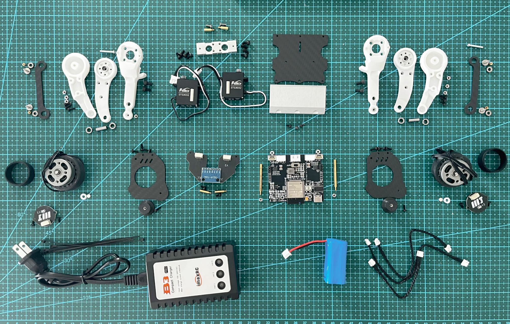
📦 Resources
- Bill of Materials (PDF) — Download here
- Core & Firmware (GitHub) — Open repo
🖨 Print settings
Recommended materials per part group:
- Frame, leg arms, motor mounts — engineering-grade filament (PC, PC-CF, PA-CF, ASA, or ABS+). These parts take real load.
- Wheel hubs & connectors — PETG or ABS works.
- Tires / feet — TPU.
- Jigs and non-load parts — PLA is fine.
🛠 Tools you'll need
| Item | AliExpress | Amazon | Notes |
|---|---|---|---|
| Soldering Iron TS101 | AliExpress Link | Amazon Link | (Recommended) |
| Heat Inset Tip Kit - For TS101 | AliExpress Link | Amazon Link | (Recommended) |
| Electric Precision Screwdriver | AliExpress Link | Amazon Link | (Recommended) |
| Allen Key Set | AliExpress Link | Amazon Link | (Recommended) |
| Torx Key Set | AliExpress Link | Amazon Link | (Recommended) |
| Torque Screwdriver | AliExpress Link | Amazon Link | (Recommended) |
| Wire stripper | Amazon Link | (Recommended) | |
| Wire cutter | AliExpress Link | Amazon Link | (Recommended) |
| Heat Insert Press Tool | AliExpress Link | Amazon Link | (Recommended) |
| Crimp Tool | AliExpress Link | Amazon Link | (Recommended) |
| Soldering Iron - Generic (Alternative) | AliExpress Link | Amazon Link | Budget friendly alternative |
| Heat insert tip - set (Alternative) | AliExpress Link | Amazon Link | Budget friendly alternative |
| Precision Screwdriver Set | AliExpress Link | Amazon Link | Budget friendly alternative |
Heat inserts and soldering pads on the controller PCB are M2 and M3 — see the if you haven't pressed inserts before.
🔧 Assembly
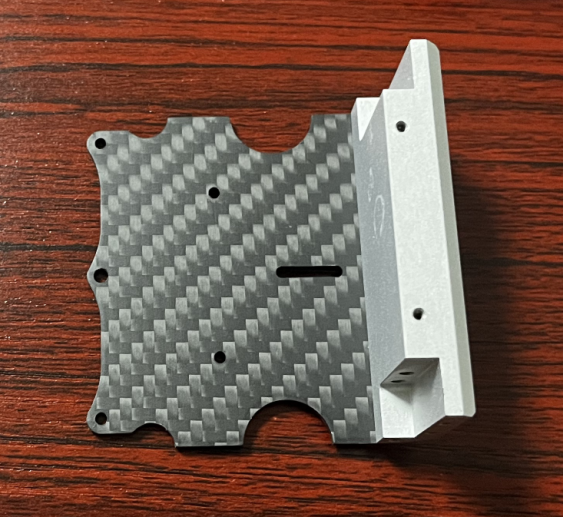
Baseplate & counterweight
Secure the baseplate and counterweight block with M3×8 screws.
Servo mounting
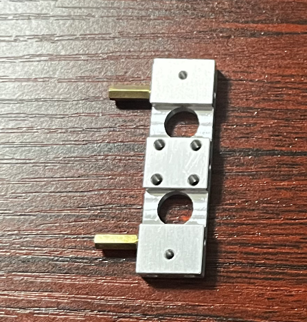
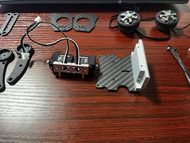
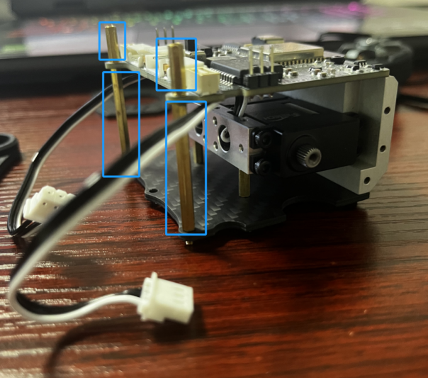
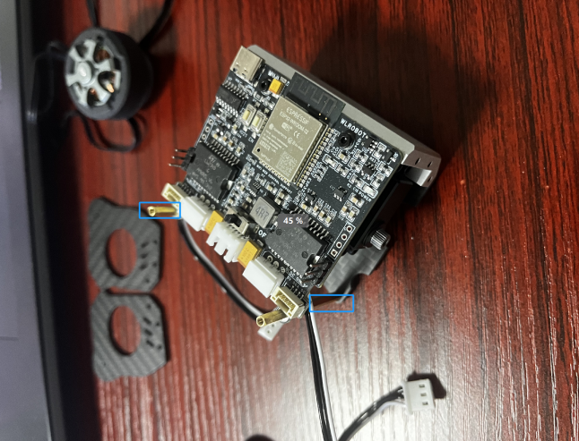
- Attach short brass spacers to the servo connection module.
- Mount the two STS3032 servos onto the module with the output shafts facing outward.
- Secure to the baseplate with M2.5×10 screws.

Mainboard installation
- Use long brass spacers at the front and short spacers at the rear to mount the ESP32 controller PCB.
- Press the M3 nuts into the 3D-printed leg connector slots before screwing in.
- Secure the side panels with M3×6 screws.
Wheel hubs
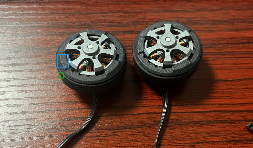
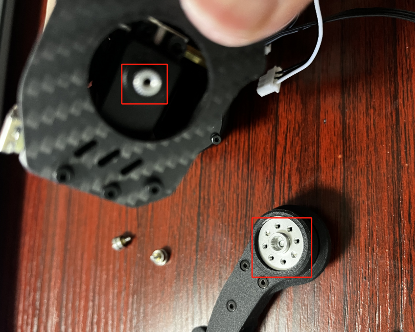
- Press the 3D-printed hub onto each gimbal motor and secure with M4×8 grub screws.
- Align the shaft flat to within ±0.2 mm — a sloppy flat will cause slip under jump load.
- Slide the TPU tire onto the hub.
Encoder boards
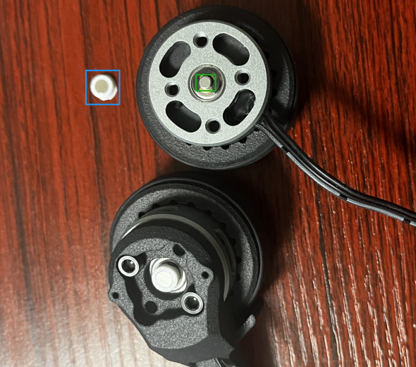
- Glue the 4×1 mm magnet to the white connecting post.
- Press the post onto the green-marked position on the motor shaft. A drop of CA helps.
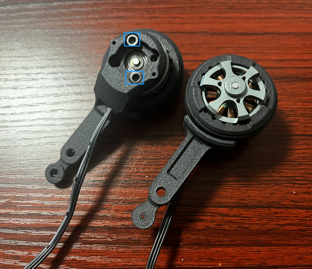
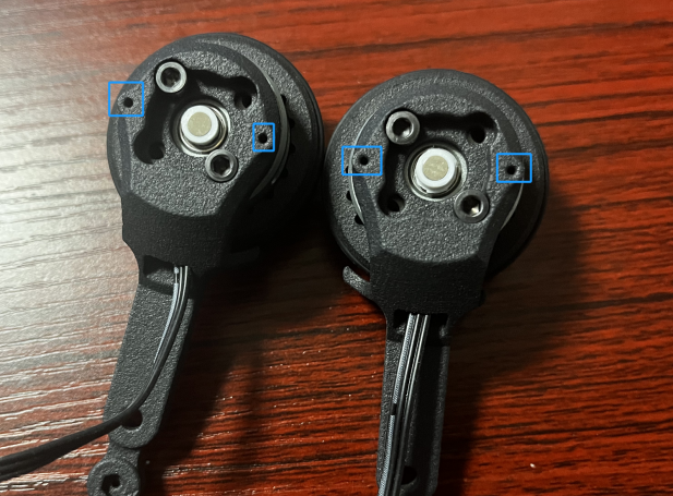
- The screw holes on the nylon-sintered leg parts are slightly tight — open them up before mounting the encoder PCBs.
Leg-motor connection
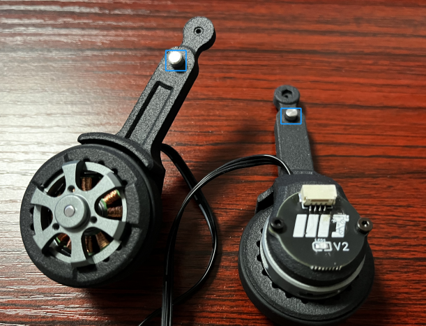
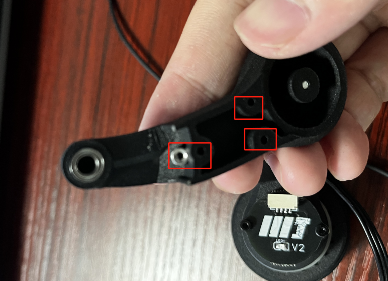
- Insert the connecting column into the leg part and slide the bearing onto the column.
- Press M2 nuts into their slots.
- Mount the servo arm into the leg, then connect the leg assembly per the diagram.
- Longer tire fenders go backward for obstacle clearance.
- Attach the legs to the brushless motors. Slide sleeves onto screws, mount bearings onto the sleeves, and fix them to the support structure.
💻 Firmware & calibration
Source, libraries, and the FD calibration tool live in the repo: - Core & Firmware (GitHub) — Open repo
Servo zero-position calibration
You'll need:
- Arduino IDE 2.3.4
- ESP32 board package v2.0.3 (newer versions break the servo lib — pin to 2.0.3)
- FD calibration tool (`/Tools/FD1984-240227/FD.exe`)
Steps:
- Open `SteeringEngineDebug.ino` from `/Tools/SteeringEngineDebug` and upload it.
- Power on the bot before plugging USB into the computer — order matters.
- Select ESP32 Dev Module and upload.
- Place the bot on its support block and disconnect one servo cable so the two STS3032s don't conflict on the bus.
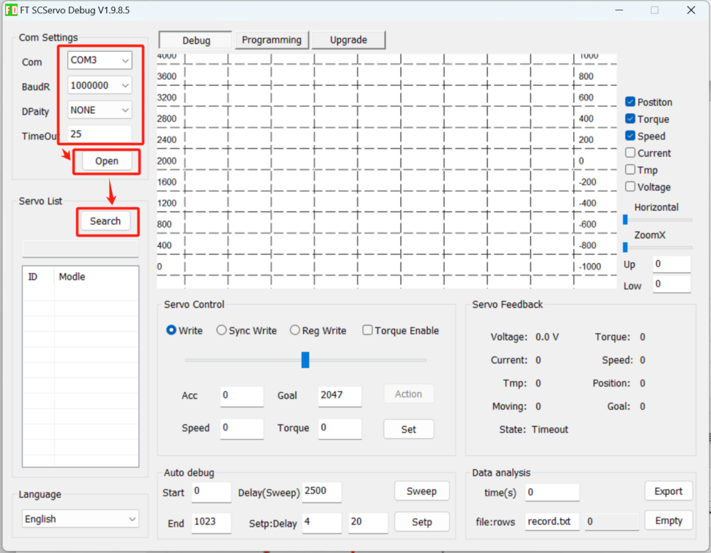
- In FD: select the COM port, set the baud, connect, and search. The detected `STS3032` is the left leg servo. Reconnect the right servo, set its ID to 2, and repeat zero-position calibration.
- Reconnect both servo cables.
Flashing the main firmware
- Open `/Src/wl_pro_robot` in Arduino IDE.
- Install the bundled libraries from `/Src/libraries` one by one.
- Set partition scheme to No OTA (Large APP) — the binary is too big for the default scheme.
- Select ESP32 Dev Module and upload.
🎮 First run
- Plug a 7.4 V 1100–1500 mAh LiPo into the XT30.
- Flip the switch. Red LED + a few seconds of self-test.
- Connect your phone to WiFi `navbot_en01-XXXXXX`, password `12345678`.
- Open `http://192.168.1.11` in your browser.
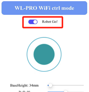
- Tap Robot Go and lift the bot off the ground — it should self-balance within ~2 seconds. Set it down and drive.
📜 Credits & license
This build is derived from the open-source Navbot-EN01 project by fuwei007 on GitHub. The firmware and calibration tooling come directly from that repo; the chassis, PCBs, and documentation in this listing are my adaptation.
If you build one, post a make — I read every comment and I'll fix the things you flag in the next revision.
💛 Support
If this project saved you a weekend of part-sourcing, ordering anything from the BOM PDF through the affiliate links costs you nothing extra and helps fund the next build. Thanks.

Gostou deste modelo? Crie uma conta grátis para salvar seus favoritos e voltar a eles depois.
Criar conta