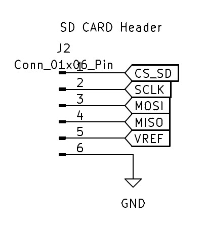
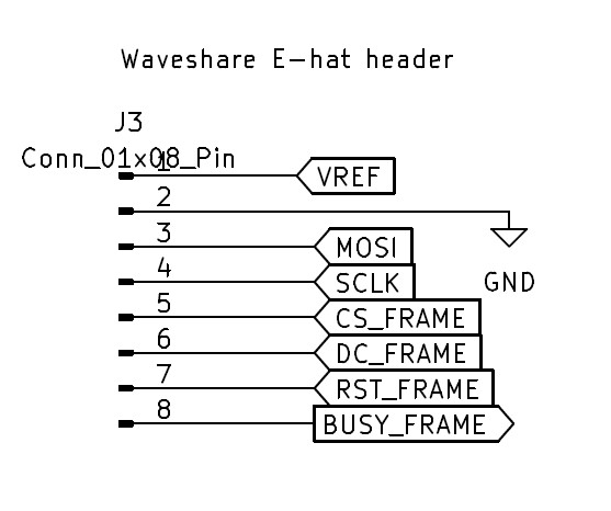
We need a package of straight DuPont-style male row connectors in order to make the 1x2, 1x6, and 1x8 Connectors. Also (10Cm) short multicolor Dupont Female to Female wires.
Note that the Micro SD Card doesn't need much capacity. A 1Gb Micro SD Card should work.
I used Python 3.9 with the Pillow (Python Image Library) 9.3.0 package installed. The latest of each should work.
Optional Software
Package
Version Used
Freecad
0.21.2
KiCad
7.0
Printing Instructions
Printer Settings
Settings
Used
Notes
Material
PLA
Nozzle
0.4mm
Layer Height
0.2mm
Walls
5
Needed for Brass Inserts
Infill
20%
Supports
Only Touching Build plate
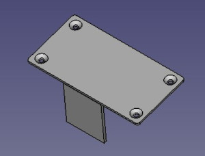
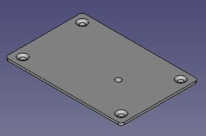
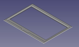
3D Printed Parts List
Part
Picture
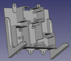
Main Part
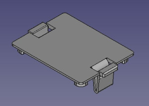
Battery Cover
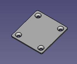
SD Card Cover
Display HAT Cover
Main Board Cover
Frame Border
PCB Board Instructions
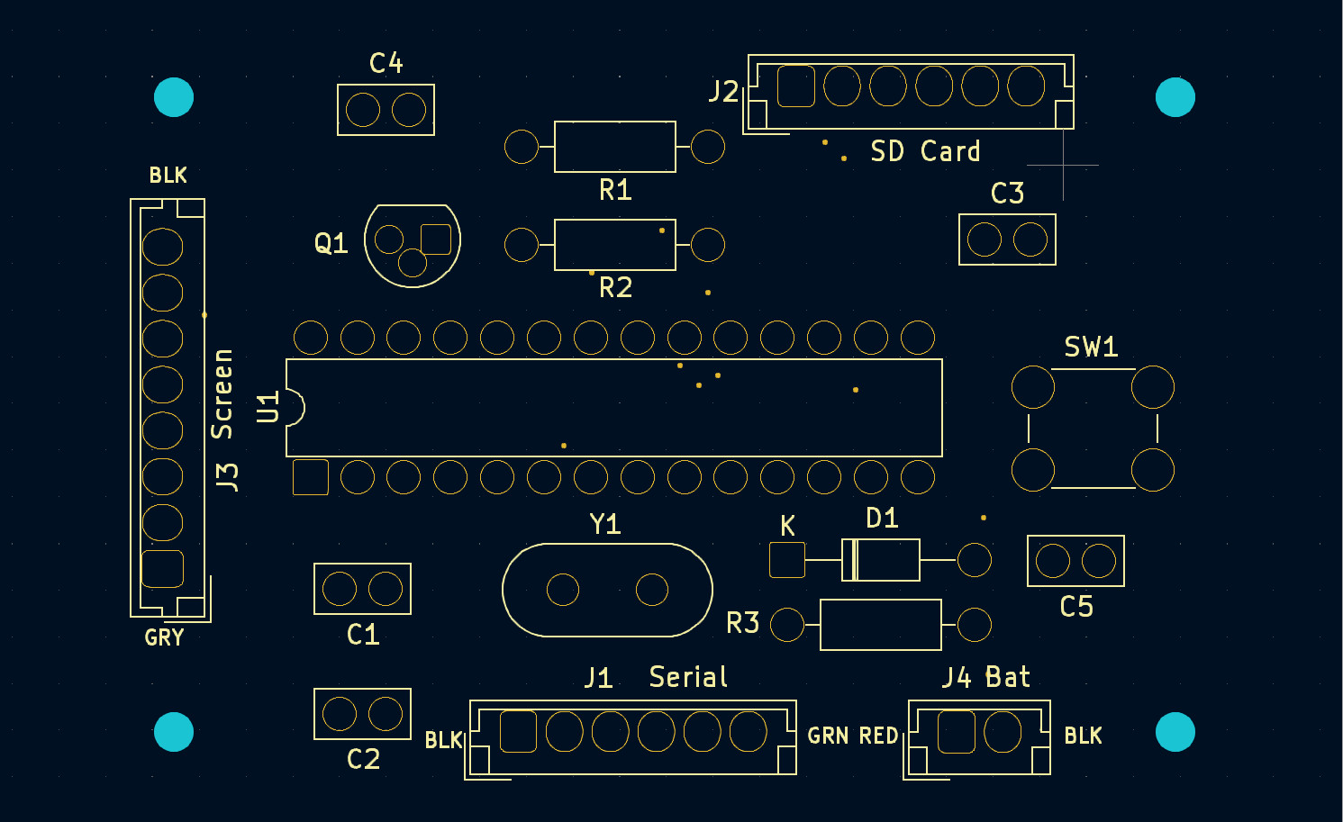
Gerber files are listed in the gerber directory. I used OshPark to create the PCBs, but you should be able to use other vendors.
Assembly Instructions
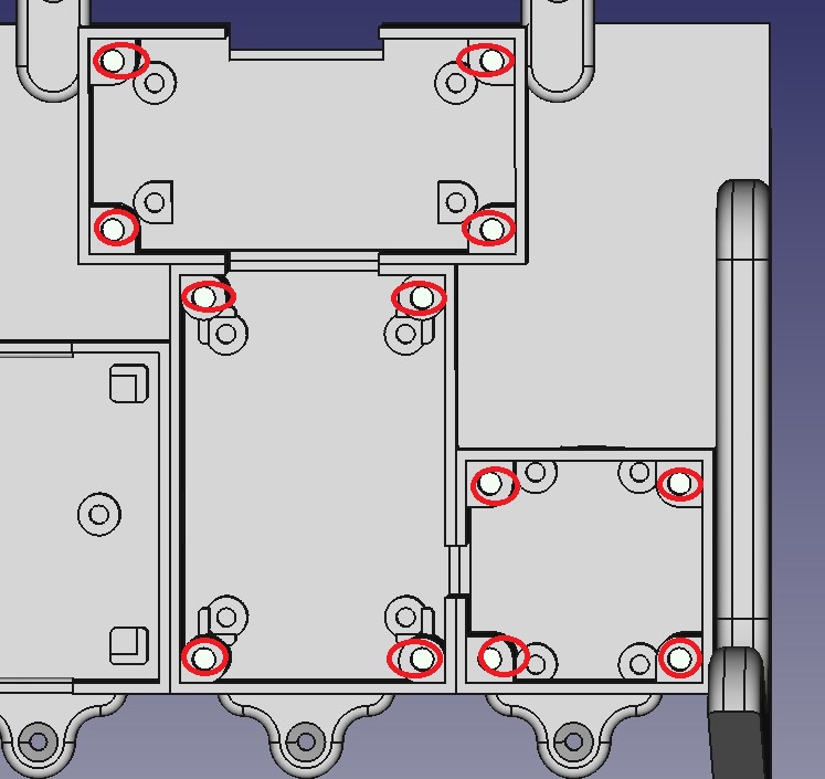
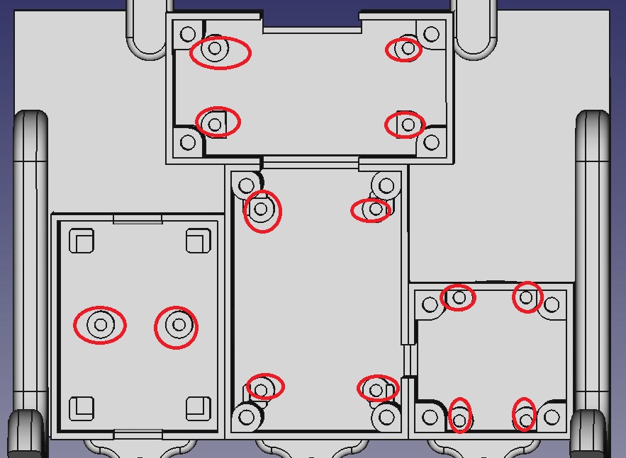
Insert the M2.5 Brass Inserts into the Following Holes
Use a solder gun to insert the brass inserts.
Insert the M2 Brass Inserts into the Following Holes
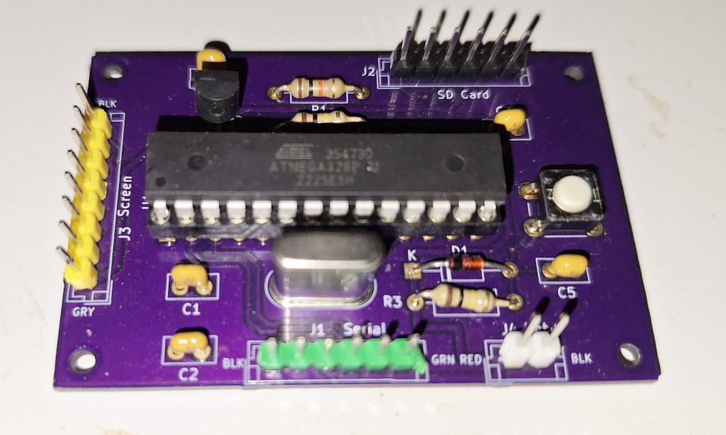
Solder Components to PCB Board
Solder components to the PCB board. The silkscreen shows the Component number location.
Component Number
Part
C1, C2
22pF
C3, C4, C5
100nF
D1
General Purpose Diode
J1, J2
Male Connector 01x06 Pin
J3
Male Connector 01x08 Pin
J4
Male Connector 01x02 Pin
Q1
PMOS - LP0701N3-G
R1
10K Resistor
R2, R3
100K Resistor
SW1
Push button switch
U1
28 Pin Connector for ATmega328-P
Y1
16Mhz Crystal
Assemble the Main Part to Frame
Remove the original back assembly from the picture frame. We do not need the back of the picture frame, the screws, or the stand. We only need the picture frame and the glass.
Mark Drill Holes. (See frame back picture)
Drill holes into the picture frame using a 5/64 or 2mm drill bit.
Remove any stickers from the glass. Clean glass the glass using glass cleaner or isopropyl alcohol. Ensure that no fingerprints are on the inside glass.
Assemble in the following order:
Wooden Frame
Glass
3D Printed Frame border
E-paper display (Be sure the protective covering is removed and the e-paper display ribbon cable is at the top.)
3D Printed Main Body
Use the #4 wood screw holes to attach the 3D Printed main body to the wooden picture frame.
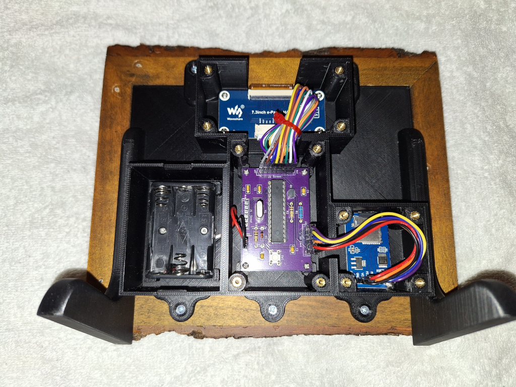
Put Boards into Main Picture Frame
Connect the Ribbon Cable to the E-Hat
The extension cable for the e-paper display is not needed. Connect the ribbon cable from the display to the e-hat. Use M2 roundhead screws to attach the e-hat.
Attach the Battery Case
Push battery wires through the holes in the main body. Attach the battery case using M2 Flathead screws.
Attach the Other Components to the Main Board
SD Card Adapter and Main Board used M2 Roundhead screws. Be sure that the hole in the main body for the SD Card matches the SD Card slot.
Attach the main PCB board. Ensure that the J3 screen is next to the hat connector and the SW1 is at the bottom of the display.
Make Connections to PCB Board
Attach the battery to J4. PCB board is marked red for positive and black for negative.
Attach SD card connections to J2. Chip select is closest to R1. Please double-check schematic.
Attach the Waveshare e-hat SPI connections to J3. Gray should match GRY on the board. Note that the BLK wire may be purple.
Arduino Code
Arduino Code Overview
I had to make a couple of changes to the Waveshare drivers. They are:
A. Changes with Waveshare drivers (SPI frequency and chips select)
B. Reduced the SPI clock speed.
Download Instructions
Use Board type "Arduino Uno"
Attach FTDI USB to serial connector to J1 serial connector.
Enable Serial Debug
If you run into problems, you may want to enable serial debugging. To enable serial debug out, uncomment line 50.
// Include this flag to turn on serial logging.
// #define SERIAL_DEBUG
The last failure is saved in the EEPROM. When booting, the error code is outputted over the serial port. The error codes are listed in line 36 of debug.h.
The Micro SD Card capacity can be small since the images don't occupy much space. Format a Micro SD Card using Fat32. Copy the processed image files to the root of the Micro SD Card.
Insert the Micro SD Card into the Micro SDCard Adapter for Arduino.
Testing and Putting it Together
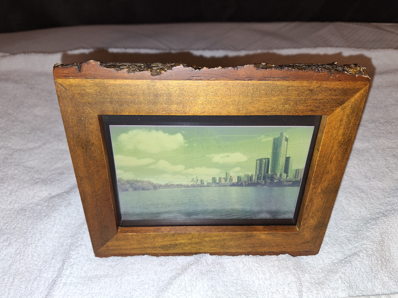
Verify that the image appears on the e-paper display.
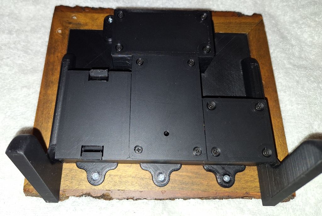
Attach the 3D-printed covers.
Battery Life and Power Consumption
It takes about 134 seconds to change the image on the screen. During this time, it uses approximately 30mA.