Você está no 3DFinder
Buscamos em Thingiverse, MakerWorld e Printables ao mesmo tempo para te dar o melhor de cada uma.
Descrição
This is a redesign of markus_p's Mini FPV-Rover, modified to be controlled by a Raspberry Pi Zero W with camera, using the control software created by Wingman94 for it's ZeroBot Pro.
Some changes from the original rover:
- Direct WiFi connection with the Raspberry Pi Zero W.
- Controlled via a web browser.
- Added a headlight.
- Redesigned the hull, making it easier to print and use less filament.
- Redesigned the wheels, removing the need of supports.
- Changed the track rubber shape to increase the grip.
- Made it use smaller magnets, making more room for the electronics.
- Added a charging port and on/off button with LED indicators.
- Everything redesigned with FreeCAD 0.17, full source code provided.
---------
Este é um redesenho do Mini FPV-Rover criado por markus_p, modificado para ser controlado por um Raspberry Pi Zero W com câmera, utilizando o software de controle criado por Wingman94 para o seu ZeroBot Pro.
Algumas alterações em relação ao rover original:
Conexão WiFi direta com o Raspberry Pi W
- Controle via navegador web.
- Adição de faróis.
- Redesenho do casco, facilitando a impressão e minimizando o uso de suporte.
- Redesenho das rodas, removendo a necessidade de suportes.
- Alterada a forma da borracha do elo da esteira, melhorando o atrito.
- Utilizados ímãs menores, aumentando o espaço interno para os eletrônicos.
- Adicionada porta para carga da bateria e botão liga/desliga com LEDs indicadores.
- Tudo redesenhado no FreeCAD 0.17, com o código completo disponível para download.
Instruções sobre impressão e montagem em português após as instruções em inglês.
Extra Hardware / Materiais Adicionais
Extra hardware needed:
| Qty. | Description |
|---|---|
| 1 | Raspberry Pi Zero WH |
| 1 | Raspberry camera module |
| 1 | TP4056 lithium battery charger Will change to this one: 5V Power Module LiPo Charger |
| 1 | ICR18650 lithium ion battery 2600mAh |
| 1 | Dual channel DC motor driver |
| 8 | Bearings 8x12x3.5mm |
| 2 | Motors (with 300 rpm) |
| 8 | Screws M3 x 14mm |
| 16 | Magnets 2mm x 1mm (disc) |
| 1 | Kcd11-101 Switch |
| N | Jumper wire |
| 1 | LED - 3mm bi-color common anode Will change to this one: LED - 3mm color common cathode |
| 1 | LED - 5mm any color |
| 2 | Cheap LED flashlights, to source LEDs and glasses for the headlight. (optional) |
| It can be used any small(not higher than 5.5mm) LED here, just change the resistors accordingly. The headlight glass can also be made cutting two 12mm discs from any transparent/translucent plastic sheet. | |
| 2 | 22Ω Resistors (Adjust according with the headlight LEDs) |
| 2 | 1.5K Resistors |
| 1 | BC337 Transistor |
| 2 | Zip Ties - 2.5x100mm |
| 2 | JST connectors - AWG20 Male (optional) |
| 2 | Pairs of male/female connectors (optional) |
---------
Materiais adicionais necessários:
| Qtd. | Descrição |
|---|---|
| 1 | Raspberry Pi Zero WH |
| 1 | Câmera para Raspberry Pi |
| 1 | Carregador de bateria de lítio TP4056 Será substituido por este: Carregador de bateria de lítio com saída de 5V |
| 1 | Bateria de lítio de 2600mAh ICR18650 |
| 1 | Controlador para motor DC de canal duplo |
| 8 | Rolamentos de 8x12x3,5mm |
| 2 | Motores (com 300 rpm) |
| 8 | Parafusos M3 x 14mm |
| 16 | Ímãs de 2mm x 1mm (disco) |
| 1 | Chave Kcd11-101 |
| N | Cabo jumper |
| 1 | LED - 3mm bicolor ânodo comum Será substituído por este: LED - 3mm bicolor catodo comum |
| 1 | LED - 5mm qualquer cor |
| 2 | Lanternas LED baratas, para utilizar os LEDs e o vidro na montagem do farol. (opcional) |
| Aqui pode ser utilizado qualquer LED pequeno(não mais alto que 5,5mm) bastando trocar os resistores de acordo. O vidro do farol também pode ser feito cortando dois discos de 12mm de qualquer folha de plástico transparente/translúcido. | |
| 2 | Resistores de 22Ω (Ajustar de acordo com os LEDs do farol) |
| 2 | Resistores de 1.5K |
| 1 | Transistor BC337 |
| 2 | Abraçadeiras de nylon - 2.5x100mm |
| 2 | Conectores JST - AWG20 Macho (opcional) |
| 2 | Pares de conectores macho/femea (opcional) |
Alguns destes itens podem ser encontrados também em outros sites como o mercadolivre.com.br, as lanternas podem ser encontradas também em lojas de bugiganga.
Printing
Print the parts in the quantities indicated:

Parts marked in green must be printed with flexible filament.
General Print Settings
Layer height: 0.15mm
Infill: 20%
Detailed Print Settings
Hull
Slic3r print settings:
- Detect bridging perimeters: checked
- Detect thin walls: checked
- Generate support material: checked
- Overhang threshold: 4º (this reduces the support to the exact minimum required)
External perimeters: 0.3mm
Track Link
Slic3r print settings:
- Detect bridging perimeters: checked
- Detect thin walls: checked
- External perimeters first: checked
- External perimeters: 0.3mm
Track Link Rubber
Should be printed with flexible filament.
Slic3r print settings:
- Avoid crossing perimeters: checked
- Detect thin walls: checked
Headlight Support
Must be printed with flexible filament.
Slic3r print settings:
- Detect bridging perimeters: checked
- Avoid crossing perimeters: checked
- Detect thin walls: checked
Assembling
Electronics
Wiring Diagram
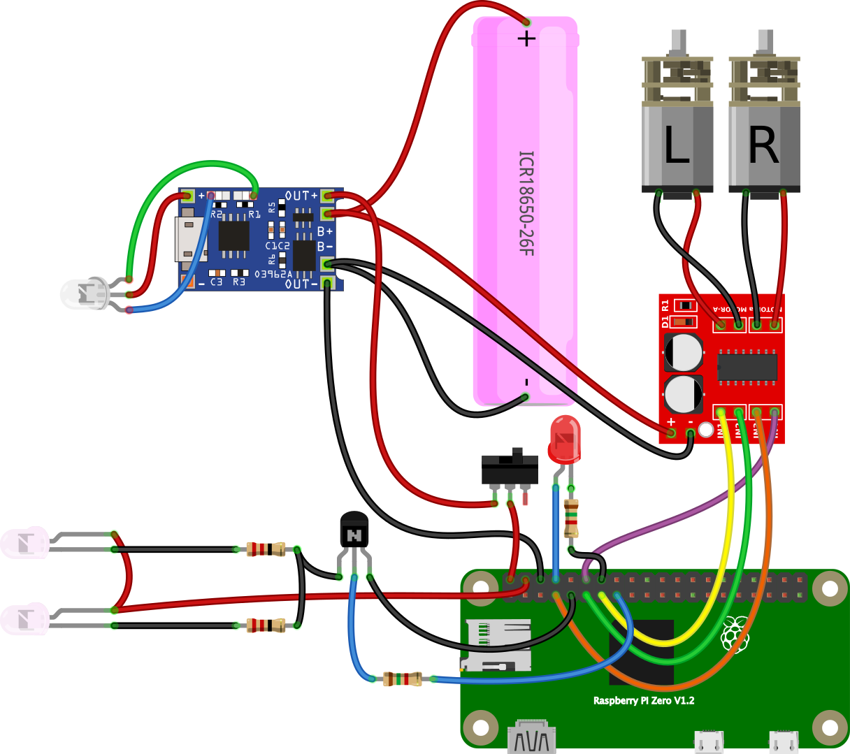
Note that the battery charge indicator LED has terminals directly soldered to SMD LED pads on the battery charger board. (board LEDs can be removed if needed)
Hull
General Assembly
The following animation shows how most of the pieces fit together.
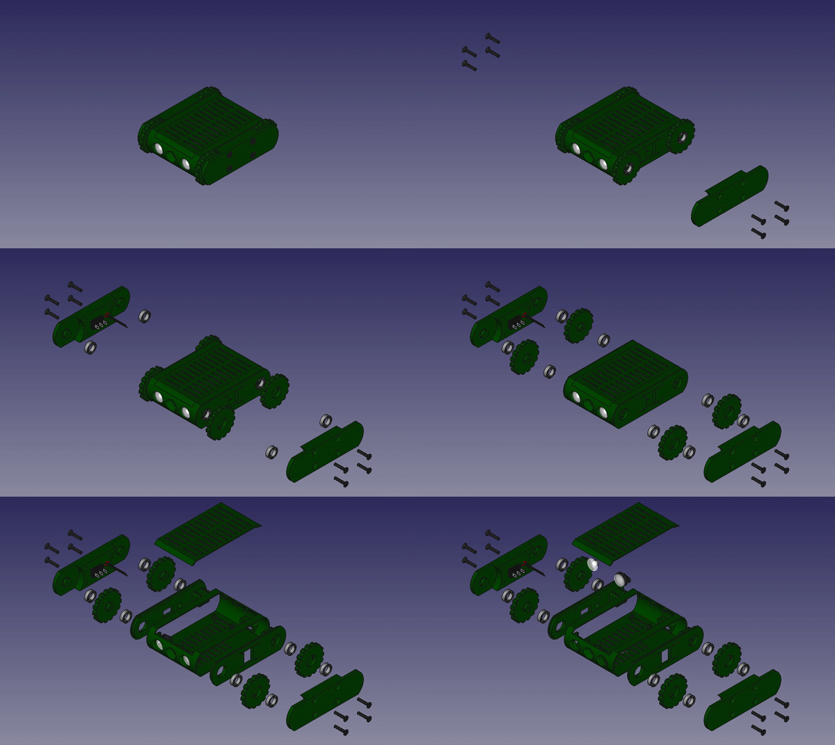
Assembly Details


The images above detail the headlight assembly.

Solder the bicolor LED and all cables on the top side of the charging board. (old board)

Solder the bicolor LED and all cables on the top side of the charging board. (new board)

Use double-sided tape to attach the charging board to the hull.

 Solder all cables on the motor controller board then protect it with heat shrink tube(16mm) or electrical tape.

Assemble the left chassis and insert the motor and zip ties.

Position the camera flat cable, bending it according to the image.

Place the battery and route the cables through the zip ties.

Before locking the zip ties, check if the position of the flat cable relative to the battery conforms with the image above.
Lock the zip ties.

Assemble the right chassis and insert motor, LED and the power switch.
The parts must be mounted on the hull in this order:
- Headlights.
- Battery charger board.
- Left chassis (already dock the camera)
- Raspberry Pi (connect the camera cable and insert the sdcard before attaching it to the hull)
- Right chassis
- Motor control board
- Tracks and cover
Test the entire system before gluing the hull to the chassis.
Software
Download the sdcard image (MiniRoverZero.zip) unpack it and write the img file to the sdcard using something like Etcher.
To drive the rover, turn it on (first boot takes some time), connect to the "minirover" WiFi using "minirover" as the password, then open one of this addresses:
[http://minirover.zero/](http://minirover.zero/)
or
[http://10.0.0.1/](http://10.0.0.1/)
It's also possible to ssh into it using the default raspberry pi user and password, to change anything if needed.
Imprimindo
Imprima as peças nas quantidades indicadas:
As peças marcadas em verde devem ser impressas com filamento flexível.
Configurações Gerais de Impressão
Altura da Camada: 0.15mm
Preenchimento: 20%
Configurações Detalhadas de Impressão
Casco (Hull.stl)
Configurações do Slic3r:
- Detect bridging perimeters: marcado
- Detect thin walls: marcado
- Generate support material: marcado
- Overhang threshold: 4º (isto reduz a quantidade de suporte para o mínimo necessário)
- External perimeters: 0.3mm
Elo da Esteira (TrackLink.stl)
Configurações do Slic3r:
Detect bridging perimeters: marcado
- Detect thin walls: marcado
- External perimeters first: marcado
- External perimeters: 0.3mm
Borracha do Elo da Esteira (TrackLinkRubber.stl)
Deve ser impressa em filamento flexível.
Configurações do Slic3r:
- Avoid crossing perimeters: marcado
- Detect thin walls: marcado
Suporte do Farol (HeadlightSupport.stl)
Precisa ser impresso em filamento flexível.
Configurações do Slic3r:
- Detect bridging perimeters: marcado
- Avoid crossing perimeters: marcado
- Detect thin walls: marcado
Montando
Eletrônica
Esquema de Ligações

Mecânica
Montagem Geral
Esta animação mostra como a maioria das peças se encaixam:
Detalhes da Montagem
As imagens acima detalham a montagem dos faróis.
Soldar o LED bicolor e todos os cabos no lado de cima da placa carregadora de bateria.
Soldar o LED bicolor e todos os cabos no lado de cima da placa carregadora de bateria. (placa nova)
Utilizar fita dupla face para fixar a placa carregadora de bateria no casco.
Soldar todos os cabos na placa controladora de motor e proteger com espaguete termo retrátil(16mm) ou fita isolante.
Montar o chassis esquerdo inserindo o motor e abraçadeiras de nylon.
Posicionar o cabo da câmera realizando uma dobra suave conforme a imagem.
Posicionar a bateria passando os cabos por dentro das abraçadeiras.
Antes de travar as abraçadeiras verificar a posição do cabo da câmera em relação a bateria para que fique conforme a imagem.
Travar as abraçadeiras.
Montar o chassi direito inserindo motor, LED e a chave liga/desliga.
As peças devem ser montadas no casco nesta ordem:
- Faróis.
- Placa carregadora de bateria.
- Chassi esquerdo (já encaixar a câmera)
- Raspberry Pi (conectar o cabo da câmera e inserir o cartão SD antes de encaixá-lo no casco)
- Chassi direito
- Placa de controle dos motores
- Esteiras e tampa
Testar todo o sistema antes de colar definitivamente o casco aos chassis.
Software
Baixe a imagem do sistema (MiniRoverZero.zip) descompacte e grave no cartão SD usando o Etcher ou o dd.
Para comandar o rover, uma vez ligado (o primeiro boot demora um pouco), conecte à rede WiFi "minirover" utilizando a senha "minirover" e então abra um destes endereços no navegador:
[http://minirover.zero/](http://minirover.zero/)
ou
[http://10.0.0.1/](http://10.0.0.1/)
Também é possível conectar ao sistema via ssh utilizando o usuário e senha padrão do raspberry pi, caso queira modificar alguma coisa.
Category: Robotics
Gostou deste modelo? Crie uma conta grátis para salvar seus favoritos e voltar a eles depois.
Criar conta