Você está no 3DFinder
Buscamos em Thingiverse, MakerWorld e Printables ao mesmo tempo para te dar o melhor de cada uma.
Descrição
Introduction
This solar viewer projects the image of the sun onto a screen so that it can be viewed safely. At other times you can use this viewer to study sunspot activity. There are a couple of other designs online, but this design has an adjustment for each lens that allows you to fine-tune the alignment. It's designed around a shelf rail because it's inexpensive, widely available, and fairly rigid. Having a square rail instead of a round rail also helps with alignment of the parts along the optical axis. There are parts compatible with M5 hardware and parts compatible with #10-32 hardware.
The instructions below have a list of printed parts to make, a list of other materials and tools with suggested sources. Especially, make sure you purchase the right lenses. There are detailed assembly and alignment instructions.
Good luck and happy viewing!
Credits
The video that Destin at Smarter Every Day did on the upcoming eclipse - it is what inspired me to travel for the eclipse and to build this viewer. This design is adapted from the work of TR Richardson at College of Charleston and uses the recommended lenses from his Large Two Lens SSV design. It also borrows the lens-aiming concept from the Hadley open source telescope, although this design uses lock nuts instead of springs. You can also use the viewer to observe sunspots.
Other Resources
- Another printable design - @Long's design based around a fiberglass pole
- Solar Eclipse Sharp and Fuzzy Shadow tool - printable version of the tool described in the Smarter Every Day video
Warnings and Safety

- When using the viewer outside, never look at the sun through the lenses. This can blind you. It is only safe to view the projected image by looking at the screen.
- The primary lens can focus enough sunlight to burn something. Don't place any part of your body or anything flammable into the optical path of the viewer.
- Pay attention to the alignment of the primary lens. If it gets misaligned, it can melt the mount of the Barlow lens or burn the shield material. You may want to cover the shield in aluminum foil.
- Use the end cap models provided to protect people from the sharp corners at the ends of the rail
- Do not look directly at the eclipse with your eyes unless you have glasses with the filters with the right certifications.
- Do not look at the eclipse with a telescope unless you have the right solar filters covering the primary collector.
- Find out more with Eclipse Safety Information from NASA
Post-eclipse Retrospective
I've included some photos below, followed by some discussion of using the viewer in practice.
Just after first contact

Getting more occluded…

Entering totality
That's not sunset – that's the horizon during totality!
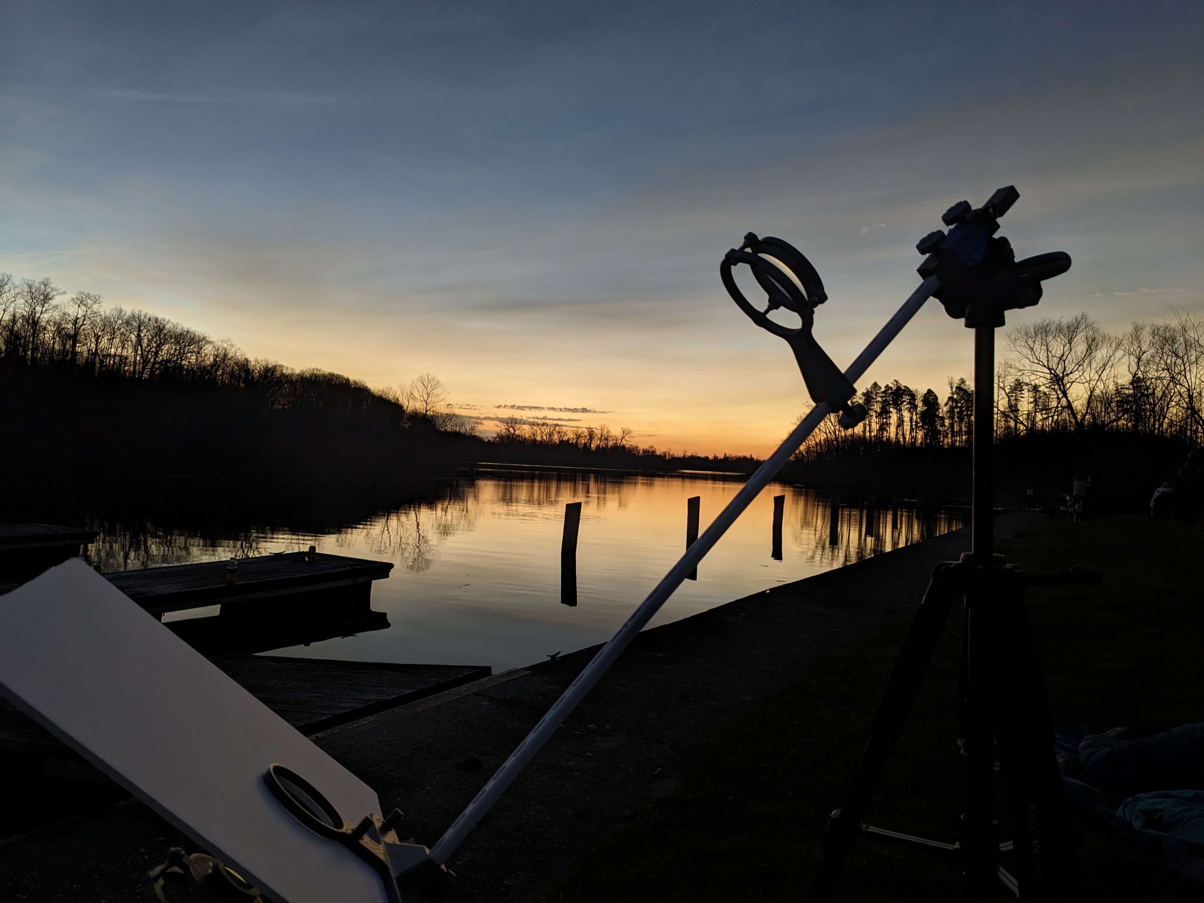
Just after third contact

The eclipse is waning

The Good
After using this for the eclipse, I can say with certainty that it was worth having, even if it was slightly difficult to use. Many kids and adults would come by to see it, and you could see a lot more detail than you could with the eclipse glasses. It also meant you could observe more of the environment around you (the cooling temperatures, the animal sounds, the horizon) while also keeping track of the eclipse.
One major change I made on the day was to put the tripod mount at the top end, above the primary lens. This made the whole thing more rigid since it was supported from both ends rather than having a fulcrum in the middle.
The sun moves fast – from one side of screen to the other is 2-3 minutes. So every few minutes, I would have to reposition it. Fortunately, it ends up being pretty easy to adjust. I've updated the alignment instructions below.
Although I could get a bigger image by putting the lenses farther apart, that image would move out of frame almost before I could get it centered. The image shown, about 5 inches in diameter, seemed to be a good compromise, and it was pretty bright.
Nothing showed on the viewer during totality (that I noticed), but I also wasn't looking very hard because the totality was amazing to see with your own eyes. Pictures don't do it justice. It is worth the trip to be in totality for an eclipse!
Things to improve
It's not clear that the lens aiming adjustments were much use because the viewer does not have a very rigid frame. The steel rail provides a reasonably straight rail, but it is very flexible, so trying to manipulate the bolts puts everything out of alignment. I think I would look at using a stiffer rail (maybe a double closet rail) in the future. Something like a broom handle would definitely be stiffer, but also harder to align.
I would make the screen bigger than what is shown.
If I could afford it or had time to build it, I would have an aiming mechanism that could track the sun automatically. If I had that, I would put a camera mount on it so I could film the whole thing. Maybe the camera could also be used as the control for the aiming mechanism with a simple bounding box algorithm that tries to keep the lighted area in the center.

Printed Parts
Printing parameters are given below:
- Parts should be printed in PETG with an 0.6mm nozzle. The Prusa Slicer defaults were used except:
- The tripod bracket should be printed with four perimeters and 50% infill.
- All other parts should be printed with four perimeters and 20% infill.
- For all parts, set layer height to “0.3mm Quality”, then use the adaptive layer height on every part with 0.5 quality/speed and radius 5 (the default settings). The adaptive layers can improve the quality of the holes and threaded parts.
- Each part is already oriented the “best” way for printing in the STEP and 3MF files.
- If you are adjusting the plates, pay attention to the orientation of parts with holes in vertical surfaces – the “point” on these holes should face up when the part is on the print bed.
- Supports are not required
- Gcode files are included for weight and time estimates, but you should slice your own prints.
The parts you need to print are assembled into the three plates as Prusa Slicer project files. These already have the recommended settings described above. Choose the M5 variant for M5 hardware or the NUM10 variant to use #10 hardware.
- ssv_v3_plate1.3mf
- ssv_v3_plate_2_M5.3mf OR ssv_v3_plate_2_NUM10.3mf
- ssv_v3_plate_3_M5.3mf OR ssv_v3_plate_3_NUM10.3mf
Or you can assemble your own prints from the list of parts below.
| Qty | Part Name |
|---|---|
| 1 | Barlow holder cap |
| 1 | Barlow holder (choose M5 or #10 based on your hardware) |
| 2 | end cap |
| 2 | lens holder bracket (choose M5 or #10 based on your hardware) |
| 1 | middle shield bracket |
| 1 | primary holder cap |
| 1 | primary holder (choose M5 or #10 based on your hardware) |
| 11 | printed thumbscrew |
| 1 | screen bracket |
| 1 | tripod bracket |
Bill of Materials
All Amazon links are affiliate links.
Note that the design includes parts designed for M5 hardware or for #10-32 hardware. Only one set is needed to complete the build.
- Cost: If you are ordering online, the M5 parts are cheaper to obtain from Amazon. The #10 variant is primarily provided because you can walk into a Home Depot and purchase them off the shelf.
- You can substitute #10-24 hardware, but the fine threads on #10-32 hardware will give more control in adjusting the lenses.
- Be sure you print the right part variants for the hardware you chose! The two sets are not interchangeable!
| Qty | Part Name | Suggested Sources |
| 1 | 71.9mm diameter by 700mm achromatic doublet lens (see suggested sources for link) | surplusshed.com - This print is specifically designed for this lens set |
| 1 | 32.3mm Barlow lens with a focal length of -19mm (see suggested sources) | |
| 1 | C-channel shelf mounting rail, nominally 17x11 mm, length 68" or longer | Home Depot - the design was built using the Home Depot rail, so that is the preferred one, though other stores may have a similar rail Note: you can use a 48" rail, but it will result in a smaller image. |
| 1 | Tripod | Amazon - inexpensive lightweight tripod with a weight hook and an adjustable head. This is the tripod pictured in the design, though any tripod with a ¼-20 mount should work. Note: a tripod designed to carry more weight would probably be easier to aim, but this model works well enough if one end of the rail is allowed to rest on the ground. |
| 1 | 1/4-20 nut (for tripod rail bracket) | This nut is required for either the M5 or #10 designs because it is what connects to the tripod screw. 100 pack of 1/4-20 nuts - Amazon 4 pack of 1/4-20 nuts - Home Depot |
| 1 | 1" 1/4-20 screw, any head type | optional - used for screw pulling the 1/4-20 nut into the bracket. You can press the nut in with pliers if you don't have this part, it is just harder to get it fully seated. |
| 1 | sheet of foam core posterboard | 10 pack of 11"x14" - Amazon - but you can buy smaller quantities more cheaply in person at a craft store, office supply store, or big box store |
| M5 Hardware - choose this or #10 hardware below, but not both | ||
| 6 | M5 nuts | M5 assortment set - Amazon - this has M5 screws, washers, and nuts |
| 6 | M5x30 button or cap head screws | |
| 6 | M5 nylon lock nuts | M5 lock nuts - Amazon |
| #10 Hardware - choose this or M5 hardware above, but not both | ||
| 6 | #10-32 nuts | 5 screws and 5 nuts - Home Depot - NOTE: two packs required |
| 6 | #10-32 x 1.5" screws | |
| 6 | #10-32 nylon lock nuts | 4 lock nuts - Home Depot - NOTE: two packs required |
The models pictured were printed with Overture PETG Space Grey - Amazon; color is not important for functionality
Other tools needed
- For the M5 variant: metric hex key set (at least an M3 hex key), OR
- For the #10 variant: a Phillips screwdriver
- Needle nose pliers
- A craft/Xacto knife (for cutting foamcore posterboard)
Assembly Instructions
Instructions referencing hardware list the Metric Part (UNF part in parenthesis). Also, please ignore the print quality in the images – I was dealing with a nozzle clog and waiting on some cleaning filament. They look terrible but are completely functional.
Note: Screw pulling technique
This idea comes straight out of the Prusa MK3/4 assembly. If you can't insert a nut into the hole it is supposed to go into, put a screw in from the other side, then thread the nut onto it and line the flats of the nut up with the hole. Then tighten the screw to pull the nut into place. Once the nut is in place, remove the screw.
If you need a shorter screw and don't have one, “shorten” a screw by putting several nuts all the way up to the head before using it as a pulling screw.
Step 1: Prepare the lens holder assemblies
These assemblies hold the primary and Barlow lenses in alignment and provide adjustments for final aiming, as well as a thumbscrew to set the position of the bracket on the mounting rail.
- Use the screw pulling technique to seat an M5 nut (#10-32 nut) in each of three holes on the lens bracket

- Insert a M5x30 screw (#10-32x1.5" screw) into one the holes in the Barlow holder. The screws should point the opposite way from the cavity that holds the lens.
- Thread an M5 nylon lock nut (#10-32 nylon lock nut) onto the screw and tighten it until the screw does not rotate. Then back the nut off slightly until the screw is free to rotate, but does not rattle.
- Making the screw free to turn will allow it to move the holder relative to the nut in the lens bracket. Adjusting the three screws provides the aiming adjustment for the lens.
- Repeat for the other two screws holes.

- Align the screws in the Barlow holder with the holes in the lens bracket.
- Be sure the nuts in the lens bracket are facing away from the Barlow holder. If you don't, the whole assembly might fall apart!
- Thread the three screws in the Barlow holder into the three nuts in lens bracket until the ends of the screws are approximately flush with the face of the nuts.

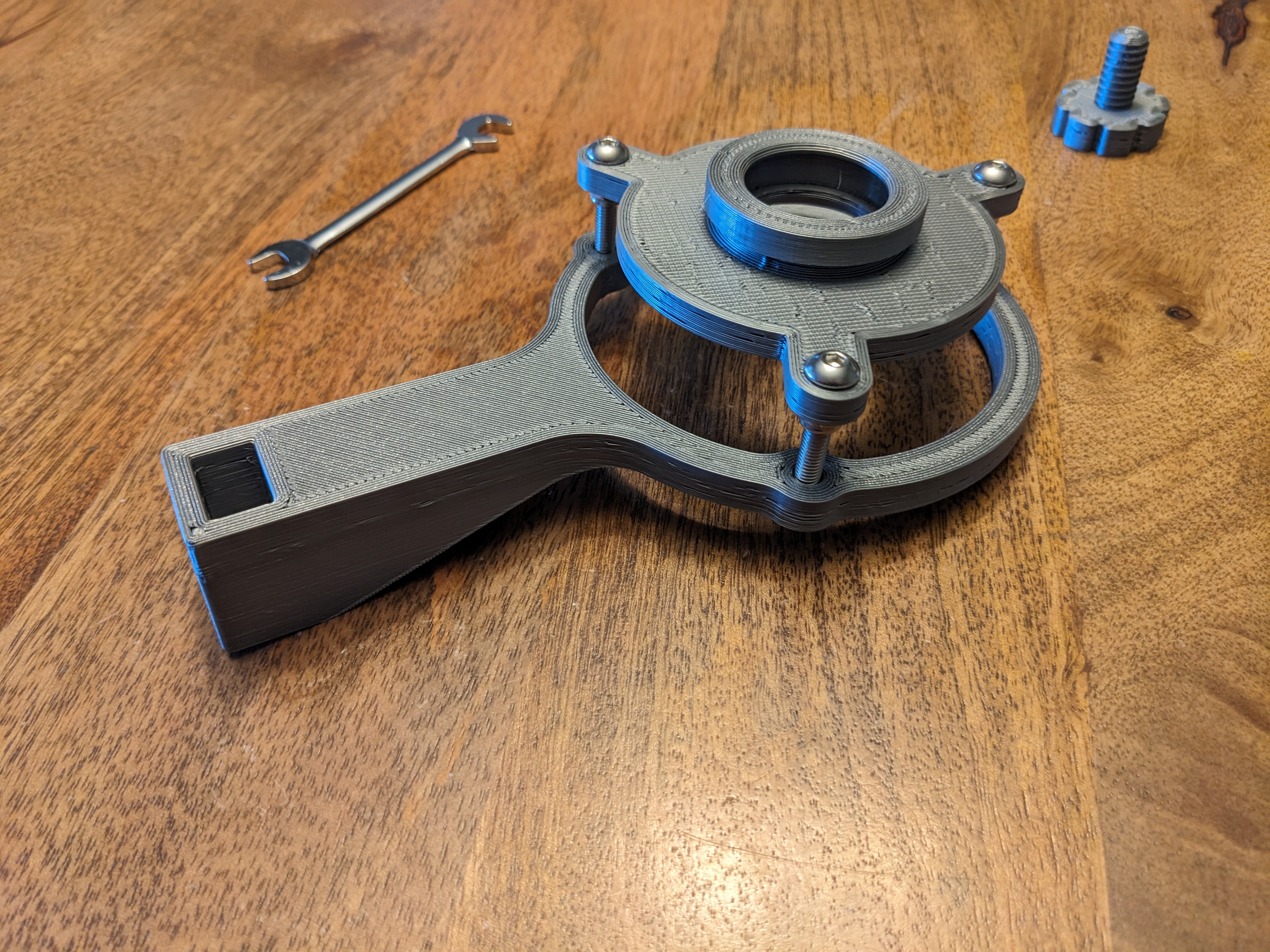
- Thread a printed thumbscrew into the hole in the bottom of the bracket. Do not screw it all the way in, there must be room for the rail to go into the channel first.

- Repeat these steps with the primary holder and the other lens bracket. The geometry of the three tabs on the primary lens holder and the Barlow lens holder are the same, only the size of the lens cavity is different.
Step 2: Install the lenses into the lens holders
- The primary lens is actually a pair of lenses
- biconvex lens - a lens that bulges out on both sides. Once side will be more curved than the other
- flint lens - a lens that is almost flat on one side and concave on the other.
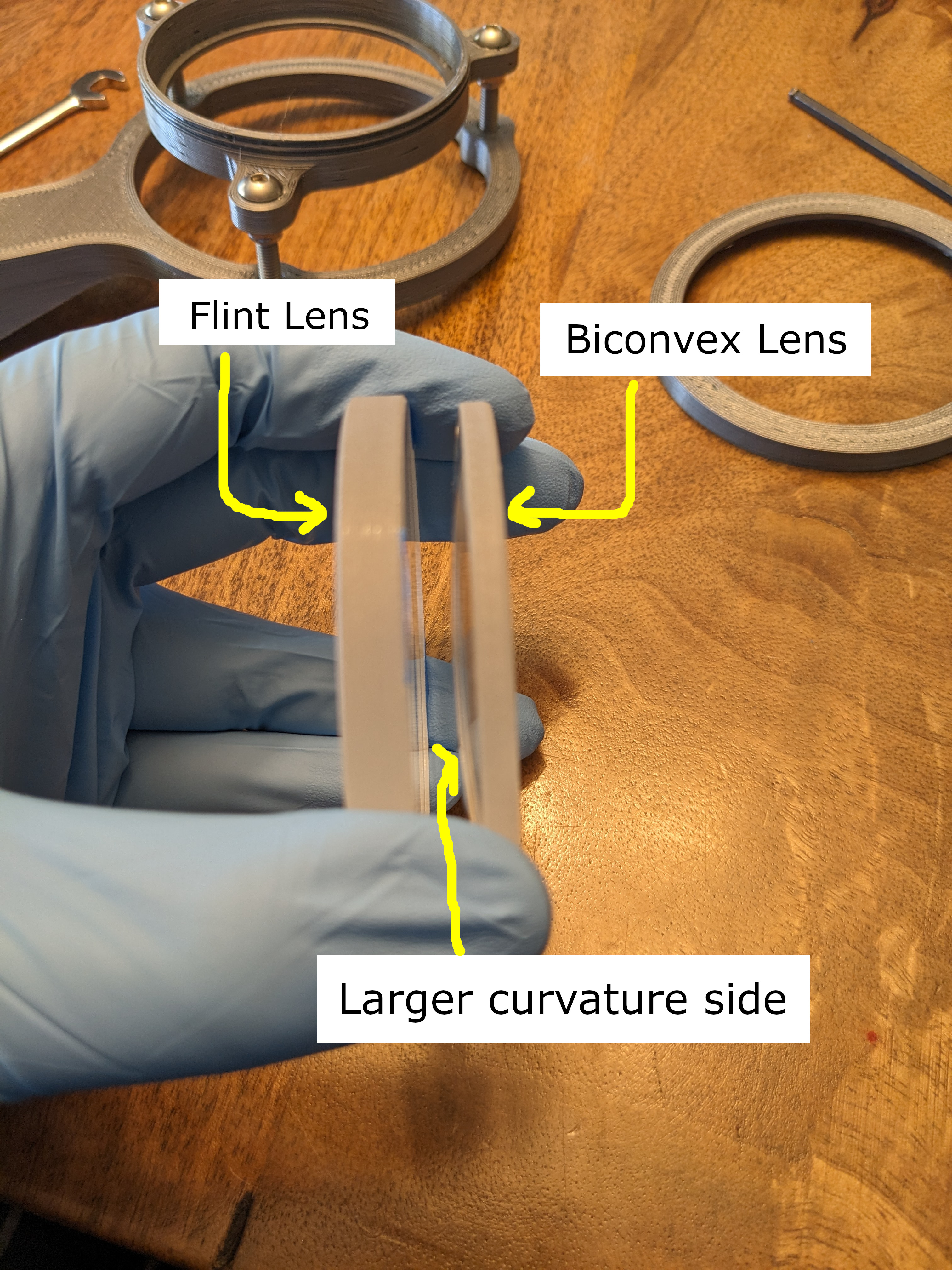
- Place a few small pieces of masking tape at the edge of the more curved side of the flint lens to act as a spacer.

- Place the more curved side of the biconvex lens against the curved side of the flint lens to make the primary lens pair.
- Place the primary lens assembly from step 1 flat on the table with the lens cavity pointing up.
- Place the primary lens pair inside the lens cavity of the primary lens holder so that the the biconvex lens is on top.
- This is the side the sun should shine through first.
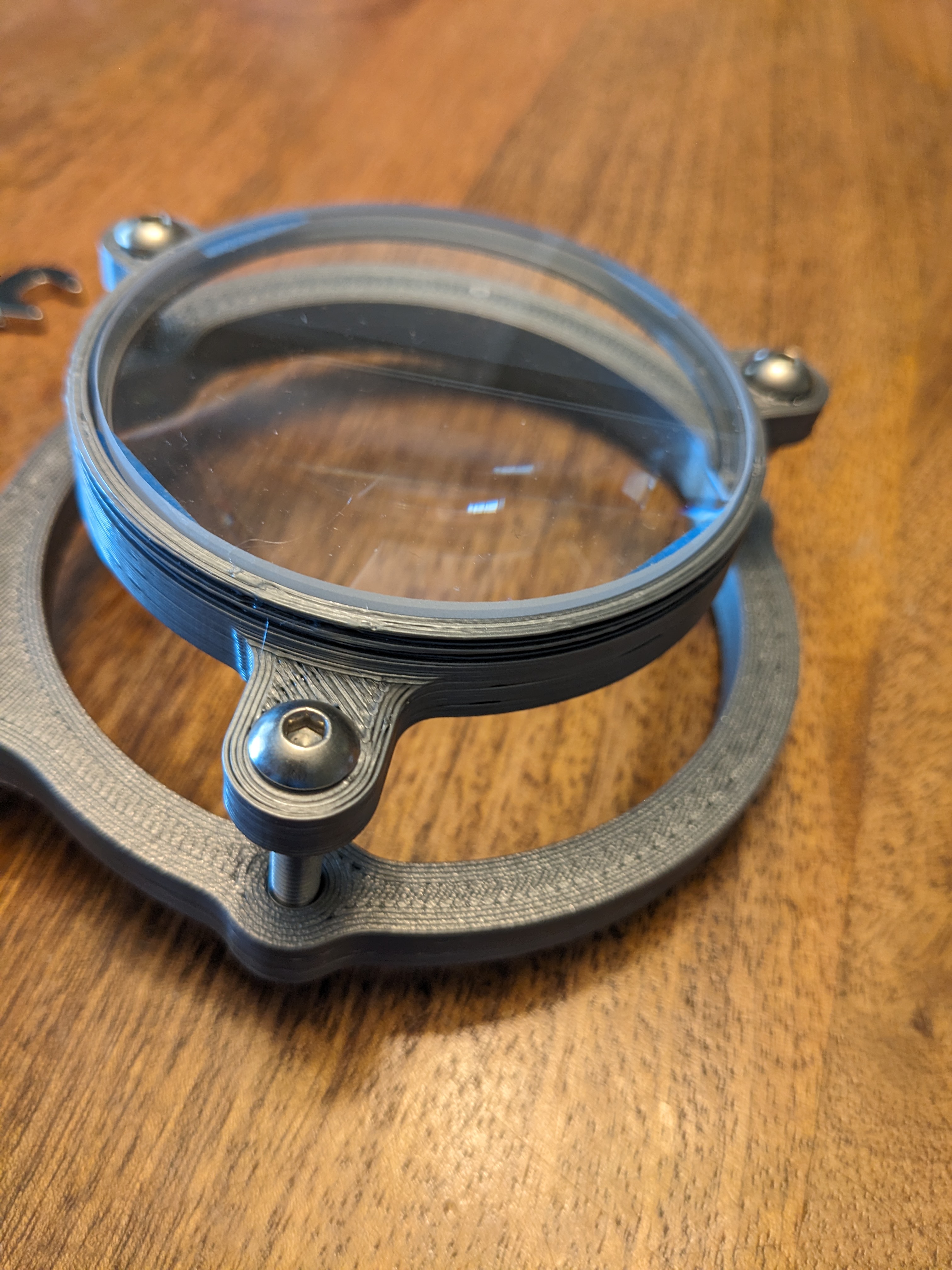
- Screw the primary holder cap onto the primary holder slowly until the you can't feel the lenses wiggle in the cavity.
- Do not over-tighten the primary holder cap, you might crack the lens!

- Repeat the sequence above with the Barlow lens, Barlow lens holder assembly, and the Barlow holder cap.
- Do not over-tighten the Barlow holder cap, you might crack the lens!
- The orientation of the Barlow lens in the lens cavity doesn't matter.


- Set the lens assemblies aside in a safe place so the lenses do not get damaged.
Step 3: Prepare the Screen Assembly
The screen assembly provides the surface that the image of the sun will be projected onto as well as a thumbscrew to set the position of the bracket on the mounting rail.
- Cut a piece of foamcore posterboard as large as is practical, but at least 10" x 10" (254x254mm) to make the screen.
- If you're using a regular posterboard size piece of foamcore, cut it in half and use half for this screen and half for the shield assembly below.
- Regular cardboard poster board or card stock will probably not be flat or rigid enough, so white foamcore posterboard is recommended for the screen.
- Align the bottom of the screen bracket with the middle of one edge of the screen.
- Trace the two threaded holes from the screen bracket onto the screen.

- Cut the holes you traced out of the screen. Make the cuts as close to perpendicular to the face as you can.

- Place the screen on the screen bracket with the best face turned away from the the screen bracket. Line up the holes in the screen bracket with the holes in the screen.
- Thread two printed thumbscrews through the foamcore and into the screen bracket until the heads hold the screen securely.
- If the holes in the screen are slightly too small, you can twist the thumbscrew into them and it will cut its own threads in the foamcore.
- Do not over-tighten the printed thumbscrews. This could bend the screen or crack the screws themselves!
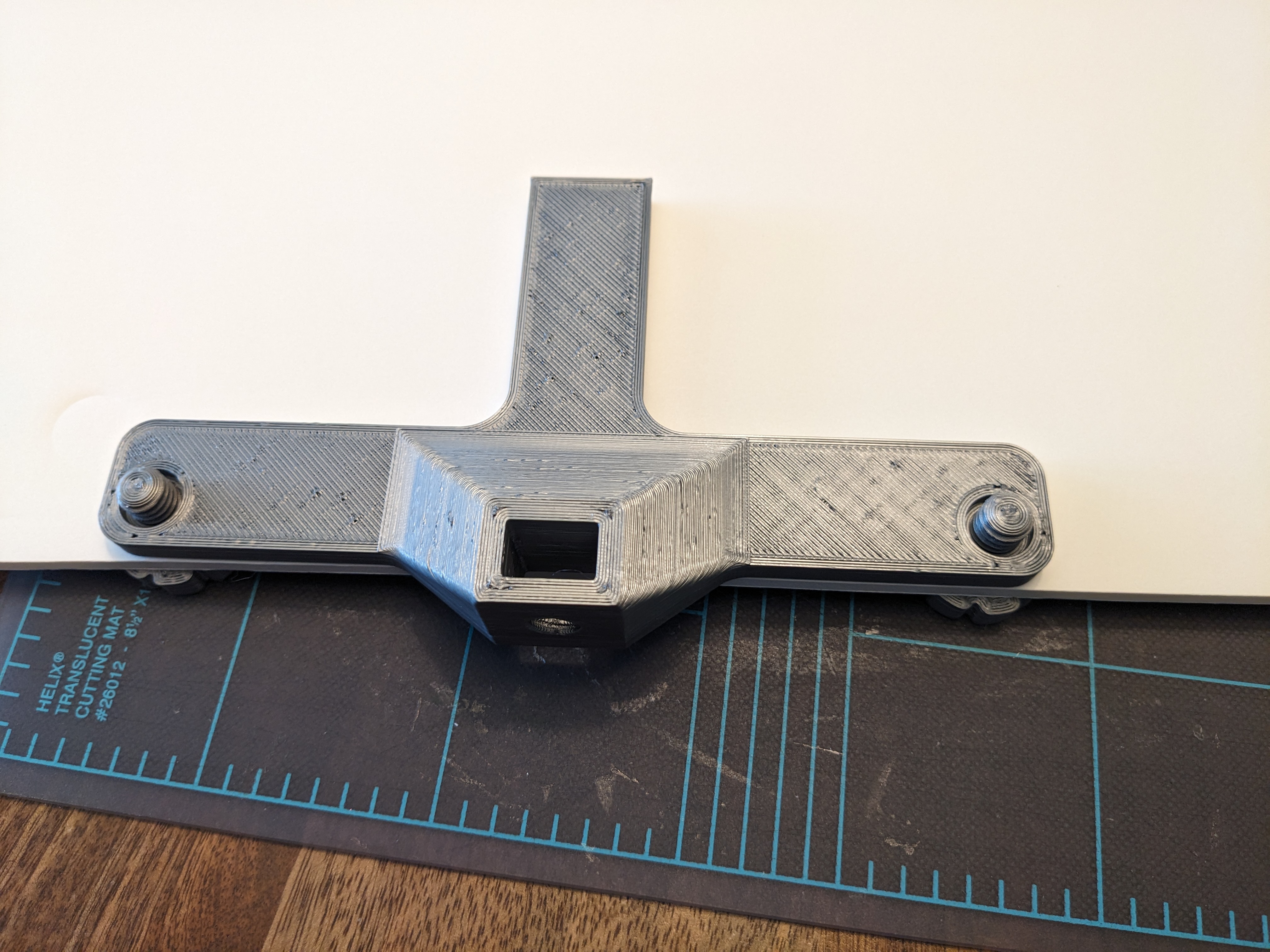

- Thread a printed thumbscrew into the hole in the bottom of the bracket. Do not screw it all the way in, there must be room for the rail to go into the channel first.
Step 4: Prepare the Middle Shield Assembly
The middle shield assembly keeps light other than light focused from the lenses from hitting the screen lower down on the rail as well as providing a thumbscrew to set the position of the bracket on the mounting rail.
- Cut a piece of foamcore posterboard as large as is practical, but at least as large as the piece used to make the screen in step 3 above. This will be the shield.
- This piece serves only as a shield – how flat it is doesn't matter, so you could use regular corrugated cardboard if it's fairly rigid.
- Align the bottom of the middle shield bracket with the middle of one edge of the shield.
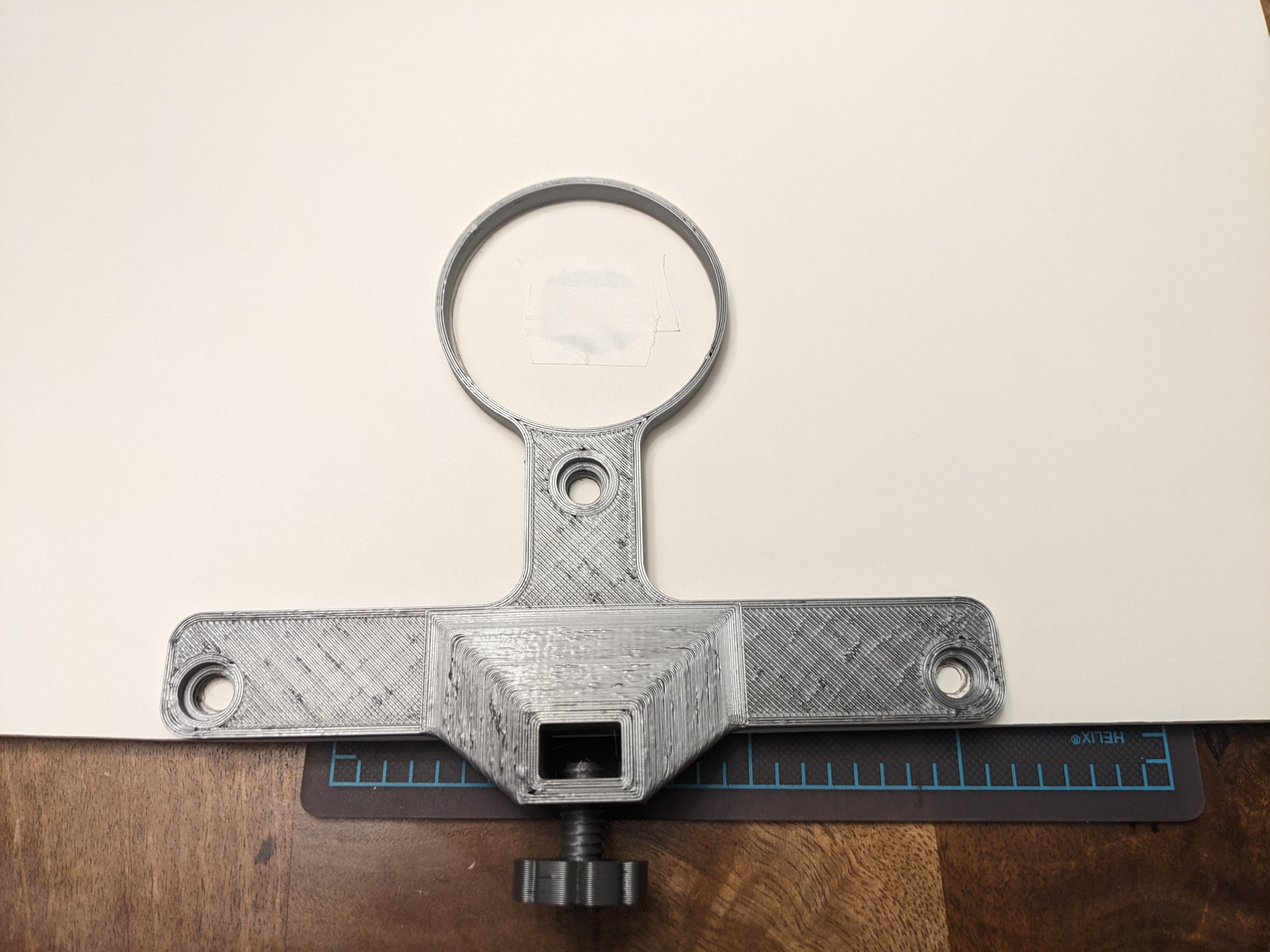
- Trace the three threaded holes as well as the large ring from the middle shield bracket onto the shield.
- Cut the holes you traced out of the shield. Make the cuts as close to perpendicular to the face as you can.

- Place the shield on the middle shield bracket and line up the holes.
- Thread three printed thumbscrews through the foamcore and into the middle shield bracket until the heads hold the shield securely.
- If the holes in the shield are slightly too small, you can twist the printed thumbscrew into them and it will cut its own threads in the foamcore.
- Do not over-tighten the printed thumbscrews. This could bend the shield or crack the screws themselves!
- Make sure the large hole is aligned with the ring at the top of the middle shield bracket.
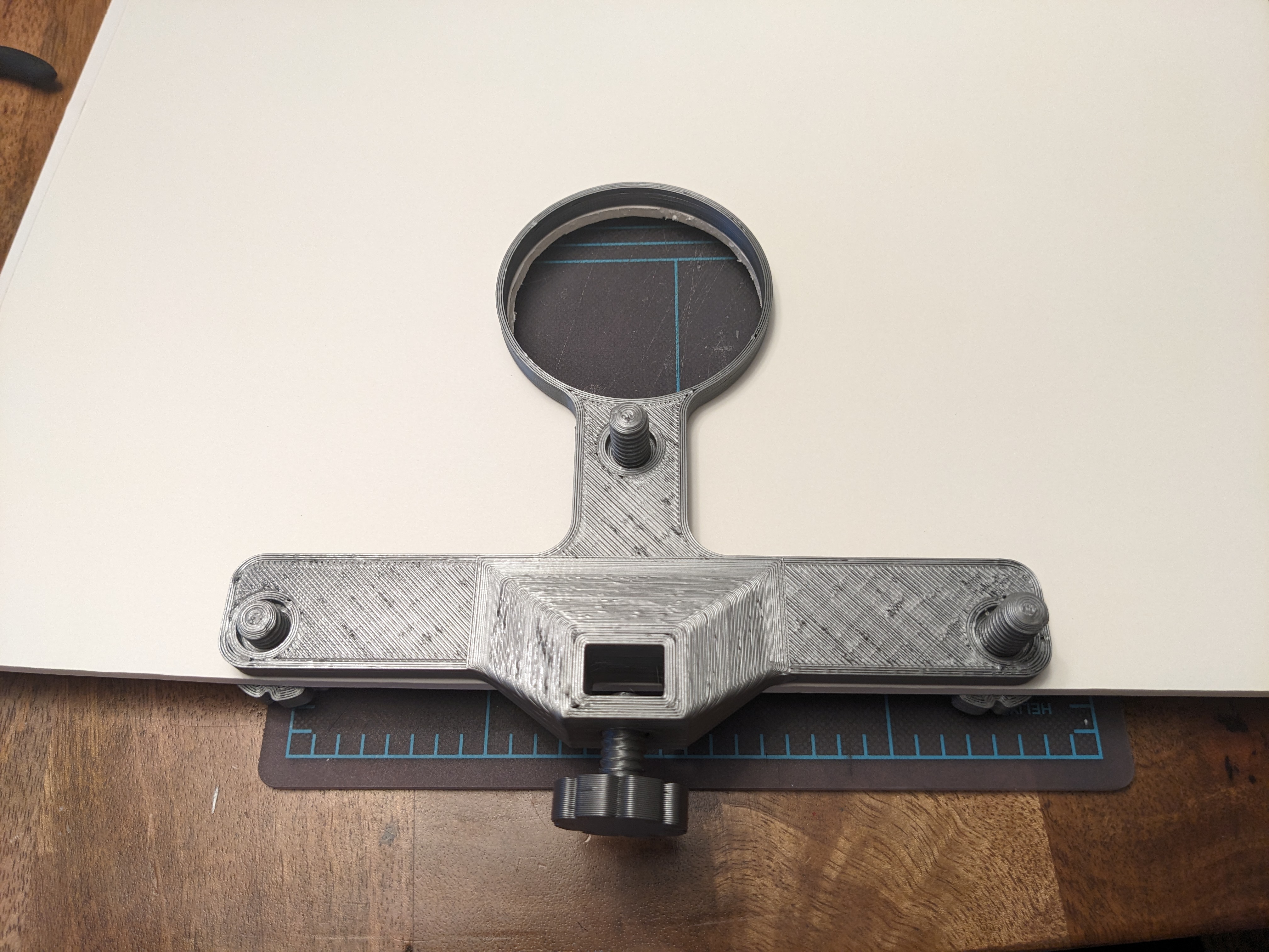
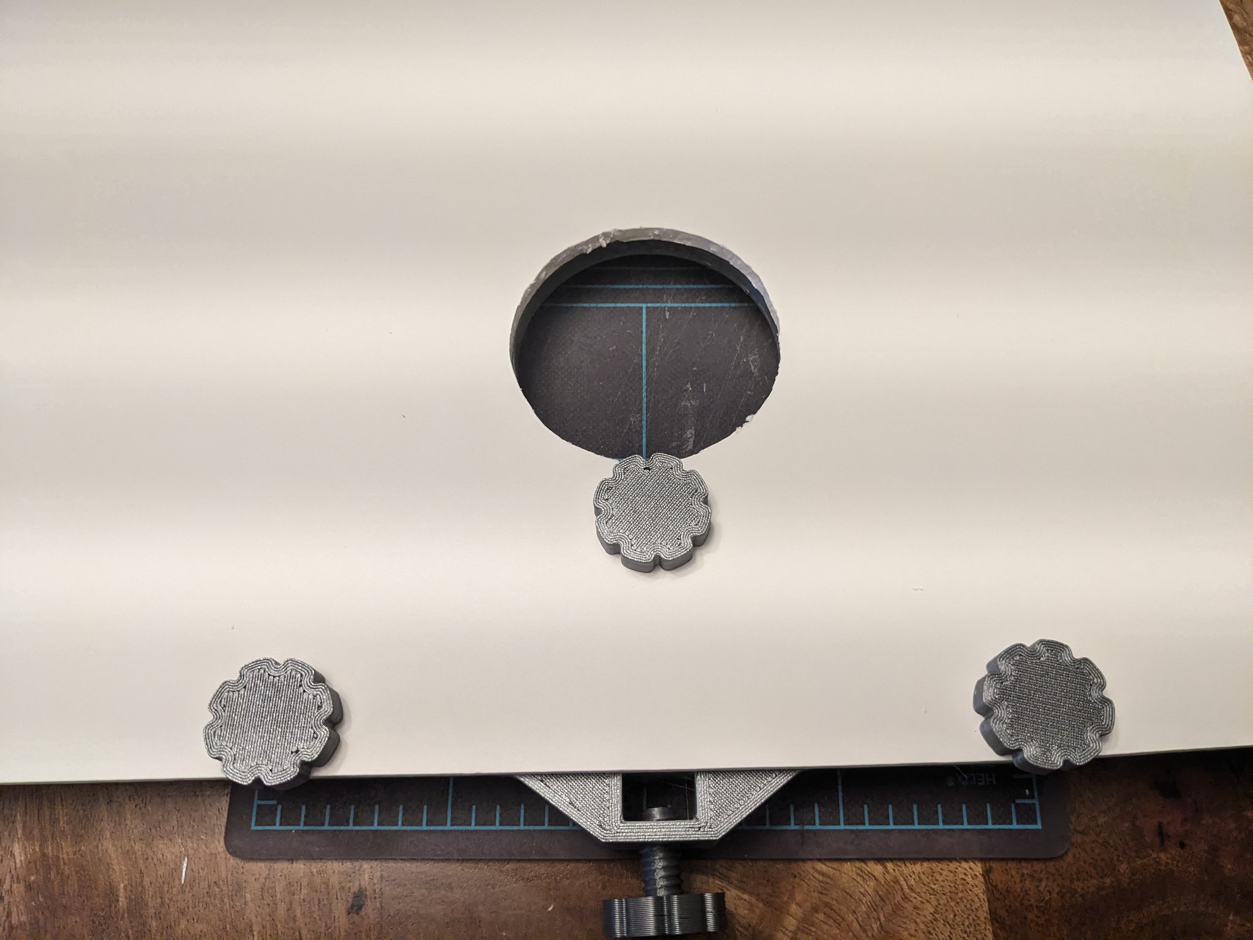
- Thread a printed thumbscrew into the hole in the bottom of the bracket. Do not screw it all the way in, there must be room for the rail to go into the channel first.
Step 5: Assemble the tripod mount
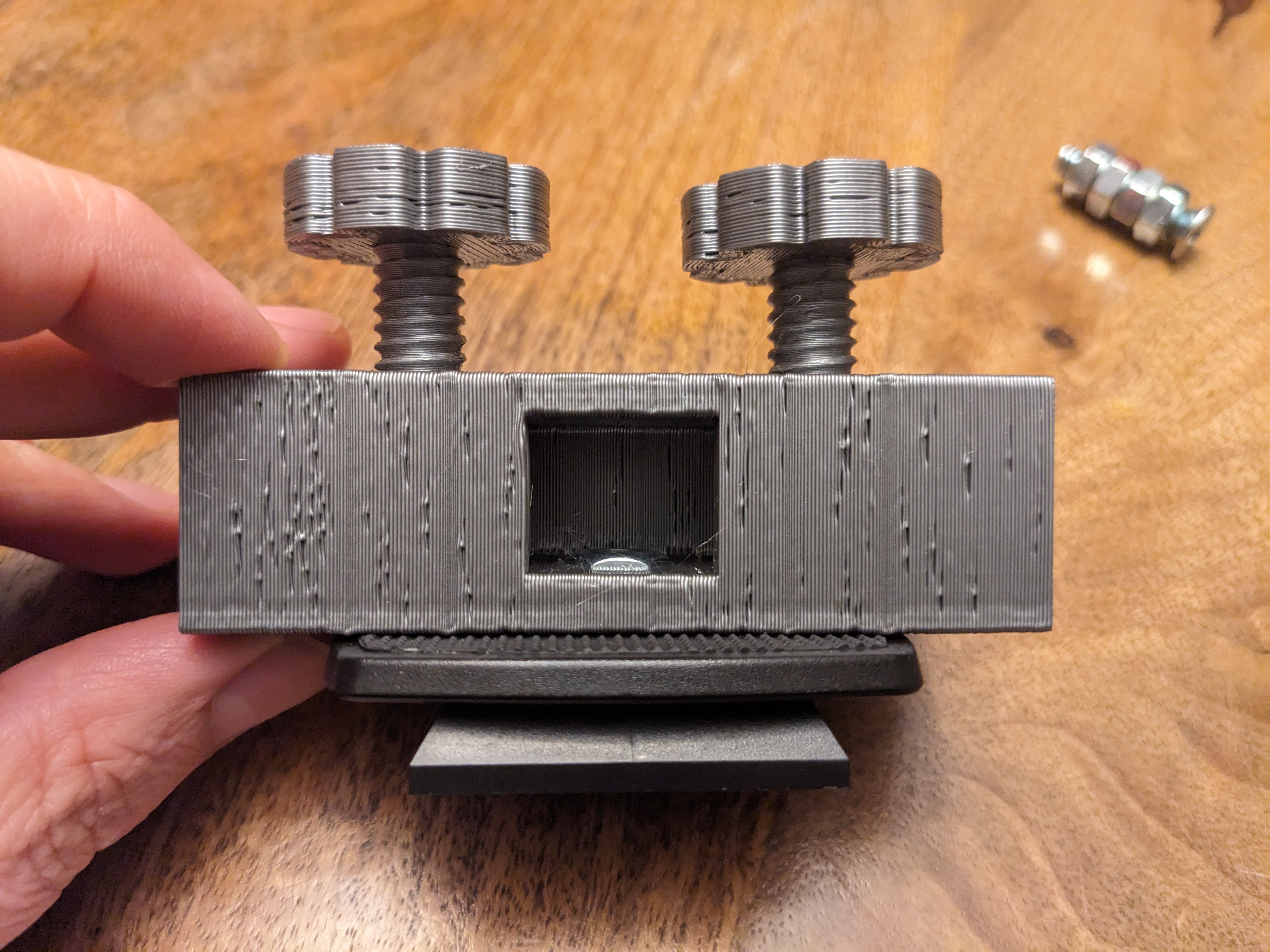
- The tripod bracket has a hole and two slots on one side – this is the side that attaches to the quick-release plate for the tripod. The slots are there to capture an anti-rotation pin if one is present on the tripod. The other side has two threaded holes for printed thumbscrews to secure the bracket on the rail.
- Slide a 1/4-20 nut into the nut depression inside the channel. Use the screw-pulling technique to pull it all the way down.
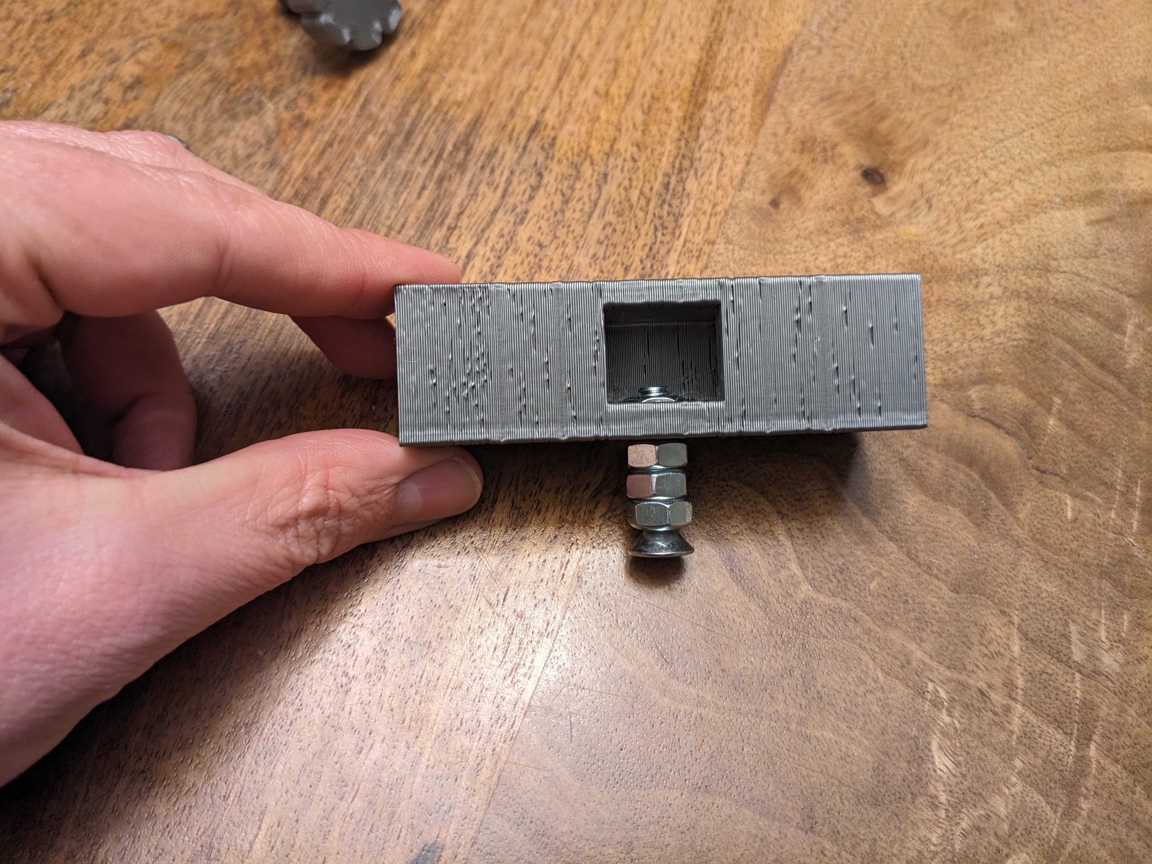
- Remove the pulling screw and thread the 1/4-20 screw from the tripod quick-connect plate into the nut.
- Screw two printed thumbscrews into the threaded holes on the other side of the bracket.
- They should not protruded into the channel more than 3mm to allow clearance for the rail. This part is mounted “upside down” from the other brackets, so the thumbscrews will contact the top of the rail, not the inside of the channel.
Step 6: Assemble the parts on the rail
In this step, we will mount everything on the rail and put it on the tripod.
NOTE: The rail brackets each slide onto the rail and are held in position by tightening the printed thumbscrew. They only need to be tightened enough to keep the brackets from sliding on the rail. Do not overtighten the printed thumbscrews, or they may break!
UPDATE: after using more, moved the tripod bracket to the top end of the rail worked better. The listing below has been updated.
- Slide the five rail brackets onto the mounting rail in the order listed below. The position of the brackets along the rail is not important and will be adjusted during alignment.
- tripod rail bracket
- the tripod quick-release plate should be toward the open side of the “C” channel of the rail, and the two thumbscrews should face the closed side.
- It does not matter which end of the bracket is closer to the primary lens assembly. It is symmetric.
- Tighten both thumbscrews so that the tripod bracket does not slide on the rail.
- primary lens assembly
- Position the bracket with the lens pointed toward the end of the rail – the lens points toward the sunward end of the rail
- The thumbscrew should be on the open side of the rail so that it passes inside the “C” channel of the rail.
- Tighten the thumbscrew so that the primary lens assembly does not slide on the rail.
- middle shield assembly
- Position the shield facing the sunward end of the rail.
- The thumbscrew should be on the open side of the rail so that it passes inside the “C” channel of the rail.
- Tighten the thumbscrew so that the middle shield assembly does not slide on the rail.
- Barlow lens assembly
- Position the bracket with the lens pointed toward the sunward end of the rail.
- The thumbscrew should be on the open side of the rail so that it passes inside the “C” channel of the rail.
- Tighten the thumbscrew so that the Barlow lens assembly does not slide on the rail.
- screen bracket
- Position the screen facing the sunward end of the rail.
- The thumbscrew should be on the open side of the rail so that it passes inside the “C” channel of the rail.
- Tighten the thumbscrew so that the screen assembly does not slide on the rail.
- tripod rail bracket
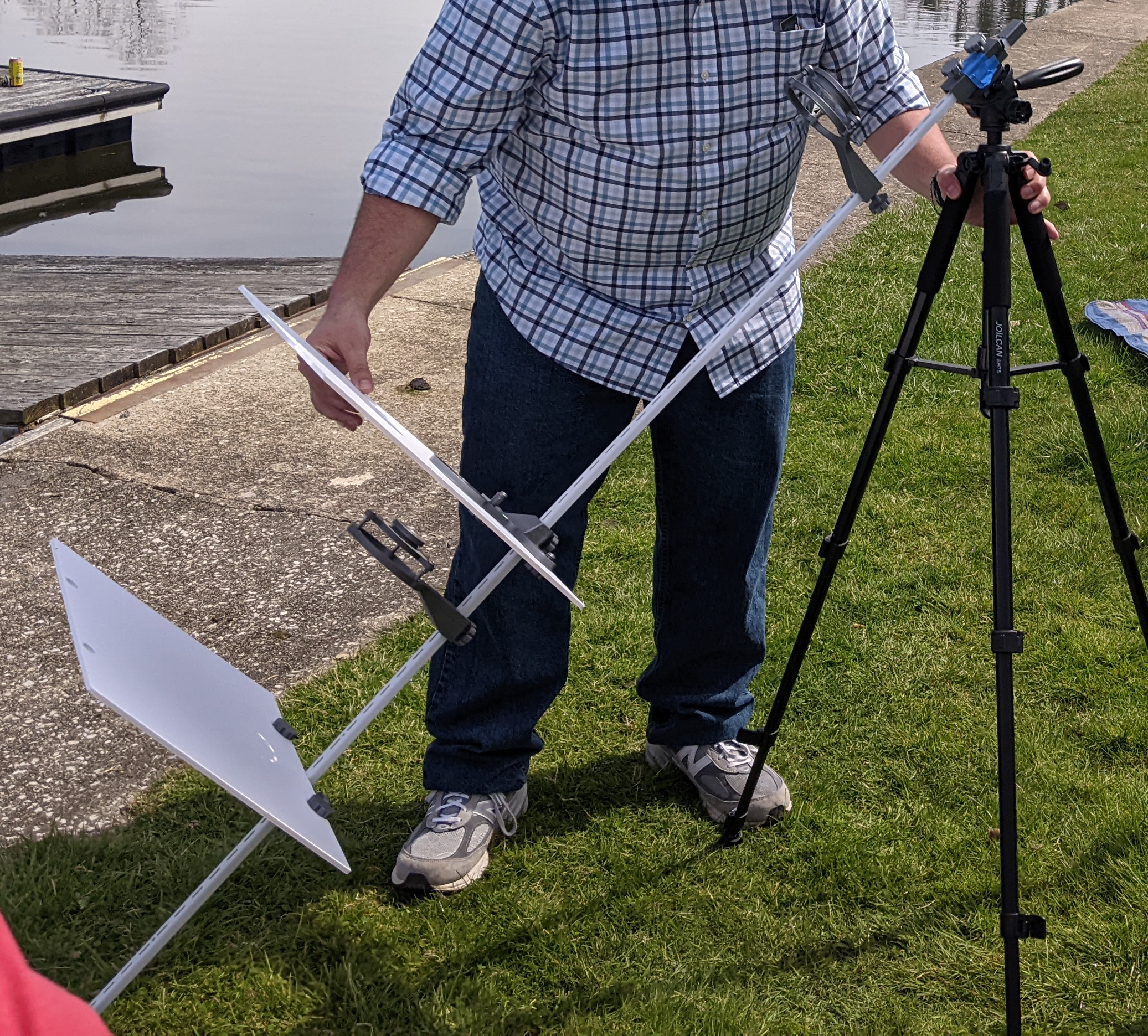
- Slide an end cap on each end of the rail so that it is tight. The inside of the end cap is wedged to grip the end of the rail.
Step 7: Attach the rail to the tripod
- Deploy the tripod so that it is stable and about 40"/1.1m tall.
- Using the tripod quick release that is attached to the tripod bracket, put the rail assembly on to the tripod.
- Angle the head of the tripod so that the sunward end of the rail (with the primary lens) is pointing upward about 45 degrees.
- Loosen the thumbscrews on the tripod bracket and adjust the position of the tripod bracket on the rail so that the end cap on the screenward end of the rail rests on the floor.
- Tighten the thumbscrews on the tripod bracket to secure the rail in place.
Step 8: Celebrate
- That's it! You did it! Now we can align the lenses.
Lens Alignment
- Take the SSV outside on a sunny day with a clear view of the sun on relatively level ground.
- Rough setup the components on the rail:
- Slide the primary lens assembly close to the sunward end of the rail
- Slide the screen assembly about 24" / 30cm from the bottom of the rail.
- You can position it lower for a larger, dimmer image, but only do this if the screen is very large. If you can't keep the sun aligned on the screen, move it up to make the image smaller. I found a 5" diameter sun image worked pretty well.
- Position the Barlow lens assembly and the middle shield bracket about halfway between the primary lens assembly and the screen bracket.
- By adjusting the height of the tripod, the position of the tripod bracket, and the angle of the tripod head, align the SSV roughly in the direction of the sun.
- The shadow cast by the primary lens assembly should roughly line up with the hole in the middle shield bracket and the Barlow lens assembly.
- Make sure the screen end of the rail is resting on the ground.

- The primary lens should make a bright dot of sunlight near the Barlow lens assembly. By adjusting the three screws on the primary lens assembly, adjust the aim of the primary lens so it strikes the center of the Barlow lens.
- Be careful not to unscrew the primary lens holder all the way!
- Adjust the position of the Barlow assembly on the rail until the image of the sun (a white circle) is sharpest on the screen.
- You should loosen the thumbscrew on the middle shield assembly and move it with the Barlow lens assembly.
- Slide the middle shield assembly up enough to gain access to the adjustment screws on the Barlow lens assembly. Use this to adjust the aim of the Barlow lens to center the image of the sun on the screen.
- You may have to repeat some of these steps to get the best image. If the image is too big or too dim, slide the screen assembly closer to the sunward end of the viewer and reset the Barlow lens bracket to adjust the focus.
- When you have a good image, tighten all the thumbscrews on the brackets. Use a permanent or paint marker to mark the location of both ends of the brackets on the rail for future reference.
Expect to fine-tune this procedure before the eclipse starts, but by getting everything set up ahead of time, you can verify the construction and get a good start.
During the eclipse, you will need to re-aim the viewer every few minutes to keep it aligned. You should not need to adjust the spacing of the lenses. The procedure I found simplest for this was as follows:
- Set the tripod up so that the viewer is aligned with the sun with the vertical screw-neck adjustment fully extended – this may require shortening the legs.
- As the sun moves out of view, rotate the rail by picking up the screenward end and moving it clockwise until the white dot from primary lens holder is aligned left to right with the center of the viewer.
- Lower the screw neck until the white dot is centered on the barlow lens.
- Check the positioning of the sun on the screen and adjust accordingly.
- View until the sun moves out, then repeat
You'll keep lowering the tripod as the sun moves (at least, I did), so when you get to the end of the vertical screws adjustment. Then you can collapse another section of legs and re-extend the screw.
Safe Solar Viewer for Eclipses
Publicado em 10 de abr de 2024
Gostou deste modelo? Crie uma conta grátis para salvar seus favoritos e voltar a eles depois.
Criar conta