Você está no 3DFinder
Buscamos em Thingiverse, MakerWorld e Printables ao mesmo tempo para te dar o melhor de cada uma.
Descrição
There's way too much information to decode the Matrix. You get used to it, though. Your brain does the translating. I don't even see the code. All I see is blonde, brunette, redhead.
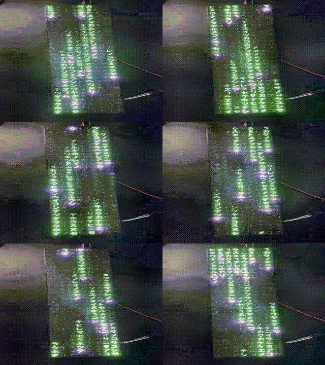
This is a simple gadget inspired by the popular movie "The Matrix". The gadget is a matrix of characters that are back-lit with a falling raindrop effect. The instru
ctions are split in two parts
- How to print and assemble the gadget using the provided files;
- How to customize the design to you needs.
The reason why the customization comes last is that… well, it's a bit “crafty” and I consider it to be for “enthusiasts” ;)
Required Materials and Software
Materials
- Black and white PLA (to be clear: 2 filaments, not one that is black&white!)
- LED matrix (I used a 32x8 matrix of WS2812B ARGB LEDs sold by BTF-Lighting on Amazon)
- Arduino Nano or equivalent
- Power Supplier (optional, see wiring instructions)
Software
- Cura (other slicers could be ok if they allow transforming a PNG to a 3D model)
- Arduino IDE
If you want to customize the design:
- Inkscape with the simple scripting extension
- FreeCAD
Part 1: DIY!
Printing
Case
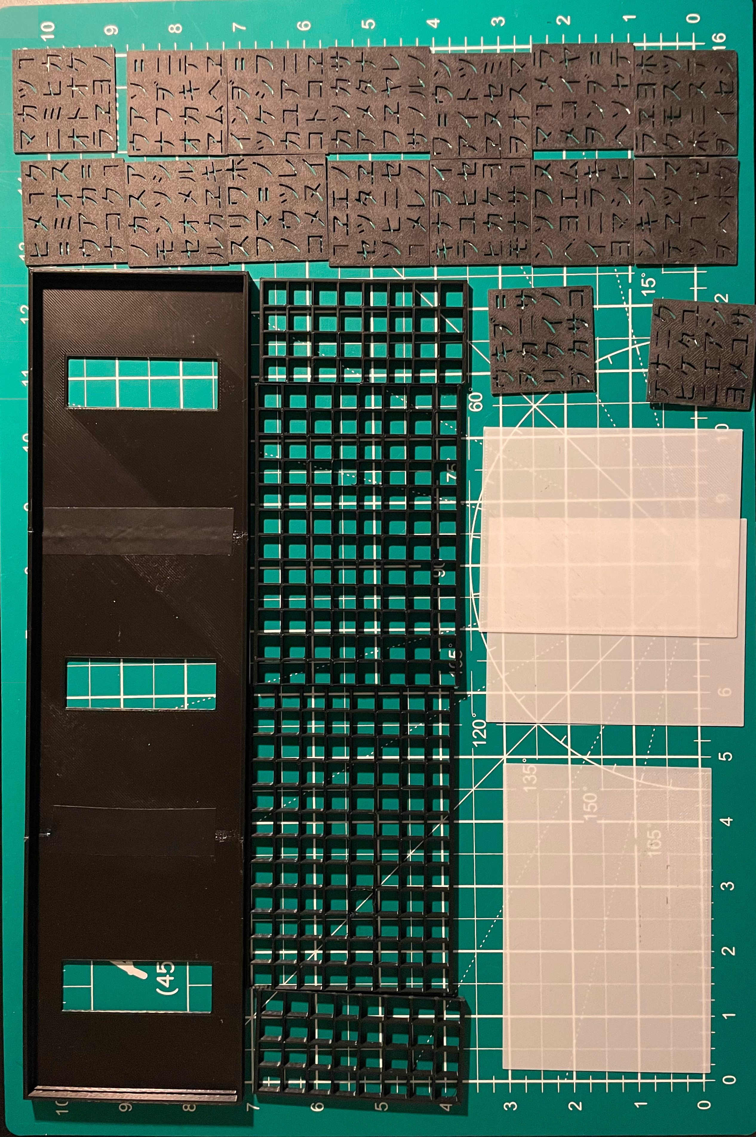
For a "standard" 32-by-8 matrix, you need to print:
- Two copies of matrix-box-ext.stl and one of matrix-box-int.stl
- Two copies of matrix-grid-4.stl and two of matrix-grid-12.stl
- Two copies of matrix-diff-ext.stl and one of matrix-diff-int.stl (use white PLA for these!)
Remember to use black PLA for all parts but the diffuser - which must be white, to let some light pass through. These parts can be printed using Cura's standard quality preset (0.2mm layer height with a 0.4mm nozzle).
Letter Panels
Download the characters.zip archive and extract the 16 PNG images containing the characters. One by one, you will need to import them in Cura, generate a 3D model and slice it. Follow these steps:
- From Cura, click on the import button and select one PNG.
- A window named Convert Image should pop up. Enter the following settings:
- Height: 0.8mm
- Base: 0.0mm
- Width: 41mm
- Depth: leave it as is (calculated by Cura)
- "Lighter is higher"
- Color Model: Linear
- 1mm Transmittance: 50.0%
- Smoothing: 1
- Select Cura's standard quality preset and update the following:
- Walls → Wall Thickness → Wall Line Count: 1
- Material → Build Plate Temperature: 60°C
- Speed → Initial Layer Speed: 10.0mm/s
Print the parts. I recommend sanding the sides and faces of these tiles for a nicer look.
Assembly
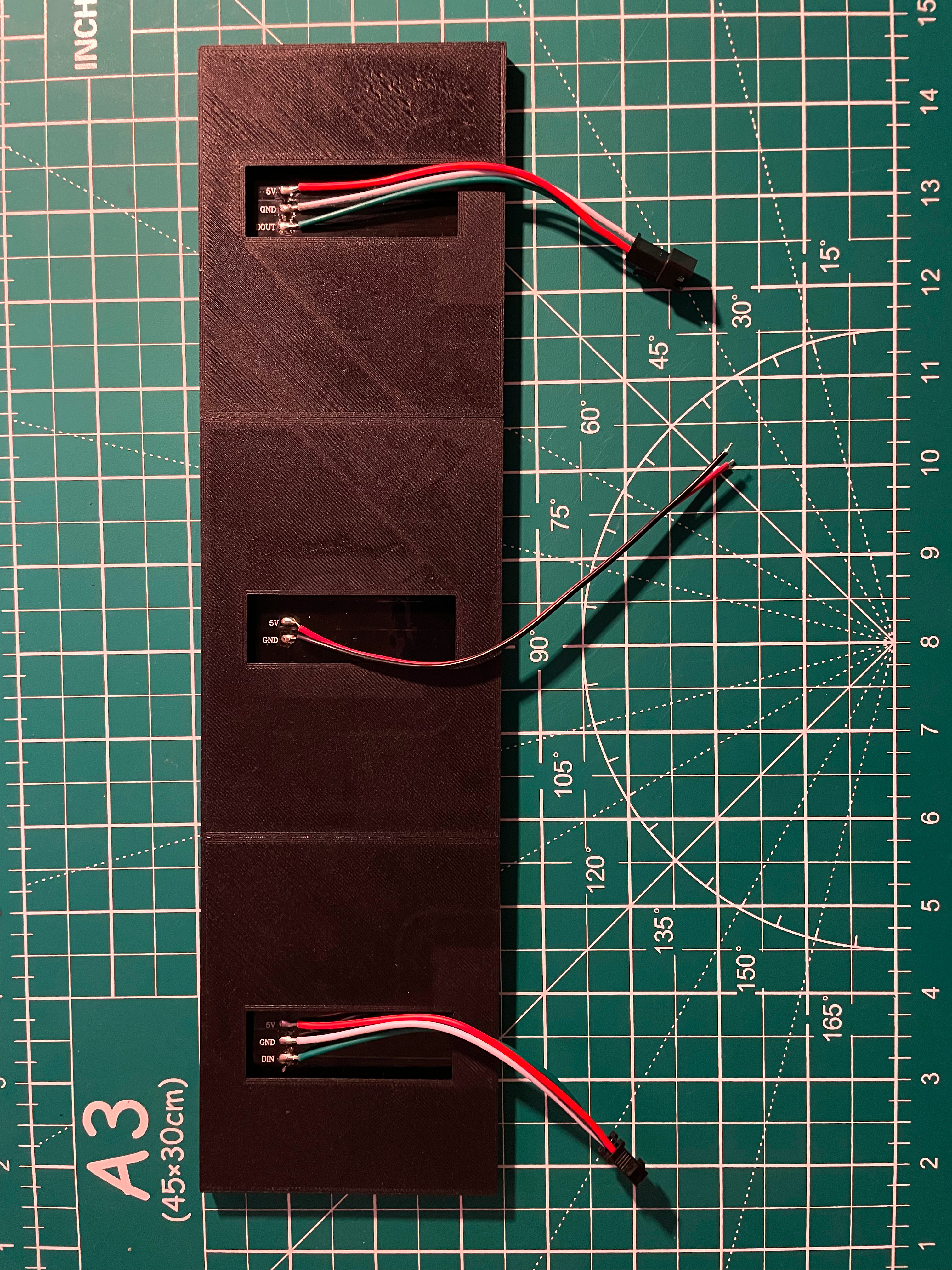
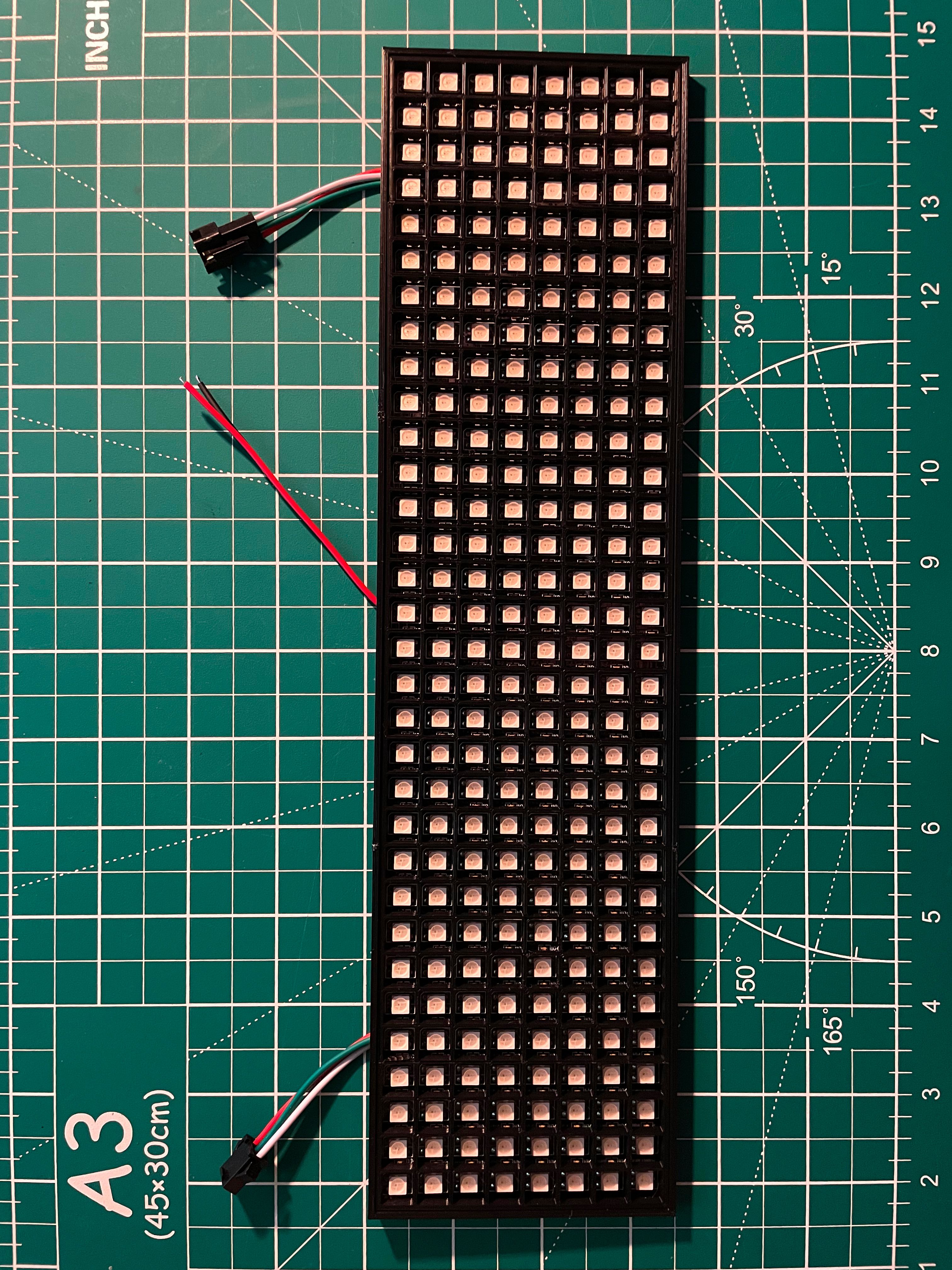
- Assemble the box, joining the three parts with some glue and/or tape.
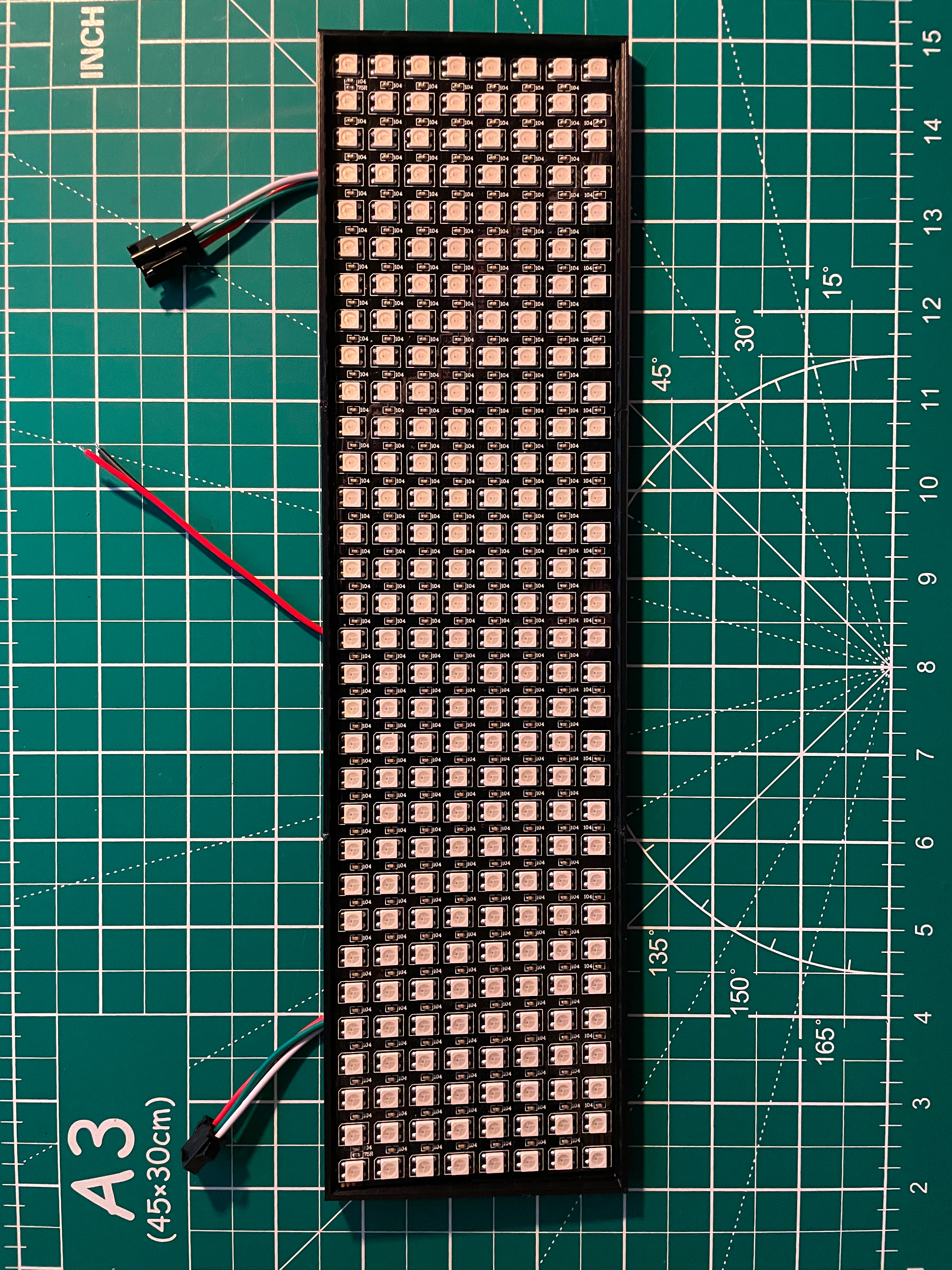
- Insert the LED matrix inside it.
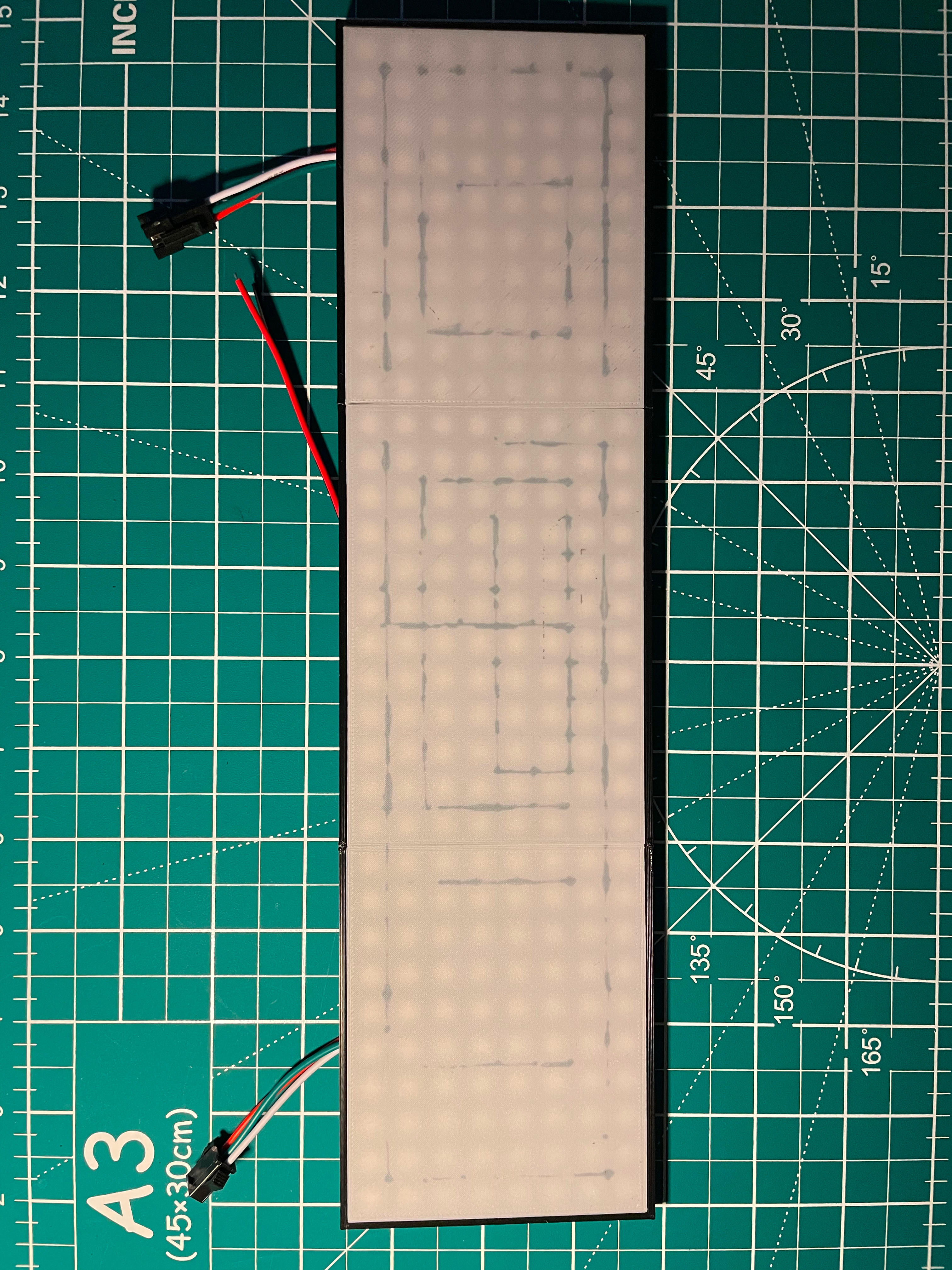
- Fit the grid parts on top of the LEDs. The longer ones (both 12 cells-long) are to be placed in the middle. The shorter ones (4 cells-long) are to be placed in the extremities. Note that the short ones have a proper orientation! If you observe them carefully, one side is thicker. Such side is to be place in contact with the box. The thin sides should touch the 12 cells-long grid pieces instead.
- Glue the three white sheets of the diffuser on top of the grid. My recommendation is to place the shorter ones on the extremities.
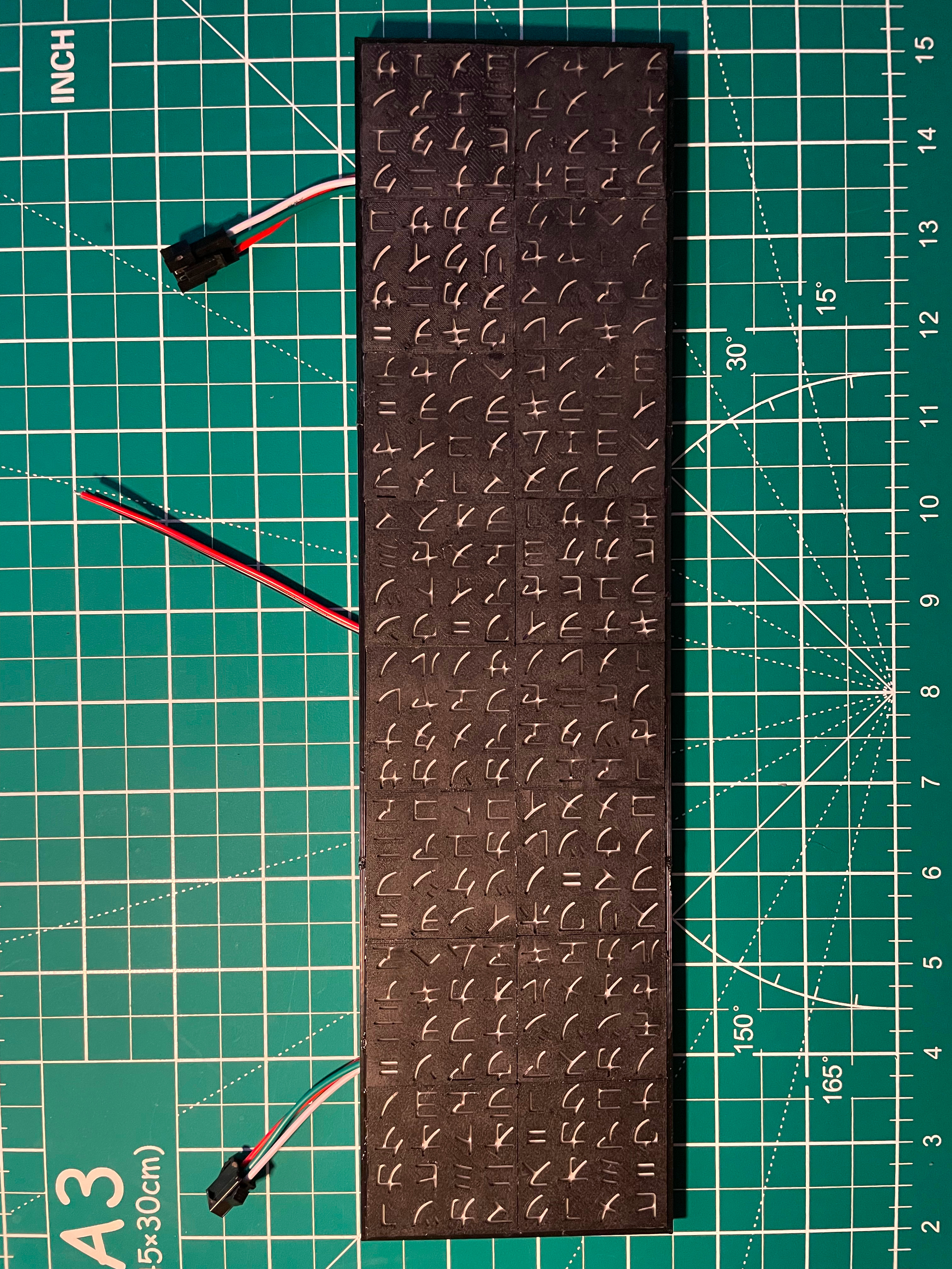
- Glue the black tiles on top of the diffuser. Note that they have a specific order! Check the konkani.svg file to see how they are to be placed.
Flashing & Wiring the Arduino
Unzip the archive that contains the code and open the main file, with “.ino” extension, in the Arduino IDE. Install [FastLED](https://fastled.io/) by clicking on Tools → Library Manager. Type FastLED in the search bar and click on the Install button.
You can now customize the script by changing the following constants:
- Hardware definitions:
DATA_PINSis the number of the digital pin(s) that will be connected to the matrix to control the LEDs. By default, the program assumes that you have a single matrix whose data line is connected to digital pin 3.LED_TYPEis the chip type of the LEDs on the matrix. Check the specs of your LED matrix and the documentation of FastLED to know which value you should be using.COLOR_ORDERthis is again linked to the type of chip that controls the LEDs. Check FatLED's documentation for more information.
- Effect settings:
REFRESH_PERIOD_MS: this sets the rate at which LEDs are updated. In practice, colors are refreshed everyREFRESH_PERIOD_MSmilliseconds. High values will "look" ugly, low values will be “CPU” intensive. I had good (in my opinion) results with 20ms.MAX_BRIGHTNESS: white value of a droplet. I think a value around 50 looks good - and allows to save power with respect to a full 255 brightness level!DROPLET_MIN_RESPAWN_DELAY_MSandDROPLET_MAX_RESPAWN_DELAY_MS: bounds for the time (in milliseconds) to wait before bringing a droplet that reached the bottom of the matrix back on the top. The actual value will be selected each time at random between these values.DROPLET_MIN_FALL_DELAYandDROPLET_MAX_FALL_DELAY: control the speed of the droplets. Every time a droplet is placed back on top of the matrix, the time required to fall from one row to the following one is selected at random in the interval betweenDROPLET_MIN_FALL_DELAYandDROPLET_MAX_FALL_DELAY.DIM_INTERVAL_MS: each droplet leaves a trail behind that slowly fades by gradually dimming each LED it touched. This constant decides how fast the LEDs are dimmed (a lower value means that the trail is visible for a shorter period).DROPLETS_PER_COLUMN: how many droplets, at once, can be present in a single column.
- Color settings:
DROPLET_COLOR: the color of the falling droplet. By default, this is a “pure white” color, which I think works well with many color schemes.COLOR_TRAIL: the color that is left by a droplet. When the droplet moves to another pixel, it leaves a "trace" behind whose color is initiallyCOLOR_TRAIL.COLOR_REST: "background" color of the matrix, when not lit by a droplet or its trace. Set it to (0, 0, 0) to have the matrix unlit when "at rest" (requires less power consumption). You can use small values - such as (0, 2, 0) - to keep all characters glowing after the trace of a droplet faded. Due to the very simple math used to simulate the fading trails, the RGB components of this value must all be smaller (or at most equal) to those ofCOLOR_TRAIL.COLOR_DECAY: color to subtract from each LED at each dim cycle. This is the cause of the "fading effect". To change the rate at which the trail fades, I recommend to keep the values of this variable as small as possible and play withDIM_INTERVAL_MSinstead.
- Matrix settings:
ROWS_PER_LED_MATRIXandCOLS_PER_LED_MATRIX: number of characters in the matrix.ORDERING: how LEDs are physically connected to each other (this depends on how the LED matrix that you purchased was manufactured). As a guideline, refer to the following sketch of a 3x3 matrix in which the numbers show the order in which LEDs appear:
ROW_MAJOR   COLUMN_MAJOR   SNAKE_HORIZONTAL   SNAKE_VERTICAL
  1 2 3        1 4 7            1 2 3             1 6 7
  4 5 6        2 5 8            6 5 4             2 5 8
  7 8 9        3 6 9            7 8 9             3 4 9
After you adapted the parameters above to your needs, it's time to load the firmware on the microcontroller. To flash the Arduino, plug it to your PC, select the correct model type and COM port and click on the "upload" button.
Wiring is very simple:
- Connect the chosen data pin (the one specified by
DATA_PINS) to the corresponding wire of the matrix. - Connect the ground pin of the Arduino, the ground wire of the matrix and the ground terminal of your power supplier together.
- Connect the positive terminal of your power supplier to the corresponding wire of the matrix.
In case of any doubt, refer to the schematic below. Yes, it uses a potato as 5V power supplier. No, I have not tested it in real life.
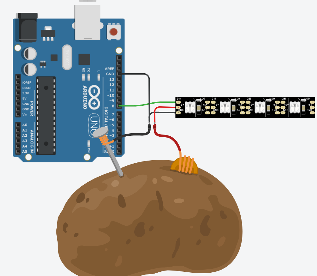
Note that if you are not pushing the brightness of the LEDs to high values and you are not lighting the whole matrix up, you may also power the LEDs directly from the Arduino board. In this case, get rid of the potato from the schematics above, and simply connect the 5V pin to the 5V wire of the matrix.
(New!) Using multiple matrices
The code now allows to pilot not just one LED matrix, but up to 8 in parallel! Unfortunately, they must be identical matrices - same chipset, same number of rows, same number of columns. Hopefully, this isn't a major limitation.
Configuring multiple matrices is simple: just set DATA_PINS to… the pins you are going to use for the matrices! As an example, if you want to control three matrices via the digital pins 6, 10 and 13, just make sure that the line #define DATA_PINS 3 is changed into #define DATA_PINS 6, 10, 13 - that's it! Also, be sure that ROWS_PER_LED_MATRIX and COLS_PER_LED_MATRIX are set to the number of rows and columns of a single matrix. As an example, if you have three 8-by-4 matrices stacked in parallel to form a wider 8-by-12 matrix, set ROWS_PER_LED_MATRIX to 8 and COLS_PER_LED_MATRIX to 4 (not 12!) since these are the dimensions of the individual matrices.
Wiring should also be trivial: make sure that all 5V lines are connected together, same goes for the GND lines. Then, connect each data line to a corresponding digital pin specified in DATA_PINS.
Part 2: Custom Design (optional)
Say that you don't like my ready-to-print design. Well, SHAME ON YOU! Jokes aside, you can try to alter the design of the gadget to your liking. There are mainly two things that you can do:
- Create an alternate set of character panels
- Change the dimensions of the matrix
I will explain how to do the two things at once.
New Characters Panels in Inkscape
Create a new document in Inkscape. Make sure that the simple scripting extension is installed, then open the scripting window via Extensions → Render → Simple Inkscape Scripting. In the window, press the button to select a Python File and choose the matrix_inkscape.py script (it is one of the downloadable files of this project). Then, paste the following script:
konkani = "゠アイウエオカキクケコサシスセソタツテトナニヌ" \
          "ノヒフヘホマミムメモヤユヨラリルレワヱヲンヺヿ"
create_matrix(rows=5, cols=3, cell_size=10, spacing=1, border=1, max_size=4, konkani=konkani)
Press on the Apply button: this will create a 5-by-3 matrix, with each cell being 10mm wide, with an additional border of 1mm around the matrix. The characters will be at most 9mm wide - equivalent to cell_size-spacing. Two sub-blocks are created, one with size 4-by-3 and the other 1-by-3, since the parameter max_size is set to 4 - which prevents sub-blocks with more than 4 rows/columns to be created.
Notes:
- The generation can take up to several minutes depending on the number of characters.
- To keep compatibility with the CAD file, my recommendation is to change only the number of rows and columns, but feel free to experiment.
- You can choose other characters by setting the konkani variable to something else. However, keep in mind that you cannot print characters with holes. This is the reason why I avoided Latin letters and numbers.
After the generation, select all objects (CTRL+A) and click on Path → Object to Path. With all objects selected, click on Object → Flip Horizontal. Finally, for each sub-block: select the characters and the white background rectangle, then choose File → Export and export the selection as a PNG file. These files replace those contained in characters.zip. To print them, follow the same instructions.
Update the FreeCAD Model
If you changed the characters panels, you may need to update the container as well. This is the case if you:
- Changed the number of rows or columns
- Changed
cell_sizeorborder
To update the model, open the file matrix.FCStd in FreeCAD and open the spreadsheet. Change the parameters as needed. In particular:
- The Cell size parameter should match the
cell_sizevalue used in Inkscape - Rows and Columns should match
rowsandcols(duh!) - Grid border should match
border
Feel free to experiment with other parameters - at your own risk.
Now, go back in the 3D view, select and export one-by-one the parts in STL format (box, diffuser and grid). Note that it is likely that these parts will be too large for your print area. Fret not: you can "cut" them by changing two parameters in the spreadsheet. As an example, In my case I had a 32-rows-long matrix, and I decided to:
- Set Cut from row to 0 and Rows to cut to 10. I exported the box and diffuser parts to STL as matrix-box-ext.stl and matrix-diff-ext.stl
- Set Cut from row to 10 and Rows to cut to 12. I exported the box and diffuser parts to STL as matrix-box-int.stl and matrix-diff-int.stl
- Set Cut from row to 0 and Rows to cut to 4. I exported the grid as matrix-grid-4.stl
- Set Cut from row to 4 and Rows to cut to 12. I exported the grid as matrix-grid-12.stl

Gostou deste modelo? Crie uma conta grátis para salvar seus favoritos e voltar a eles depois.
Criar conta