Você está no 3DFinder
Buscamos em Thingiverse, MakerWorld e Printables ao mesmo tempo para te dar o melhor de cada uma.
Descrição
7 segment LED clock. Simple to print and to setup.
Functions:
- RGB LED clock with web configuration page.
- The time and date value can be displayed in different colors.
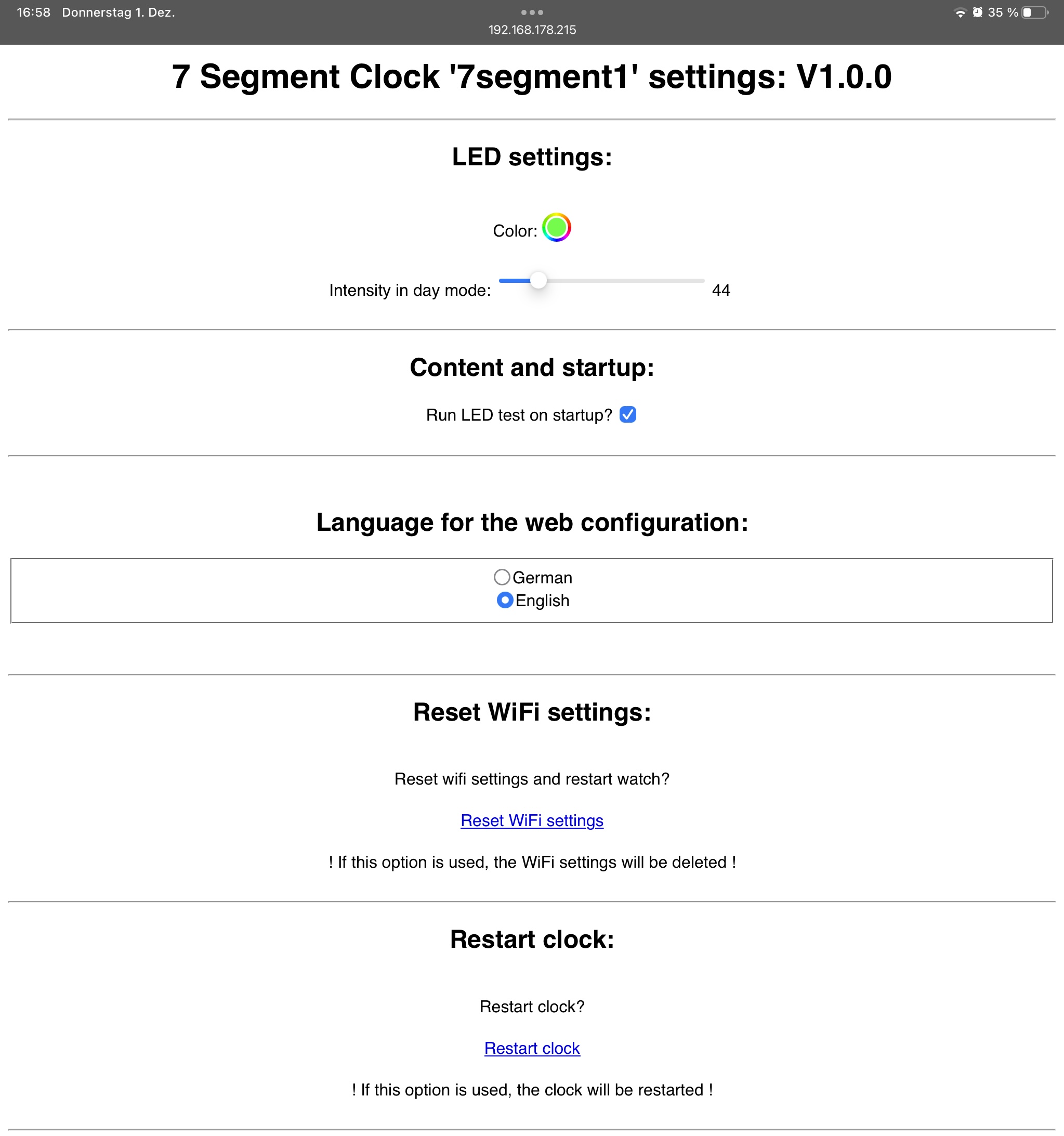
- The colours and intensity can be controlled with the internal web page.
- The device is hooked up to your network with the WiFi Manager.
- During startup the current IP-address is shown on the display.
- During startup an initial LED test is performed that can be turned off in the settings.
- During night times the LED intensity can be reduced to set to 0. ***
- The 2 points blink every second. They and be turned off or set to on permanently. ***
- The size of the clock is 205.5 x 105.5 x 45.5 mm and fits well on 210x210mm print beds.
*** = work in progress
Video:
Parts used:
- 1x Arduino ESP8266 D1 mini
- 30pcs LED chips WS2812B Ø9.75mm
- 1x Barrel jack for power input Ø12mm
- 1x 5V / 2A power supply with barrel jack connector
- 1x Transparent super glue to glue the white front parts into the case
- 1x Some wires in different colors
- 7x M3x20mm screw
Wiring the parts:
- The single LED chips are soldered together to a single chain.
- The 2 point LEDs are at the end of the chain as shown in the pictures.
- Connect the 5V pin of each LED to the next LED as numbered from LED 0 to 29.
- Connect the GND pin of each LED to the next LED as numbered from LED 0 to 29.
- Connect the DOUT of each LED to the next LED as numbered from LED 0 to 29.
- The DOUT pins of LED 29 stay unused.
| ESP8266: | 1st LED = LED "0": | Barrel jack: | Color: |
| 5V | 5V | +5V | red |
| G | GND | GND | white |
| D2 | DIN | green |
LED order:
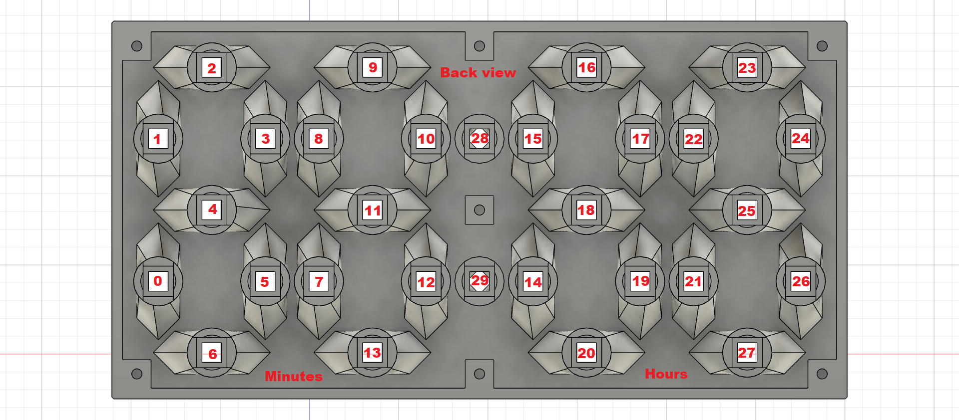
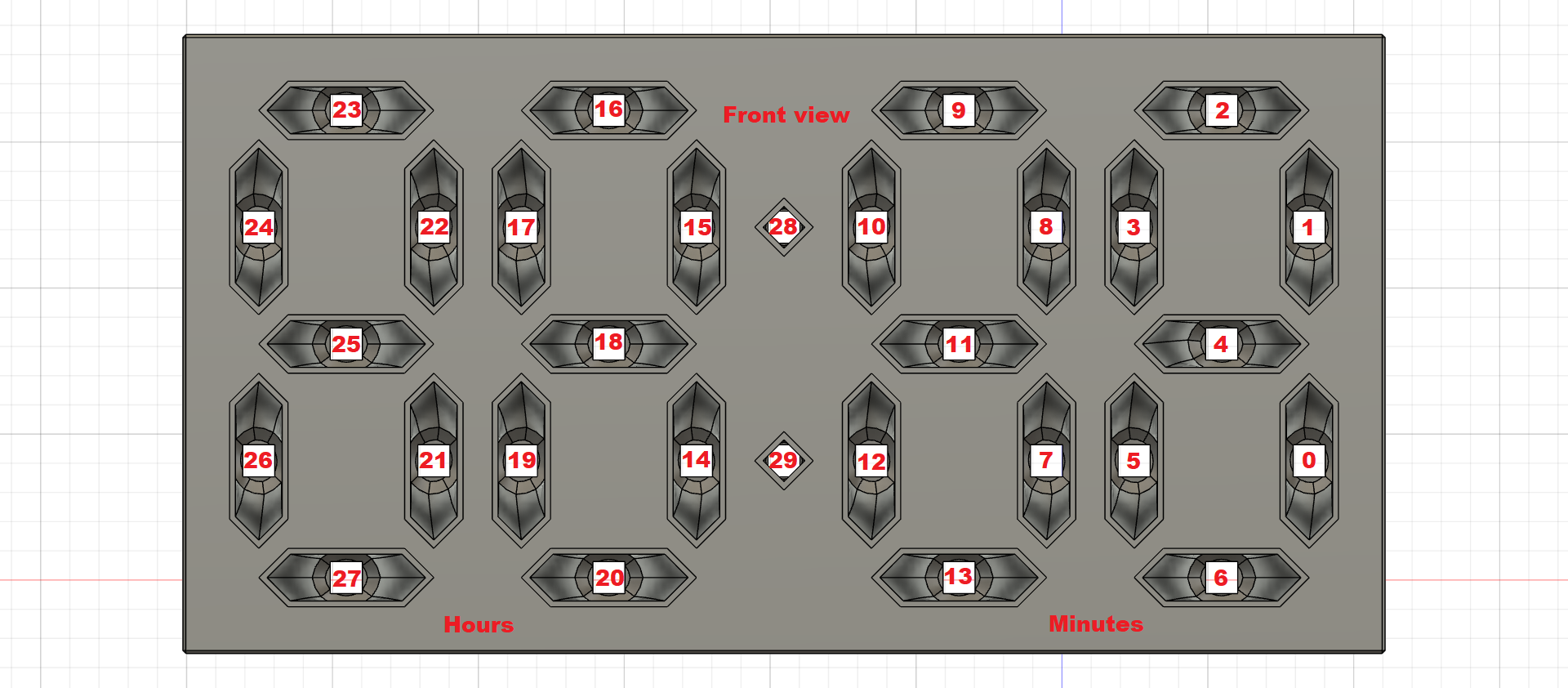
Mounting the LED chips:
- Press the LED chips in their holders as shown in the picture. No glue needed.
- Check the orientation of the LED chips again before soldering the wires to them.
- Add solder to each pad to add the wires later to them more easy.
- Add solder to each wire end too before soldering them onto the LED pads.
- Check that each solder point looks nice and shiny to avoid “cold“ solder connections that might cause problems later in the use…
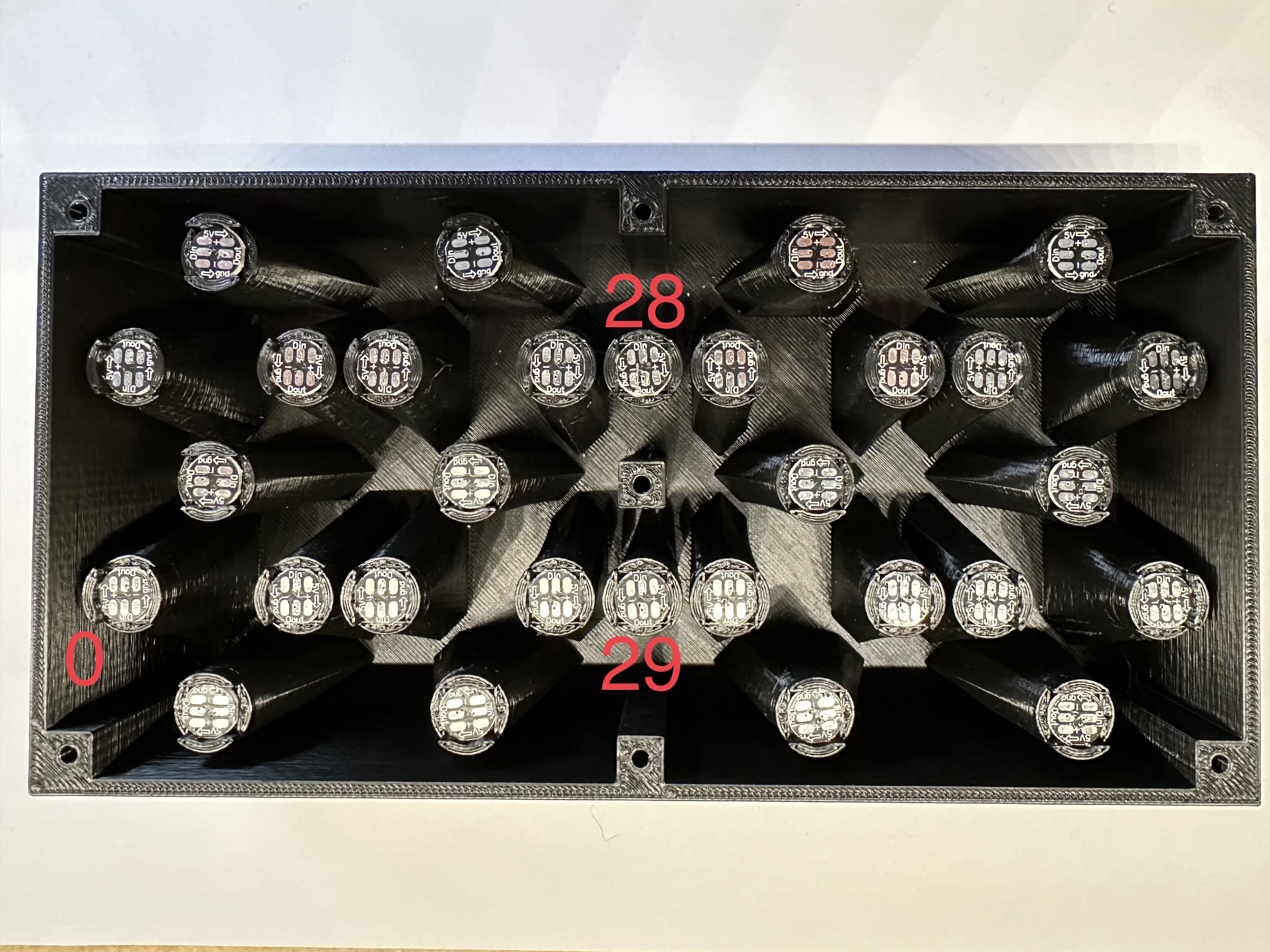
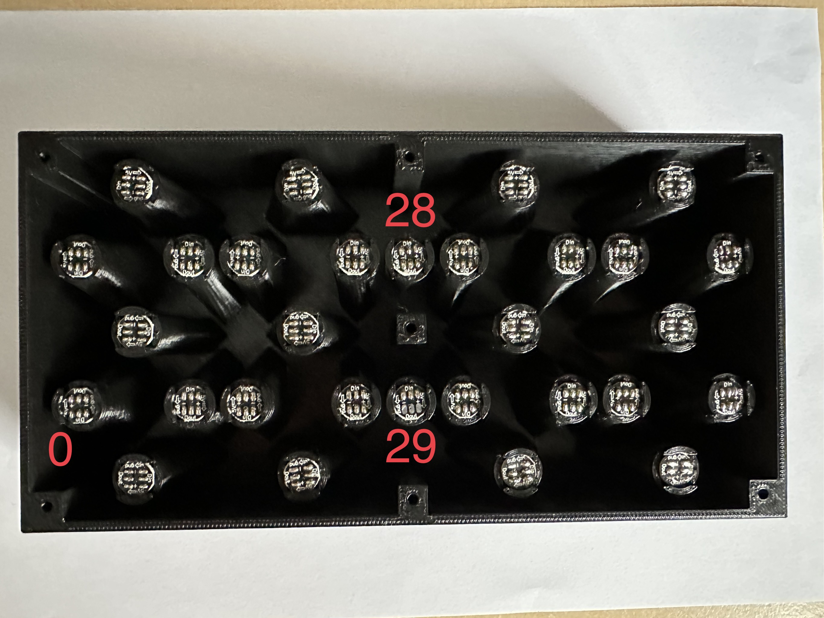
Code:
- The needed code can be found in my GitHub repository.
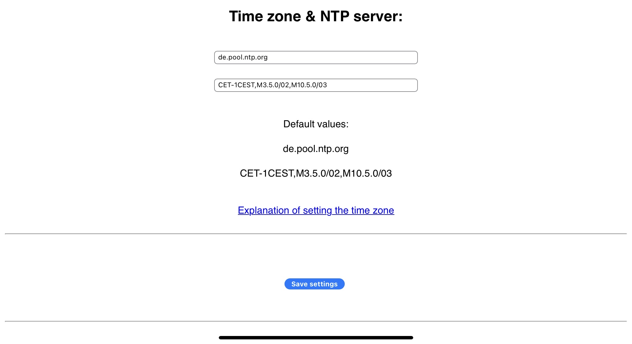
Web configuration:
Printing instructions:
- Textured sheet used
- 0.2 quality profile used for the “segment” and “point” parts
- 0.3 draft profile for the “case" and the “lid” part
- Supports needed for the “case” part from the print bed
- 5mm brim needed for the “case" and the “lid” part
- Print the base part in a darker color
- Important: Print the “segment” and “point” parts in white color
Notes:
- Complete code will follow… Currently in progress… Basic version online. =)
- The next version will be able to install without the need of glue.
- Instead of the single LED chips I would like to use LED stripes, because the wiring takes quiet some time…
Happy printing :)

72
Curtidas
212
Downloads
2
Impressões
Categoria
Electronics
Tags
led
clock
arduino
7segment
7segmentdisplay
Licença
Creative Commons — Attribution — Noncommercial
Arquivos (8)
Case.stl
3.3 MB
Lid.stl
202.4 KB
2xPoint.stl
684 B
28xSegment.stl
1.1 KB
Case.3mf
1015.8 KB
Lid.3mf
52.4 KB
2xPoint.3mf
1.7 KB
28xSegment.3mf
1.7 KB