Você está no 3DFinder
Buscamos em Thingiverse, MakerWorld e Printables ao mesmo tempo para te dar o melhor de cada uma.
Descrição
We all have seen lenses of a DSLR, that has a mechanical iris. A mechanical iris is an adjustable aperture mechanism composed of overlapping blades or leaves that rotate to change the diameter of a central opening, commonly used in cameras, optical systems, and laser technology. It is actuated by rotating a ring or moving a tab, forcing the blades to slide and creating a circular opening that ranges from fully closed to fully open. It is basically an enlarging hole, or vise-versa.
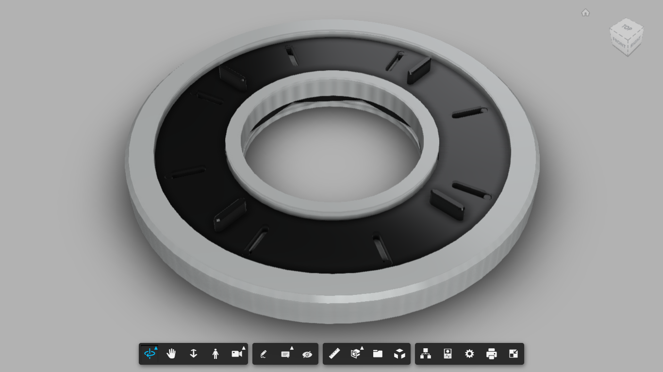
If you don't get what I'm talking about, see this: [https://drive.google.com/file/d/1rTp7cMHPLBTNQeJn548CkIM7rH0K__V0/view?usp=sharing](https://drive.google.com/file/d/1rTp7cMHPLBTNQeJn548CkIM7rH0K__V0/view?usp=sharing)
Fully open
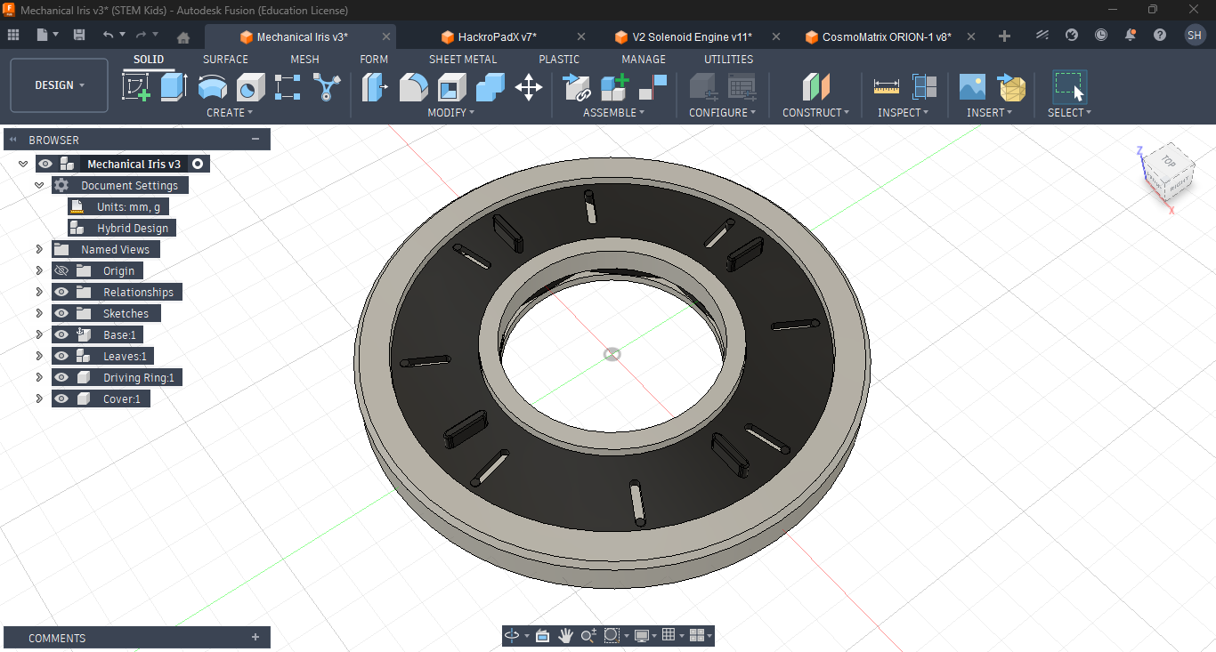
Half-closed
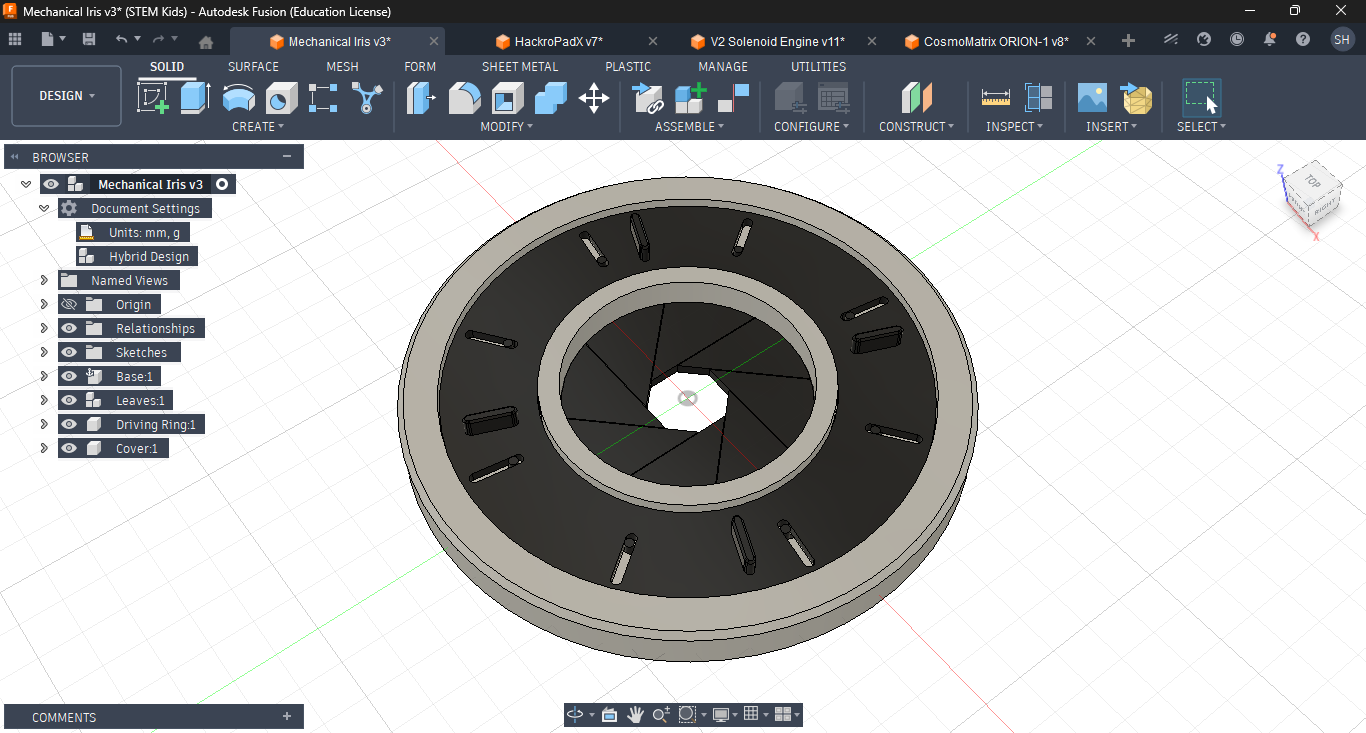
Closed
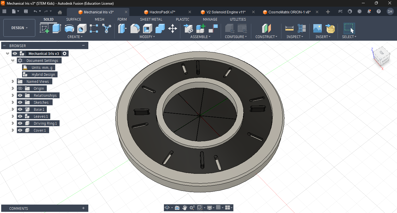
Printing Guide
If you are printing this, you can use the assembled 3mf file and arrange and slice the components in your slicer according to your needs. In case you are using Bambu Lab A1, for convenience you can use the arrangements.3mf in your slicer Bambu Studio. Please note that, in this case the print shall be done in three plates, and for convenience, there is also a sliced file with supports.
Furthermore, whatever slicer you use, please make sure you properly assign the correct color to each slot of the AMS or multicolor system, like this:

If you don't have AMS or any multicolor system, you can rely on using spray paint for the colors which should be done before any assembly.
Assembly Guide
Assembling the project is pretty simple and straightforward. There are files for both the assembled file, which is the default file and the arrangements.3mf suitable for build plate of 256 mm3.
For each component, there are hubs and channels. You can just attach them together by pressing, and simply keep it as it is, if its tight, or you can use super glue. For assembly, it is highly recommended to follow the Autodesk Fusion file thoroughly, and being able to connect the physically printed parts with the components on the .f3d.
Firstly, you will have to attach the Leaves or Blades to the Base, as shown in the image. Make sure that the extrusions are pointing to the top side (the image shown shows the bottom).
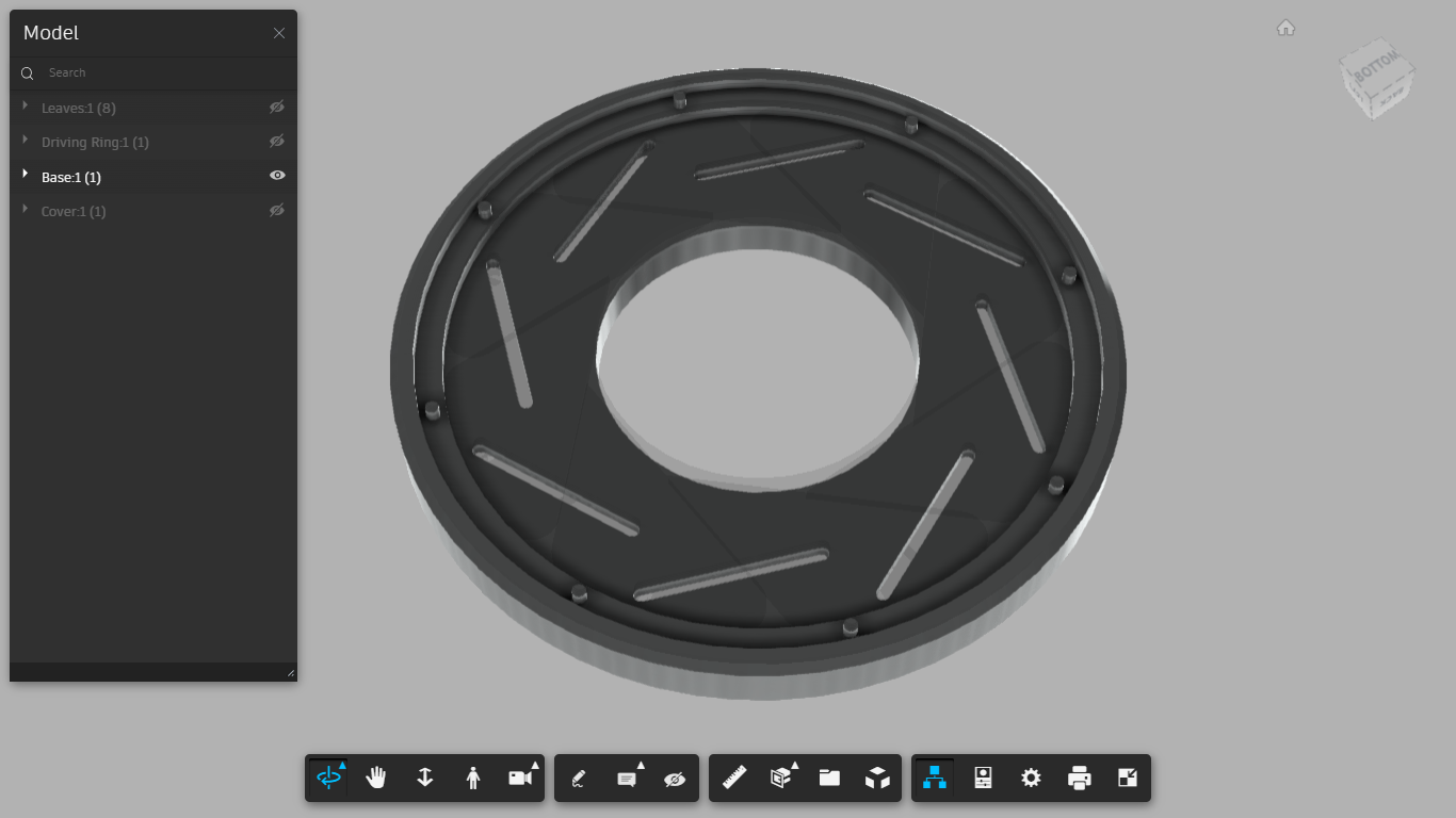
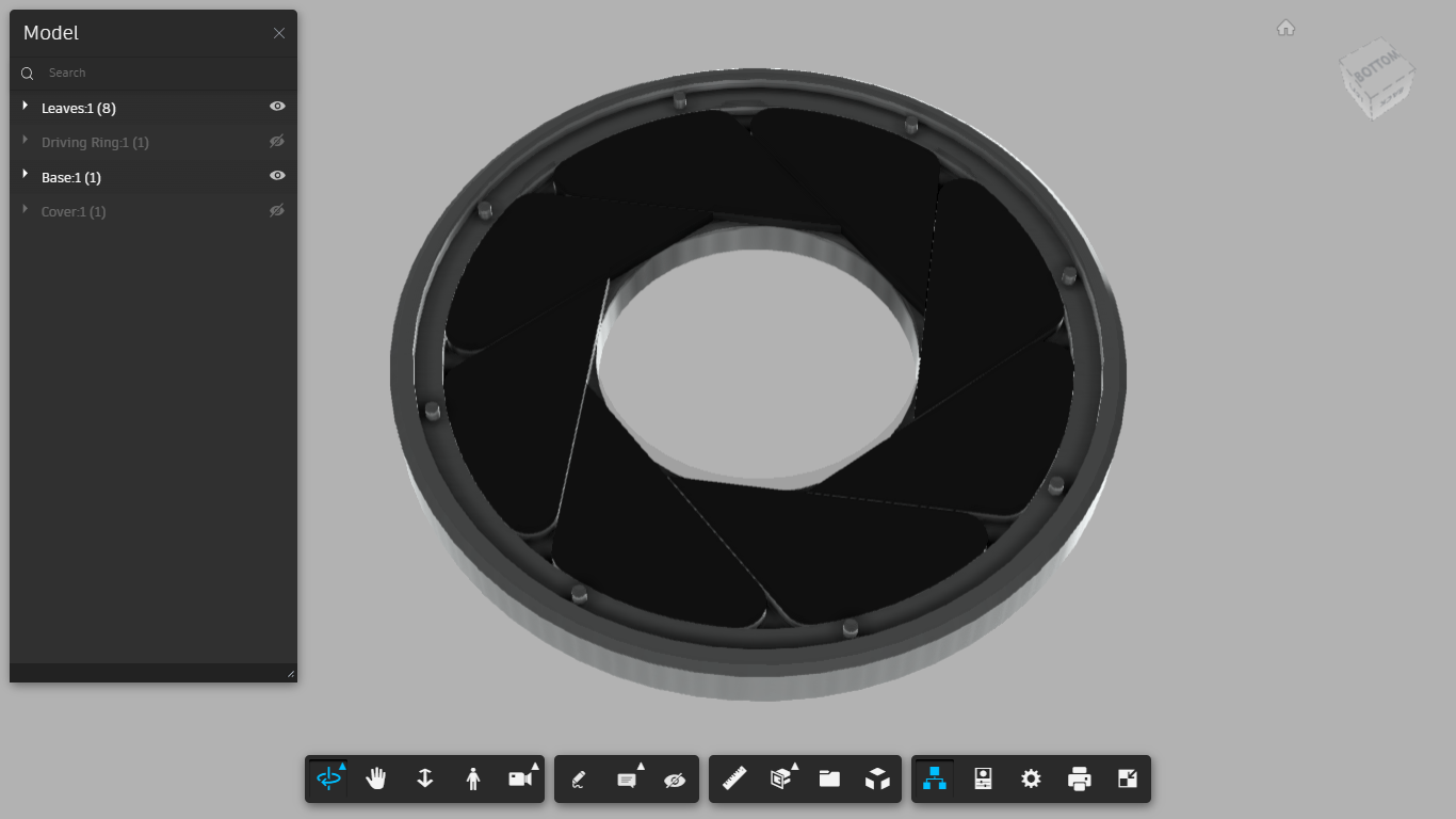
Next, attach the Cover to the bottom. If this is lose, you can use super glue, if needed.
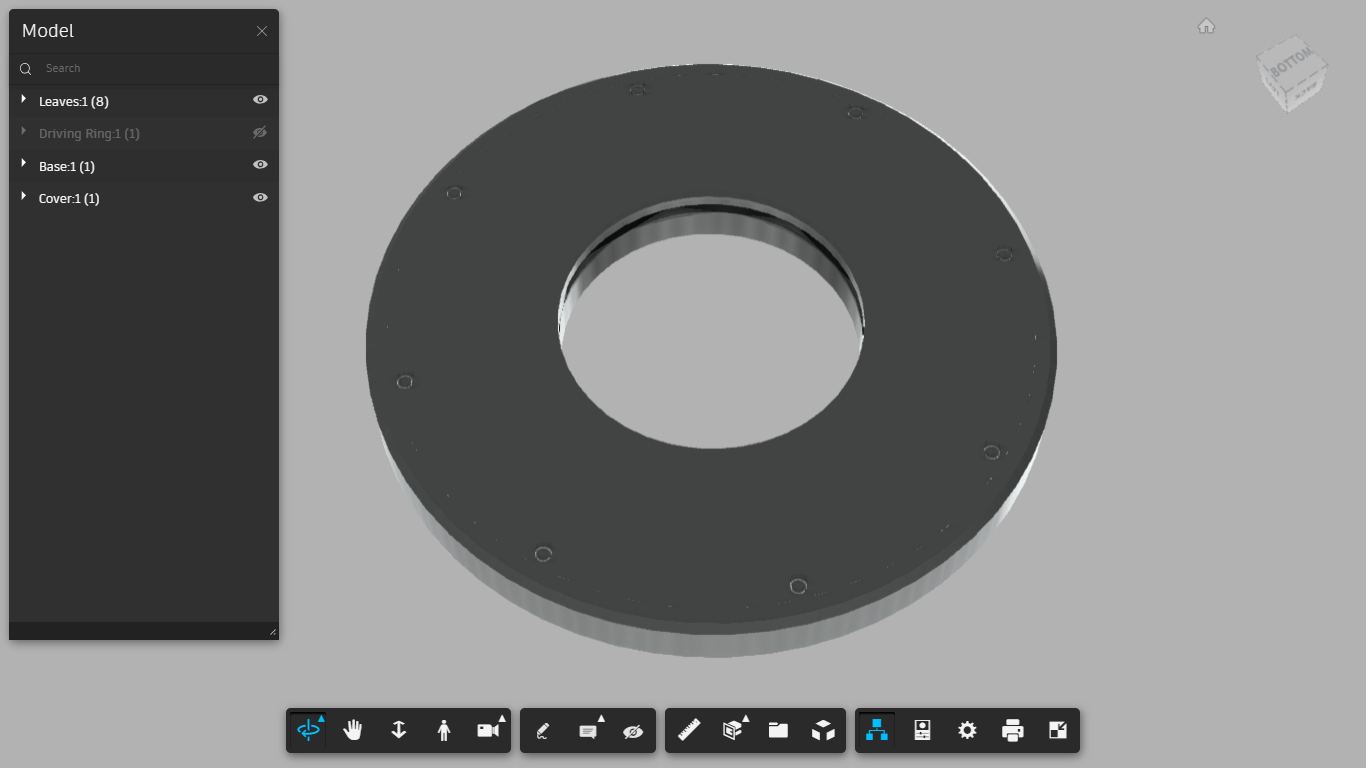
Lastly, place the Driving Ring in the top and make sure it properly aligns with each extrusion of each of the Leaves.
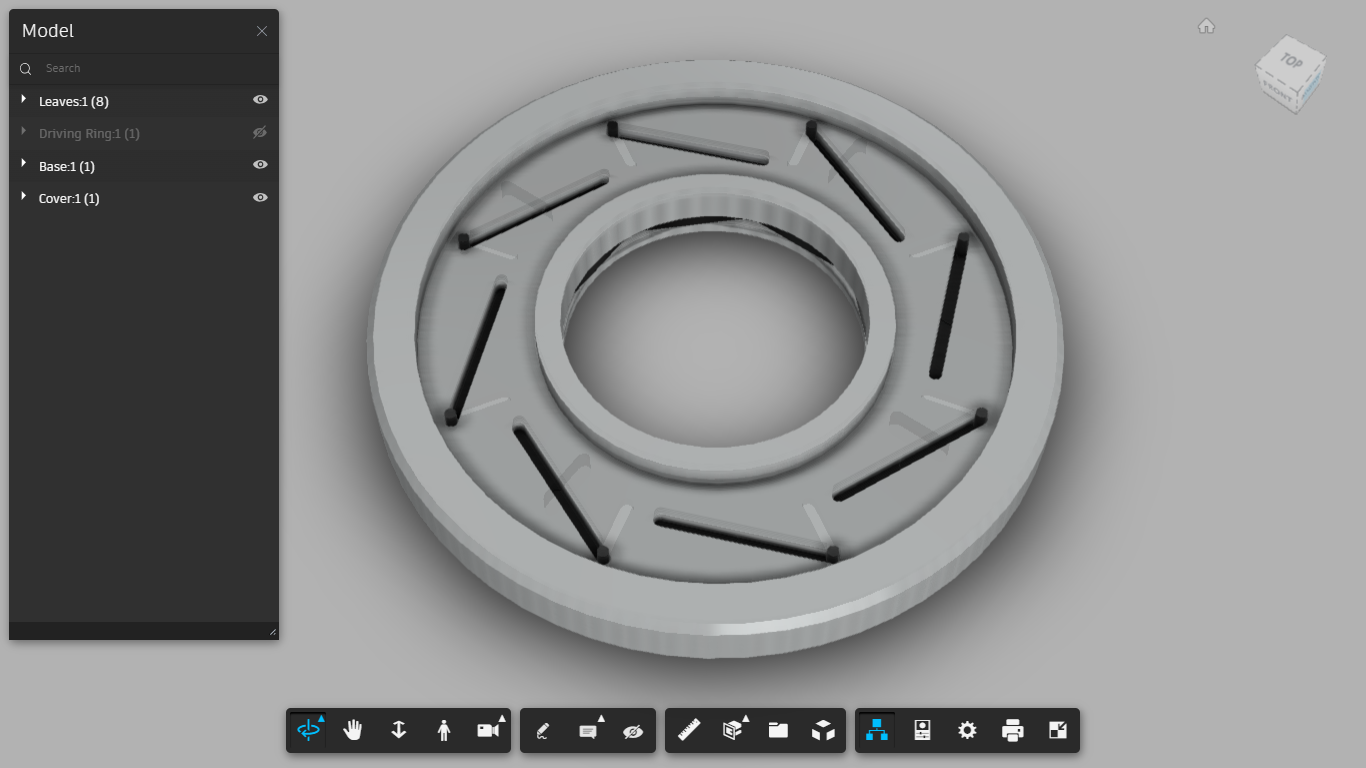
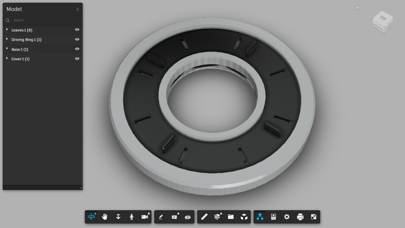
With this, the assembly is done. Now, just rotate the Driving Ring, and you will see it working.

Gostou deste modelo? Crie uma conta grátis para salvar seus favoritos e voltar a eles depois.
Criar conta