Você está no 3DFinder
Buscamos em Thingiverse, MakerWorld e Printables ao mesmo tempo para te dar o melhor de cada uma.
Descrição
Overview
No CAD skills required! Everything is handled via easy-to-use spreadsheets.Smart modularity:
up to 8 user defined modules, where each module can have fully parametric:
up to 4 pillars for PCB mounting
one rectangular hole on the panel
one circular hole on the panel
All-in-one solution:
mounting screws - thread, head diameter
mounting pads - amount, pitches, holes dimensions
honeycomb pattern for cooling - enable/disable, diameter, pitch
Designed in FreeCAD 1.1.0, source files included.
Use the comments section for any questions, issues, or suggestions :)Share your modules, post your prints, create a remix!Before creating a remix by modifying the model itself (rather than just changing the spreadsheets), please refer to the following section: [https://www.printables.com/model/1602115-be-lazy-modular-electronics-enclosure-case-box-par#quality-remix-howto](https://www.printables.com/model/1602115-be-lazy-modular-electronics-enclosure-case-box-par#quality-remix-howto)
Modularity concept
You can configure up to 8 modules. The module meas e.g. mounting area for PCB, hole for connector on the panel, free space with defined dimension etc.
Each module has fixed position (see below), but the dimension of the case is dynamically recalculated.
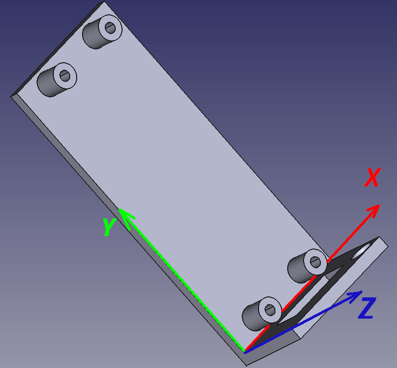
Each module has own coordinate system, which is shifter according to the module number.
Each module is aligned to the panel (enclosure wall) and also to other modules, see below.
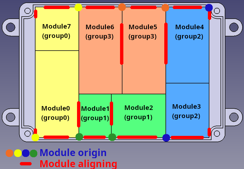
Module configuration concept
Each module has own "space" inside the enclosure. This space is defined by width/length/height. Inside this space, you are allowed to define:
up to 4 pillars by setting dimension (diameter, hole, height) and position (x,y)
one rectangular hole by setting 2 point for rectangular corners
one circular hole by setting center of the circle and diameter
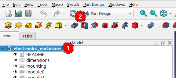
!!! NECESSARY CONFIGURATION OF FREECAD !!!
When you enter any parameter into the spreadsheet, FreeCAD automatically recompute whole model. It can take a time. During setting the parameters, TURN OFF AUTOMATIC RECOMPUTE by right click on the model (see 1 below) and check SKIP RECOMPUTE checkbox.
Click REFRESH button (2) when you are finished with parametrization to recompute the model, be pacient the recompute time can be in minutes.
Model parametrization
Module parametrization
There is a dedicated sheet for each module (Module0 to Module7). Please select the sheet corresponding to your module number.
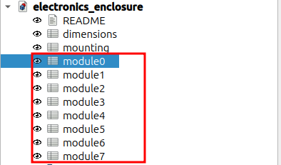
Enable you module - set Enabled=1. OPTIONAL: Set Description and Detailed Information
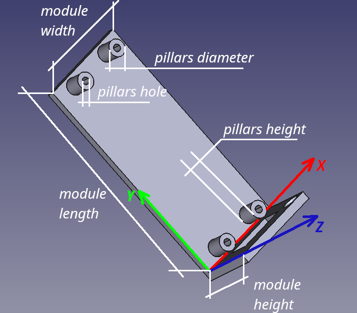
Define module and pillars dimensions.
ATTENTION: There is no spacing defined between the modules. Consider to add "border" of eg. 0.5mm arround your PCB. Of course, change pillars X,Y coordinates accordingly.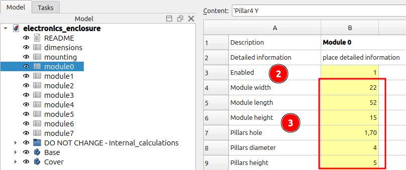
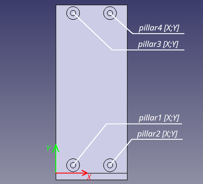
Set X,Y coordinates for pillar1..pillar4. If any pillar will not be used, set X,Y coordinates to 0.
ATTENTION: Each pillar shall be "inside" module area completely, otherwise will not be generated.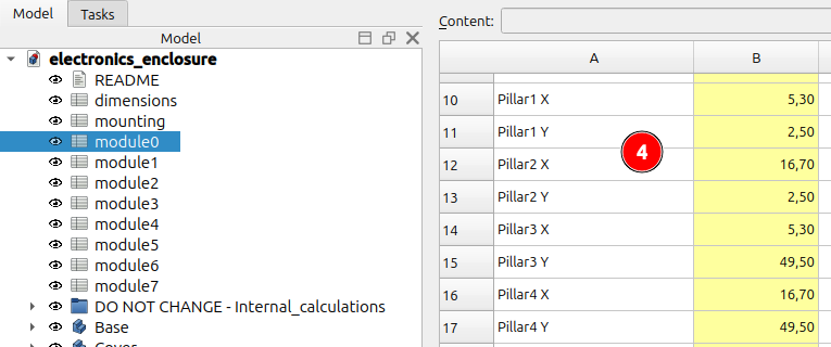
Set X,Z coordinates for rectangular or circular hole on the panel. If any hole will not be used, set X,Z coordinates to 0. When at least one holes is defined, the honeycomb pattern shall be disabled for the module.
NOTE: If no hole is defined and you need to disable honeycomb pattern for the module, set Panel1 fill = 1.
ATTENTION: Holes shall be "inside" module area completely, otherwise will not be generated.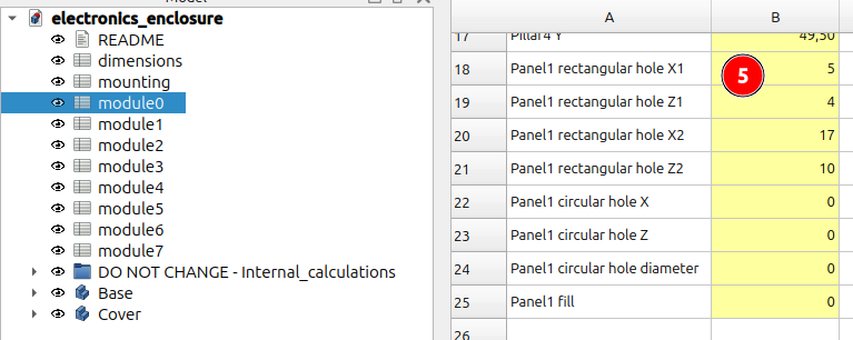
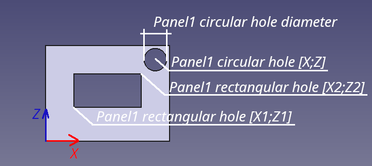
Go to step 1 and define next module :) DO NOT FORGET TO RECOMPUTE MODEL !!!
Box thickness parametrization
Open spreadsheet dimensions in Freecad
Change thickness.


Cover screws parametrization
Open spreadsheet dimensions in Freecad
Change the cover crews thread / hole dimensions.
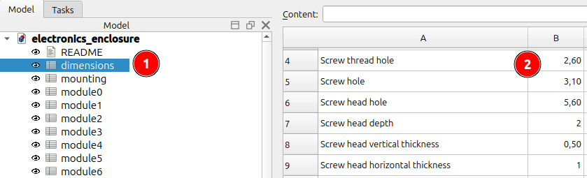
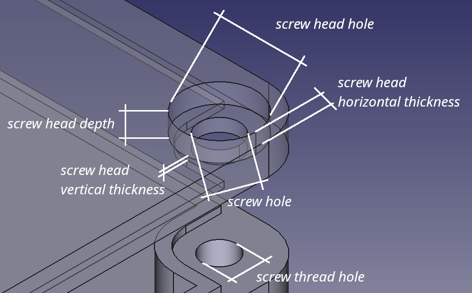
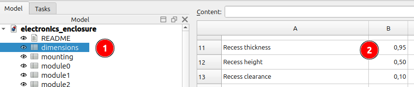
Recess parametrization
Open spreadsheet dimensions in Freecad
Change recess dimensions.

Honeycomb pattern parametrization
Open spreadsheet dimensions in Freecad
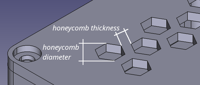
Change honeycomb element diameter or wall thickness between elements
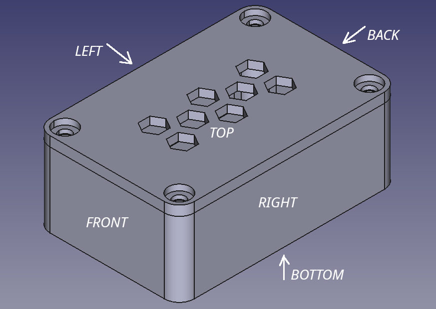
Switch-on (1) or switch-off (0) pattern for concrete faces.
ATTENTION: Do not generate honeycomb pattern on bottom side if you configured pillars for modules !!!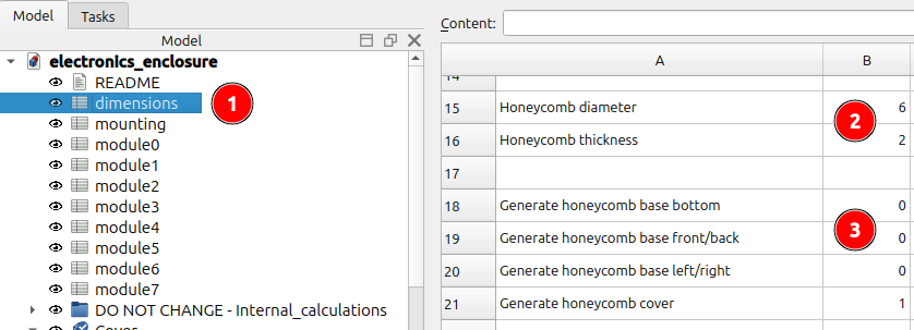
Mounting pads parametrization
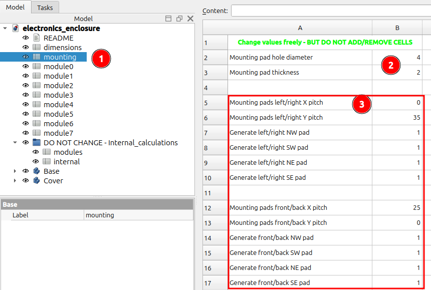
Open spreadsheet mounting in Freecad
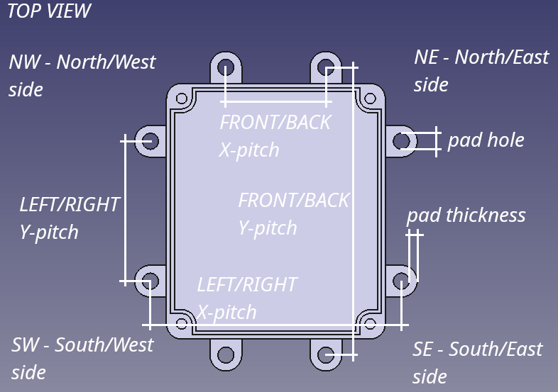
Change mounting pad hole diameter and thickness
Set pitches for mounting pads, switch-on (1) or switch-off (0) mounting pads if needed. Note: If pitch is set to 0, the mounting pad will be generated as close to enclosure as possible.
Export to STL/STEP etc.
Refresh the model if needed, see also TIP in this chapter.
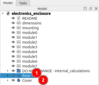
Select Base / Cover part one by one and click File->Export for export to requested format (STL/STEP/...)
Print Settings
The 3MF for simple RaspberryPI Pico 2 enclosure created in OrcaSlicer is included as an example.
Material: PLA
Layer Height: 0.2 mm
Perimeters: 2
Top/Bottom Layers: 2
Infill: Grid 10%
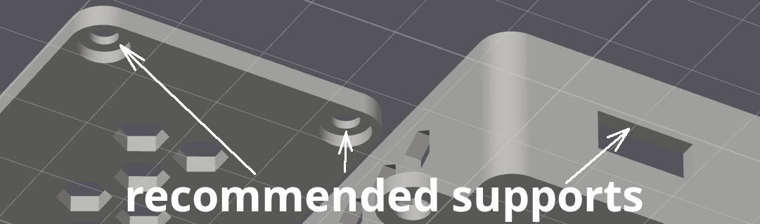
Supports: The honeycomb pattern requires no supports if oriented as shown in be_lazy_pico_standalone.3mf. Supports are recommended for the panel holes in the base and the screw head hole overhangs on the cover.
Bill of Materials (BOM)
The BOM is for example configuration, use your own parts in your project.
1pc ... Raspberry Pi Pico
4pcs ... 1,4x4 BN 13577 screw for thermoplastic
4pcs ... 2,6x6 BN 13577 screw for thermoplastic
Quality remix - HOWTO
INFORMATION: This chapter requires knowledge of FreeCAD.
In some cases, this project may not fully meet your needs, but it can serve as a great starting point. You might need a more complex panel or additional holes for button accessibility. To maintain the modularity of the system, please follow the steps below. If possible, perform complex modeling on module0.
How to modify XY(base) / XZ (panel) area of module:
Create Sketch on selected module's datum plane
(eg. for module0 datum planes are: XY_module0_base / XZ_module0_panel)Perform Pads/Pockets on your Sketches
TIP: Set Panel1 fill = 1 in appropriate spreadsheet to disable honeycomb on panel if necessary.
Updates
2026-03-29
V3 released.
Version scheme changed. Updated atachment of datum planes, sketches.
2026-03-29
V2.1 released.
Honeycomb pattern calculation fixed. Honeycomb is not generated in case of diameter/thickness is too big.
2026-03-27
V2.0 released.
Datum Planes for modules created. SubShapeBinders are no longer used for modeling of modules.
2026-02-18
First release
Disclaimer
The creator is not liable for any damage to your hardware or any unintended results caused by the use of this project, its code, or its documentation. Use at your own risk.
BE LAZY Modular electronics enclosure / case / box - PARAMETRIC

Publicado em 26 de abr de 2026
Gostou deste modelo? Crie uma conta grátis para salvar seus favoritos e voltar a eles depois.
Criar conta