Você está no 3DFinder
Buscamos em Thingiverse, MakerWorld e Printables ao mesmo tempo para te dar o melhor de cada uma.
Descrição
Solderless LED Track Lighting are a modular set of parts that can be incorporated into final electronics projects with minimal to no gluing. The design takes advantage of TPU's flexibility to hold the wires together without the need for soldering or gluing. There are five parts to each LED and a set of wires and covers to connect the track lighting. All parts were printed in TPU except the diffuser and two of the holiday bulbs that were printed in translucent PLA. Each LED base has a spot for a 1/4 Watt resistor to connect the LEDs in parallel.
2/7/25: A draft of the assembly instructions is completed.
Print Instructions:
TPU 95A (DuramiC 3D): Any color can be used.
Resolution: 0.2 mm except Bulbs that were at 0.12 mm.
15% Grid, though most of the parts are so small they are essentially 100% infill.
Sliced with Bambu Studio using the generic TPU settings.
LED files:
LED_base
LED_holder
LED_top
LED_ diffuser (Print with translucent filament)
Bulb files:
Bulb_final: An stl file of the bulb without any slicing information.
Bulb_vase: A 3mf file with slicing details in smooth vase mode and a brim.
Bulb_smooth_fill: A 3mf file with 50% Archimedean Chord fill and a brim.
Bulb_fuzzy_fill: A 3mf file with 15% Gyroid fill and a brim.
TPU bulbs (smooth and fuzzy) were only printed in vase mode. To get the base solid in vase mode, the Bottom Shell Layers were set to 75. The brim was only needed for printing in translucent PLA. The 3mf files have all of the slicing information in them.
Wire files:
Wire_connector: Used to connect wires together that don't have LED holders. The top of the T is where the ground wire is connected, which is the rounded side of the wire. Note the orientation of the T's in the track wire photos.
Straight Wire Holders
Wire_20mm
Wire_40mm
Wire_60mm
Curved Wire Holders
Wire_C40inner
Wire_C40outer
Wire_C80inner
Wire_C80outer
The locking connecting nubs of each wire should be on the top of the wire to snap into the LED holders and wire connectors. Inner means the ground wire is on the inside of the curve; outer is when the ground wire is on the outside of the curve.
Track Cover files:
Wire_cover_20mm
Wire_cover_40mm
Wire_cover_60mm
Wire_cover_C40inner
Wire_cover_C40outer
Wire_cover_C80inner
Wire_cover_C80outer
Non-printed Parts:
5mm LEDs
22 Gauge buss wire (or you can strip insulated 22 Gauge hookup wire).
Sim card ejector (useful for widening holes and pushing wires to one side).
"Coin" battery (to double-check connections).
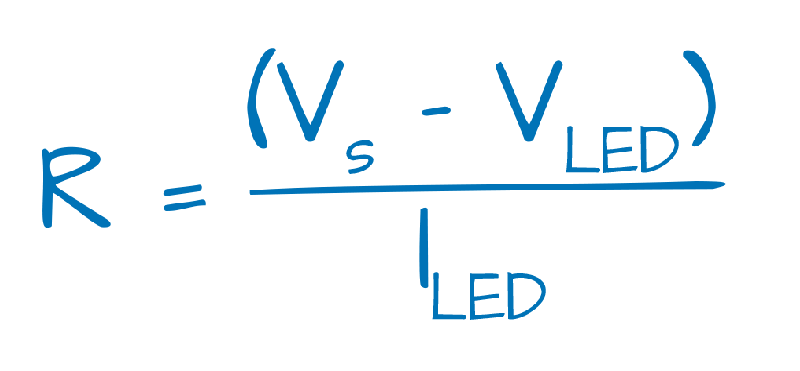
Resistor Tutorial: Ohm's Law (above) can be used to determine the correct resistor to use for each LED. In my example, I was using a Voltage source (Vs) of ~ 4V. All LED's were 20 mA; the yellow and red LEDs were 2V; the blue and green were 3V. Thus, the 1/4 Watt resistors for the different LEDs were:
R = 4 - 3 V / 0.02 A = 1 V/0.02 A = 50 Ω (blue or green)
R = 4 - 2 V / 0.02 A = 2 V/0.02 A = 100 Ω (red or yellow)
I ended up using 47 Ω and 100 Ω resistors.
Assembly: The best order of assembly was: (1) Wire the LEDs and resistors to each LED_holder and insert into base. Double check the connection with some hookup wire and a coin battery. There are two slots to bend the anode and cathode legs of the LED into place. (2) Cut two 22 gauge buss wires (or strip hookup wire of it's insulation) about 150% longer than needed for your setup. (3) Wire the LED furthest away from the power source and then thread the two stripped wires through the wire holder(s) and connectors to the next LED_holder. A Sim Card ejector is a useful tool to initially clear out the holes in the LED_holder as well as to shimmy the wires to the side to make it easier to wire each LED_holder. (4) Repeat until all of the LEDS are wired. Double-check with a coin battery each time you add an LED to the circuit to be sure that the connections are solid. (5) Once the entire wiring is complete, the LED_tops and _diffusers can be added. (6) The different bulbs slip onto the LED tops if your are going for a holiday look versus a project with embedded LEDs. Message me if you want an stl file of the base to build your own bulb.
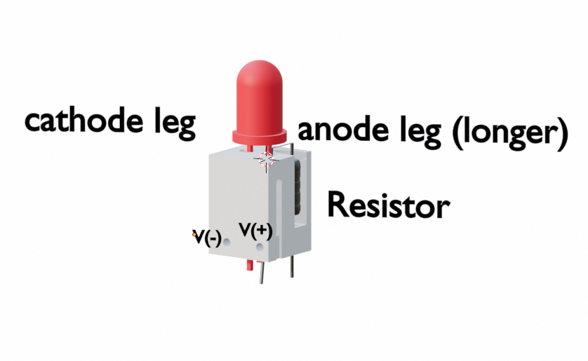
LED wiring: Use a Sim Card ejector to bore out the five holes in the LED_holder. Insert one leg of the resistor into the hole located in it's slot and bend the other leg down through the anode leg hole of the LED. The anode leg hole is at a slight angle such that it doesn't hit the V(+) wire. Gently insert the LED legs into the anode and cathode holes. There are slots on the LED_holder to bend the legs of the LED up into. The lone resistor wire can be bent back into it's channel with no issues since it is very skinny and the TPU base can handle the protrusion. I usually shorten the resistor legs, but leave the LED legs at their manufactured lenghts.
LED Base: Insert the LED-filled holders into the bases such that the cathode leg is on the side of the ground wire. There are tabs in the LED_base to correctly orient the holder in the base. Check each one with some hookup wire and a coin battery to be sure that the connections are solid. Once all LEDs are determined to be functional, start with the LED furthest away from the power source and wire it with two 22 gauge buss wires (or insulation-stripped hookup wires) that are ~ 150% longer needed for your wiring setup just in case. Check with a coin battery that each connection is solid before and after you add the stripped wires to the wire holder(s) and connections. Thread the next LED holder onto the two exposed wires and repeat until you have added all of LEDs to your project.
LED Diffusers: If you are using the diffusers or bulbs, snap on the LED_tops to each LED and insert the diffuser into the slots and turn it 90 degrees clockwise to lock the diffuser into place. The LED_top has tabs in it such that it only snaps to the LED_holder in one orientation.
LED Bulbs: The differnet Bulbs slip over the LED_tops. It's a little challenging to slip the TPU bulbs over the LED_tops as they are a bit flimsy.

Gostou deste modelo? Crie uma conta grátis para salvar seus favoritos e voltar a eles depois.
Criar conta