Você está no 3DFinder
Buscamos em Thingiverse, MakerWorld e Printables ao mesmo tempo para te dar o melhor de cada uma.
Descrição
This mod adds 3 push buttons to my User port enclosure that you can connect to the internal button header of the C64U / Elite II
WARNING: The tolerances on this design are extremely tight, so depending on your printer calibration, you may run into fitment issues. I was able to test it with my older user port board (the green one), and it worked without any issues. Added a 1mm higher version (see changelog)
Changelog
05/04/26
- Added a 1mm higher version for both cap models to provide more clearance for the top of the flatcable connector.
03/02/26
- Fixed: The depth of the two blocks inside the cap was different than that of the original cap.
01/02/26
- Fixed: Forgot to add a small cavity on the back of the regular cap
- Added an extra set of buttons for use with 4.3 mm high buttons (moved stem closer towards button)
Info
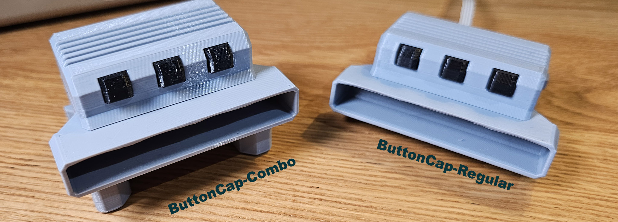
There are two different cap versions included in the files: one for the raised enclosure and one for the regular low-profile enclosure. They are interchangeable, but there is a slight difference in the design at the back of each cap.
Regular:[https://www.printables.com/model/1553507-c64-ultimate-elite-2-tape-to-user-port-adapter-202](https://www.printables.com/model/1553507-c64-ultimate-elite-2-tape-to-user-port-adapter-202)
Combo:[https://www.printables.com/model/1567413-c64-ultimate-elite-2-user-port-combo-adapter-2026](https://www.printables.com/model/1567413-c64-ultimate-elite-2-user-port-combo-adapter-2026)
Print Settings:
Nozzle: | 0.4 mm |
Layer height: | 0.2 mm |
Perimeters: | 3 |
Infill: | 15% |
Support: | none |
Parts:
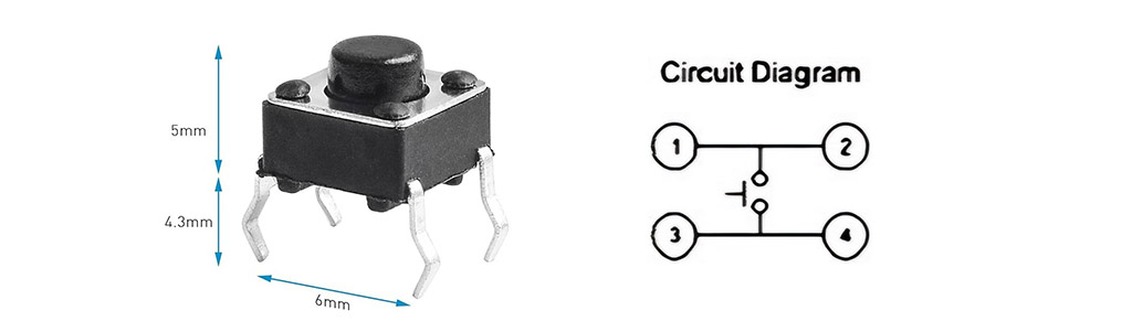
Tact switches | The design uses 6x6x5 mm Tact-switches. I will add some additional buttons for 4.3mm high switches. |
Flatcable | 4 wires (I used a piece of flat cable, you may be able to find something with the connector already attached). |
Female header | 4 pin |
Assembly Instructions:
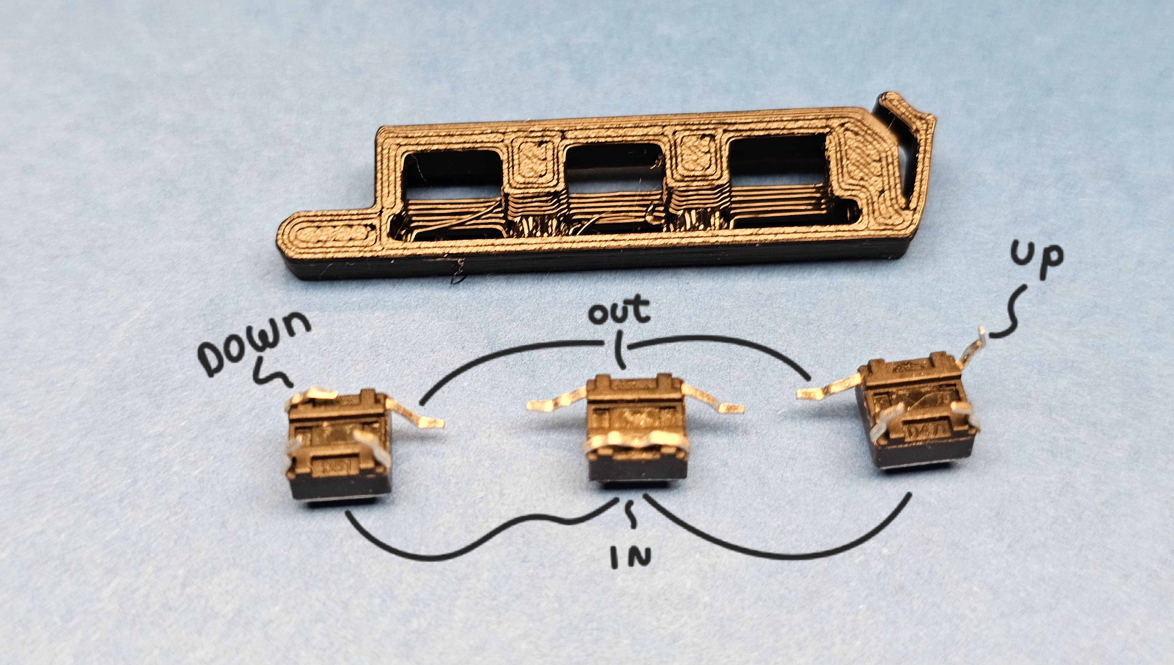
Fold the pins as shown in the image above.
(*The legs on the middle one are folded a bit too flat; simply bend them slightly inward, as shown on the left and right.)
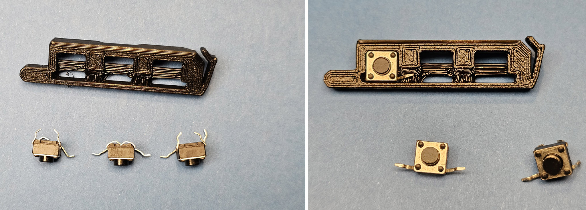
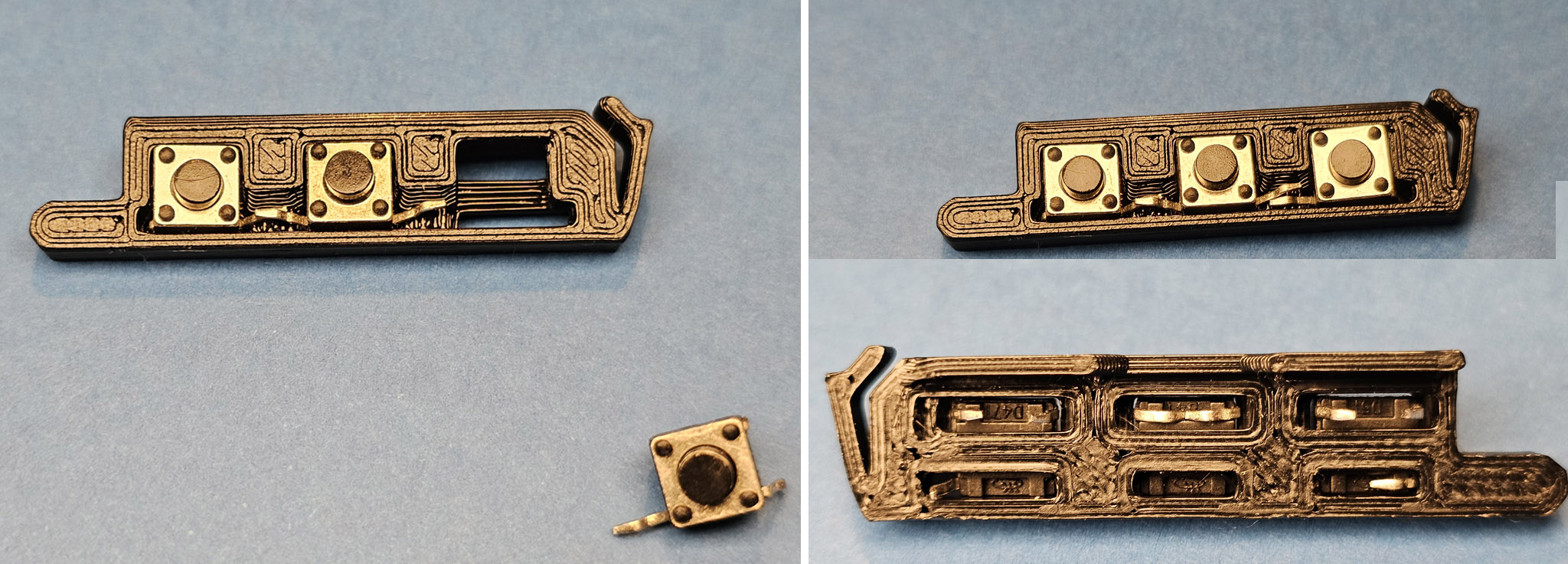
Insert the switches and make sure you push them firmly flat against the bottom.

Solder the pins on the front together.
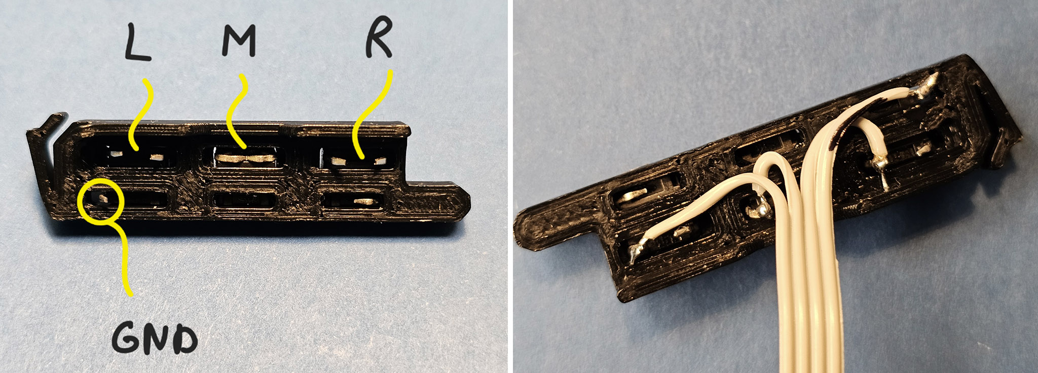
Solder the pins on the back from left to right (GND, L, M, R). This order corresponds to the connector on the motherboard (from bottom to top).

Solder the connector to the cable (it helps if you mark the GND wire)

Let's put everything together

Insert the buttons, then place the block with the pin into the cavity on the left.

Gently push the block downward into the cavity.
It can help to use a flat screwdriver to push the switches slightly backward so they can slide past the small push block.Once the block sits flush with the bottom, use a screwdriver to push it a little further to the left.
The small lip should click into place.

Before adding the cap, make sure that the wire is bent as flus as possible towards the connector.
Remove the block

If you need to remove the block, push the lock pin back and use a screwdriver to lift it up, as shown above.
Button Cap for User port enclosure

Publicado em 5 de abr de 2026
Gostou deste modelo? Crie uma conta grátis para salvar seus favoritos e voltar a eles depois.
Criar conta