Você está no 3DFinder
Buscamos em Thingiverse, MakerWorld e Printables ao mesmo tempo para te dar o melhor de cada uma.
Descrição
SUMMARY
- It’s 13 cm tall by 6 cm wide with a depth of 1 mm. It has 2 eyes and some style on the top and bottom.
- Everyone got a ghost clip and we were instructed to design a sketch on paper of how the final
- SolidWorks sketch would look with our partners (@asterzinno_3775778 @FestiveAxis5_3775769). After making our identical and best idea of how the ghost clip would look like in the program we completed a ghost clip instruction guild to follow (see “GHOST CLIP TUTORIAL”), that way we could complete the sketch on SolidWorks with little issues and identical sketches. We were then approved after some simple adjustments to get on SolidWorks and make the sketch. We made adjustments as we went when something was wrong and once complete we checked our work. We extruded our sketches and exported them as a printable 3d model and lastly our work was checked against the original ghost clip for errors.
- Link to partners’ reports. Aster, Joshua.
ESSENTIAL QUESTION
- With a partner (or partners), can you will recreate your ghost clip using SolidWorks? You and your partner(s) MUST have identical files that you create by collaborating on each step, one at a time.
GHOST CLIP TUTORIAL
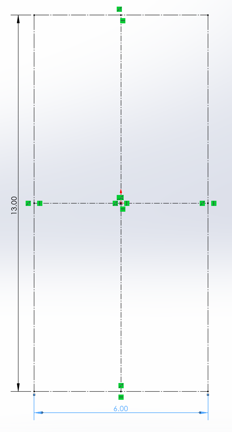
BOUNDING BOX
- a) Use the center rectangle tool (
 ) with construction lines from the midpoints centered on the origin to create the bounding box.
 - b) Mark the rectangle for construction.
- c) Use smart dimensions (
 ) to set the dimensions to 6 cm horizontal by 13 cm vertical.
SMILE
- a) Use the circle tool (
 ) to make a circle centered on the vertical construction line in the bottom half
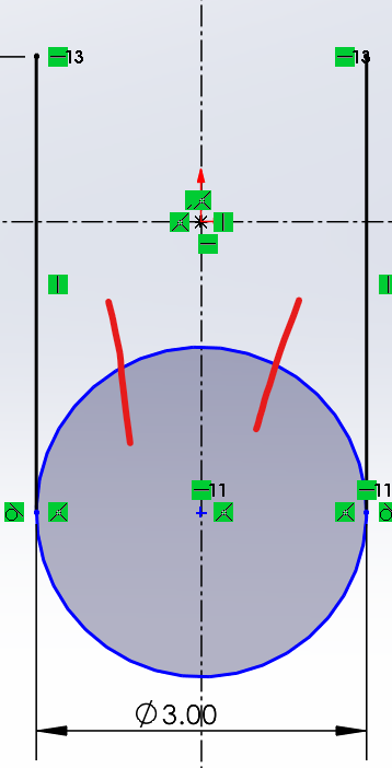
- of the bounding box but not touching the bottom.
- b) Use the smart dimension tool (
 ) to set the diameter of the circle to 3 cm.
 - c) Use the line tool (
 ) to draw a vertical (
 ) line tangent (
 ) to the circle going about a third of the way up the bounding box, then do the same for the other side.
 - d) Select the top endpoints of the lines created in step c and give them the horizontal relation (
 ) to align the endpoints at the same height.
 - e) Use a smart dimension (
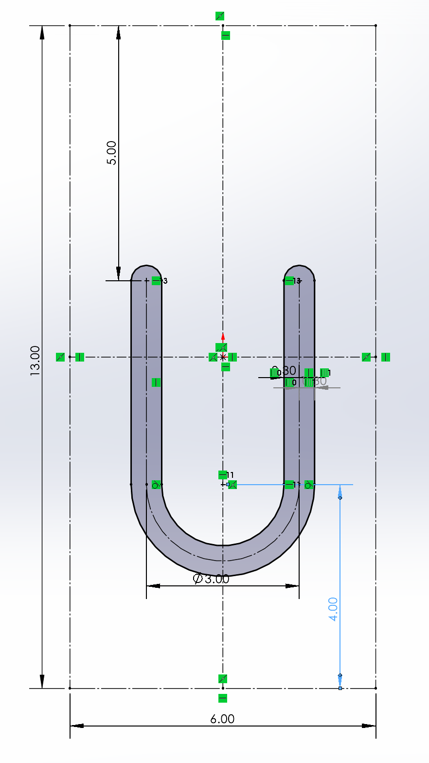
 ) to set a distance of 5 cm from the top of one of the vertical lines from step c to the top edge of the bounding box.
 - f) Use the power trim entities tool (
 ) to remove the top half of the circle in between the vertical (
 ) lines, leaving the vertical construction line intact.

- g) Mark these two lines and arc for construction.
- h) Use the offset entities tool (
 ) on the arc and vertical lines to create a bi-directional 0.3 cm offset with arc cap ends.
 - i) Use the smart dimension tool (
 ) to set the distance from the center of the arc to the bottom of the bounding box to 4 cm.
BOTTOM SEMI-CIRCLES

- a) Use the perimeter circle tool (
 ) to create a circle starting 1 cm above the bottom left corner of the bounding box with a second
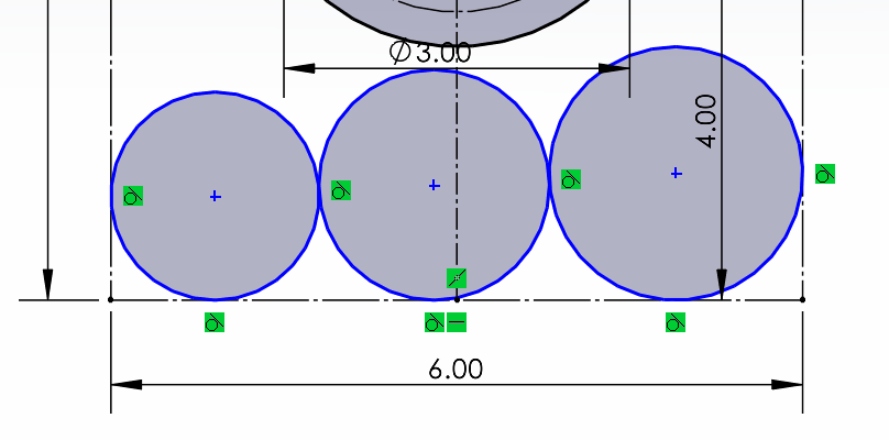
- b) point 2 cm to the right and a radius of 1 cm and with the 3rd point touching the bottom edge of the bounding box.
- c) Repeat step a twice but with the first point of each circle being the right edge of the previous circle, and with the final circle being tangent to the right edge of the bounding box.
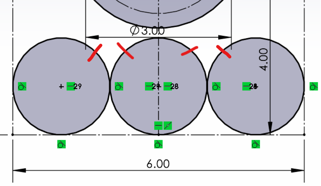
- d) Use the horizontal relation (
 ) to set the center points of each circle from steps a and b to horizontal to line them up at the same height.
 - e) Use the power trim entities tool (
 ) to remove the top half of each circle in between the horizontal lines, leaving the vertical construction line intact.
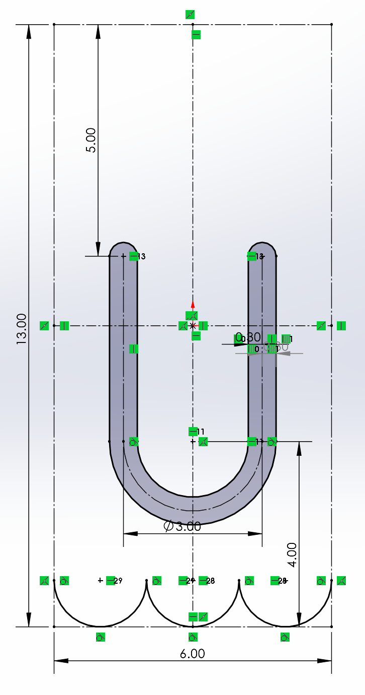
TOP SPIKES
- a) Use the center line tool (
 ) set to construction to create a 1 cm long horizontal (
 ) line starting 1 cm below the top of the bounding box.
 - b) Repeat step a five more times, creating horizontal (
 ) lines that start from the end of the previous line, until you reach the end of the box.
 - c) Use equal relations (
 ) to make the construction lines made in steps a and b equal.
 - d) Use the line tool (
 ), create a diagonal line from the start point of the first construction line to the top of the bounding box, ending directly above the midpoint of the construction line.
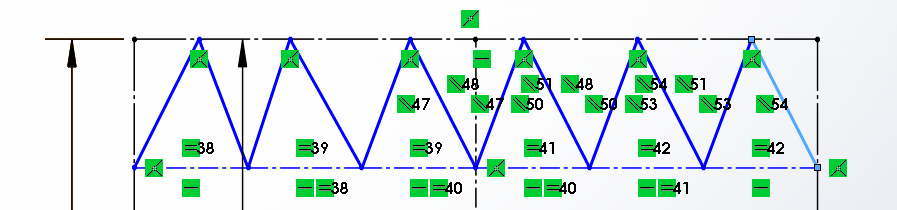
- e) Use the line tool (
 ), create a diagonal line from the end of the previous diagonal line to the end of the current construction line.
 - f) Repeat steps d and e until you reach the end of the bounding box.
- g) Use the equal relation (
 ) to make the diagonal lines made in steps d-f equal.
 - h) Use the smart dimension (
 ) tool to set the length of the diagonal line from step e to 1 cm.
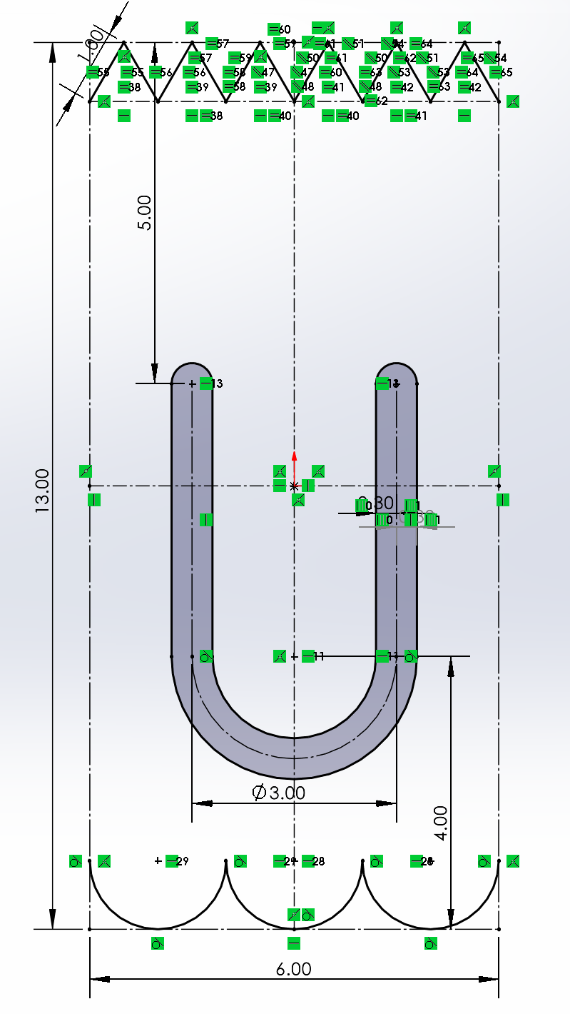
EYES
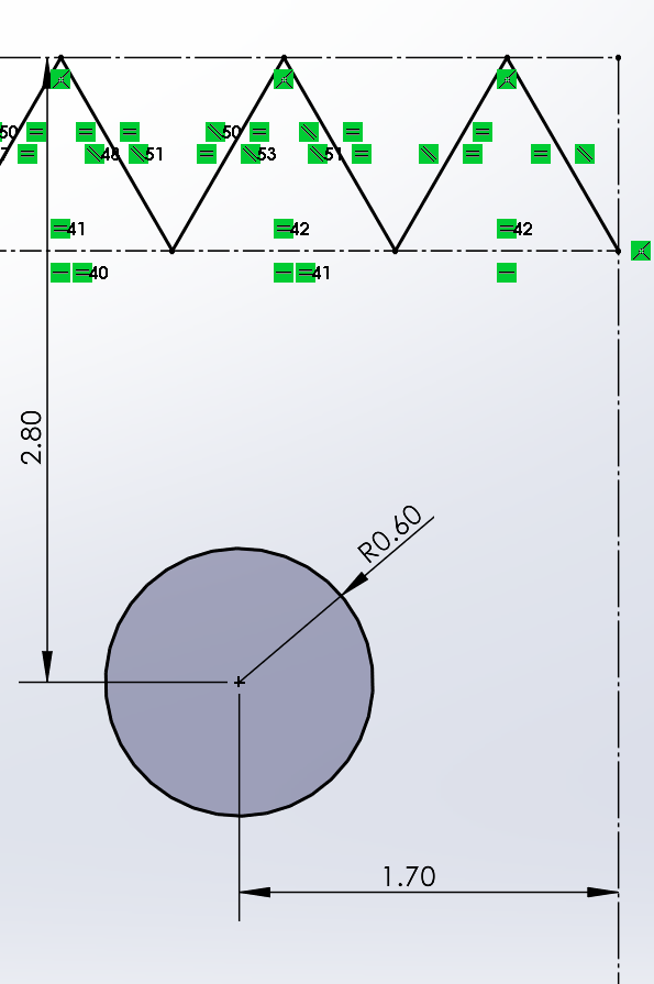
- a) Use the circle tool (
 ) to create a circle in the top right quadrant of the bounding box.
 - b) Use the smart dimension tool (
 ) set the radius of the circle in step a to 0.6 cm.
 - c) Use the smart dimension tool (
 ) to set the distance between the center of the circle and the top edge of the bounding box to 2.8 cm.
 - d) Use the smart dimension tool (
 ) to set the distance between the center of the circle and the right edge of the bounding box to 1.7 cm.
 - e) Use the mirror tool (
 ) to mirror the circle along the vertical construction line going through the middle of the bounding box.

CLOSING THE SHAPE
- a) Use the line tool (
 ) to create a vertical (
 ) line starting from the left most point of the spikes, to the left most point of the bottom semi circles.
 - b) Repeat step a for the right side.
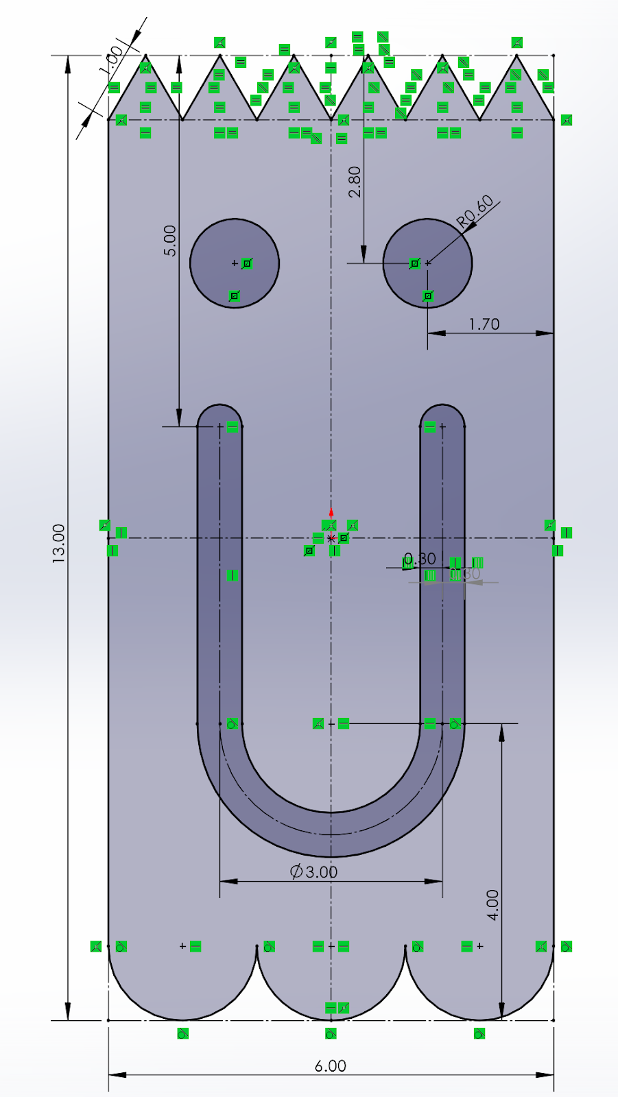
EXTRUDING THE SKETCH
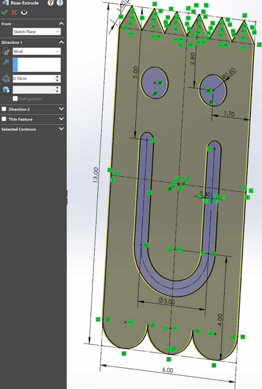
- a) Go to the features tab and use the extrude boss/base tool (
 ) to extrude the sketch 1 mm/0.1 cm like shown in the screenshot. Then you can do what ever you want like engrave text like we did.
SKETCH ADJUSTMENTS AND DESIGN CHOICES
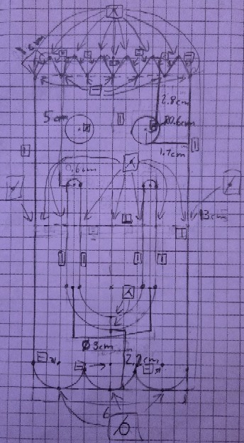
Paper sketch design choices
- We tried to use as many relations as possible because smart dimensions are finicky and are easy to mess up. By having more relations and less smart dimensions we were able to simplify and fully define the sketch more efficiently.
- We had to change the sketch to reflect our changes we made in the design process so this is before making the tutorial:
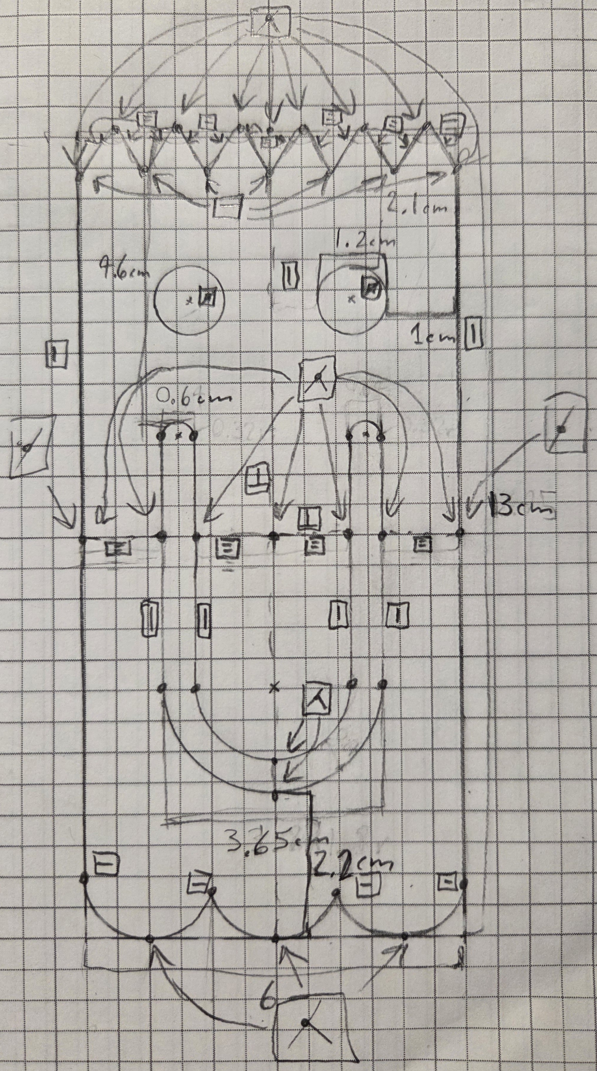
- And after doing the SolidWorks:
Necessary tutorial adjustments
- We changed the offset to be after the diameter of the half circle was set, so that offset overlap was impossible, fixing possible confusing troubleshooting.
- We rephrased how the semicircles were repeated to make more sense.
- The bounding boxes middle horizontal construction line originally replaced a set of 4 similar construction lines but we realized that they were not necessary.
Necessary logistics adjustments
| Screenshots | Logistics adjustments |
 | We adjusted the tutorial to say to make the bounding box marked for construction as you make it instead of what we had before, which was after. |
 | We replaced “Center point circle tool” to “Circle tool.” |
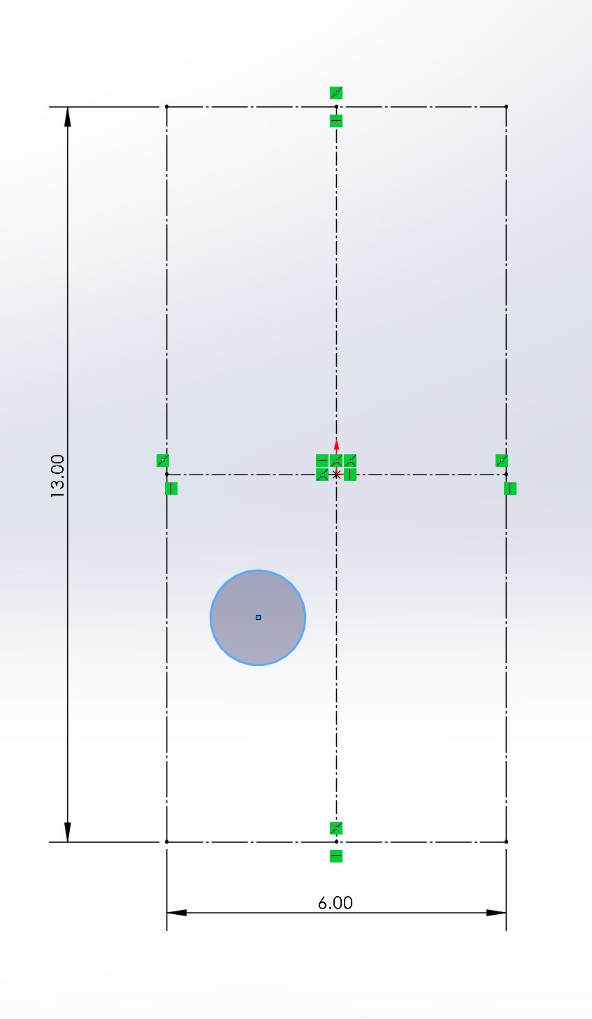 | We made the circle coincident to the middle of the vertical construction line by default showing the yellow relation while creating it instead of setting it later. |
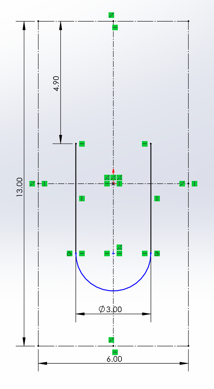 | We changed the tutorial to not erase the middle vertical construction line by specifically telling people to avoid it and use trim 2 times. This sets the president for the bottom semi-circles as well to avoid a similar problem. |
 | We changed the original perimeter circles to make the circles tangent instead of the second point. Also making sure the last point is tangent to the right side. Then instead of using the top points as horizontal we changed it to use the center of the circles instead. We removed the smart dimension step as well. |
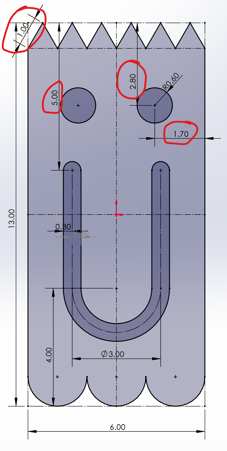 | The red circles circle the smart dimensions that were changed in the comparison step with the original printed ghost clip. |

3
Curtidas
5
Downloads
1
Impressões
Categoria
Office
Licença
Creative Commons — Attribution — Noncommercial
Arquivos (1)
Lastua_L_STF.3mf
32.7 KB
Gostou deste modelo? Crie uma conta grátis para salvar seus favoritos e voltar a eles depois.
Criar conta