Você está no 3DFinder
Buscamos em Thingiverse, MakerWorld e Printables ao mesmo tempo para te dar o melhor de cada uma.
Descrição
While the 🥰 CORE One is an excellent printer with a well-designed stock system, this modification offers mechanical improvements for enthusiasts seeking enhanced precision and reliability. The Pins Mod inspired by the Voron community upgrades the XY gantry system by replacing the standard M3 bolts used for idler mounting with 3mm steel axles (pins). |
Key Improvements
Eliminated Idler Play on the M3 bolts
Smoother Operation that reduces potential vibration and mechanical noise
Toothed Idler Integration: Optimizes belt engagement using purpose-built toothed idlers (optional)
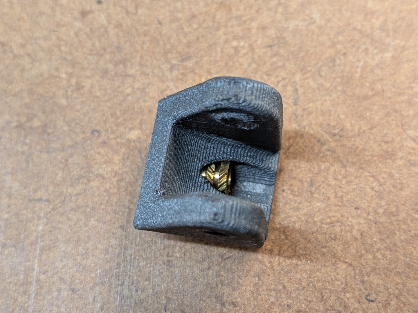
Improved Reliability for the the Belt Tensioner mechanism by using a heat set insert (optional)

Personally, I would never build a CORE One without this modification, so I can only encourage you to consider going this route. I'll do my best to describe every detail of what you need to do and help you understand the reasoning behind each step. This will be somewhat lengthy, but it will help you get it done successfully.
That being said, here's a time estimate: Plan around 90 minutes for reading, understanding, and building. You'll be rewarded with a beautifully play-free gantry system at virtually no extra cost - it's truly worth the effort 😎. |
CORE One L user? The XY Motor Mounts for the Core One L require slightly different parts. Find these adapted mounts in the companion model: Core One L Pins Mod. All other parts and instructions are exactly the same, just print those two replacement parts. |
Printed Parts
XY Motor Mounts |
XY Carriage
|
Belt Tensioner Pulley
|
Press-In Tools
|
Assembly
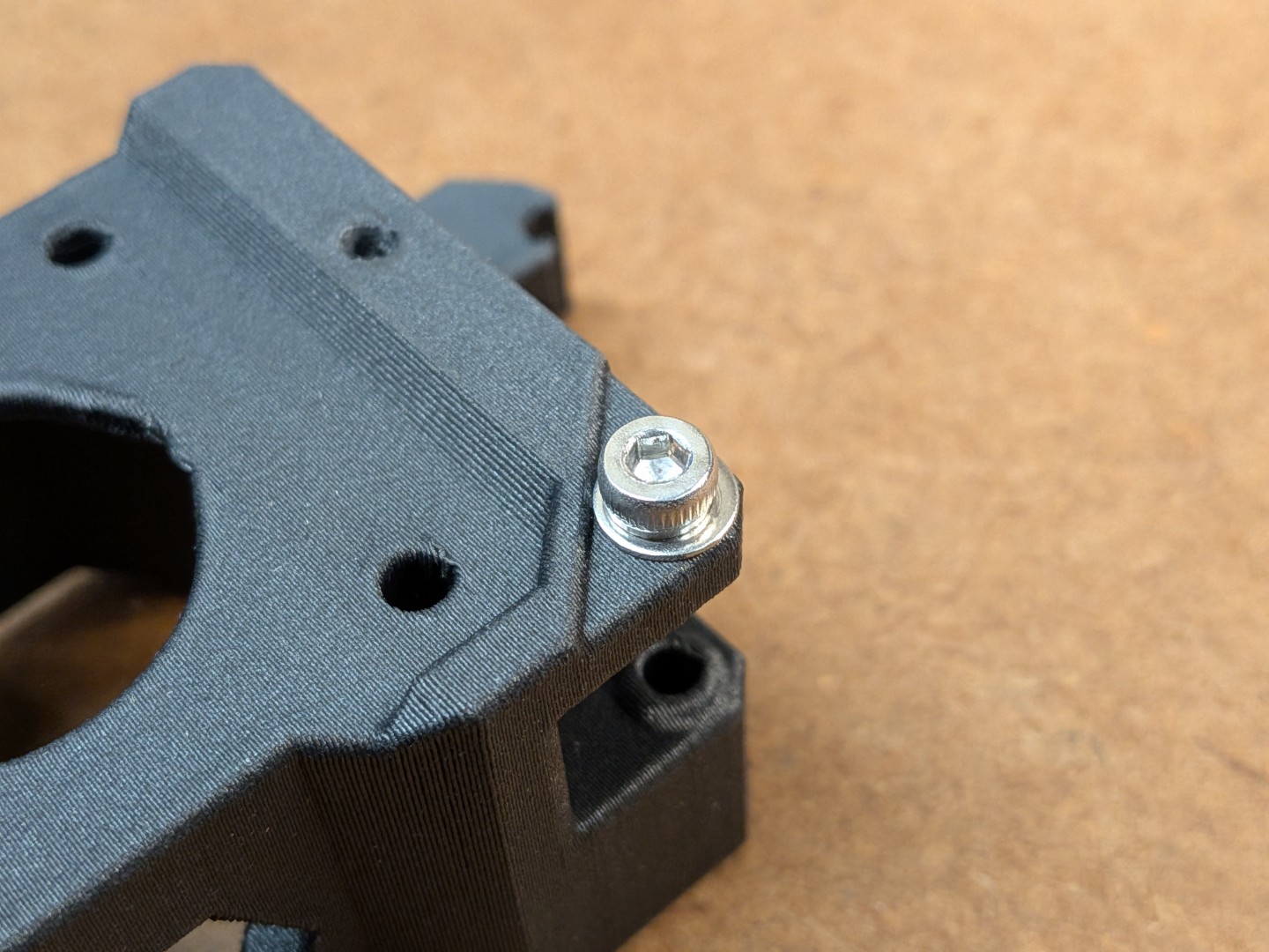
Printed-Parts Preparation
 |  |  |  |
 |  |  |  |
Hole Preparation
Make sure you prepare all holes as described. Otherwise you will risk to split the parts if there is too much stress especially along the layers. |
Heat Set Insert Installation
|
Details: Pins placement and drill-open option
Motor Mount:
 | 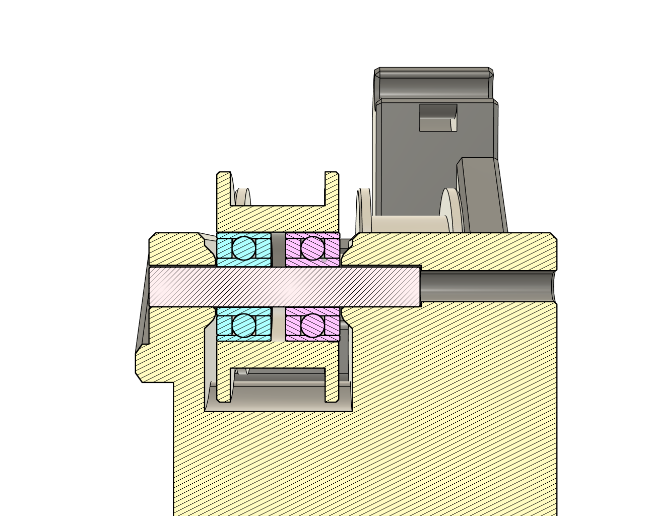 |  |
The pins in the Motor Mount parts do not go all the way through. Follow the instructions and drill out the “inner” hole from the inside using a longer bolt. Alternatively, use a 2.5mm drill to open the 1mm endstop and you can then use the M3 bolt technique from the outside of the part.
The idea of this design decision with the tiny 1mm end-stop:
Have an end-stop for the pin
Make it clear from what side the pin should be inserted.
After having assembled the parts, I think the decision to have this 1mm endstop just made the process more complicated with no real benefit. But I did not want to change the design but get the project finished. And you do have the option to just drill open the last 1mm as described with no downside. |
XY Carriage:
 |  |
Belt Tensioner:
 |
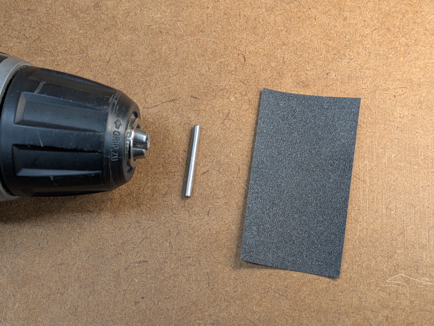
Pin Preparation
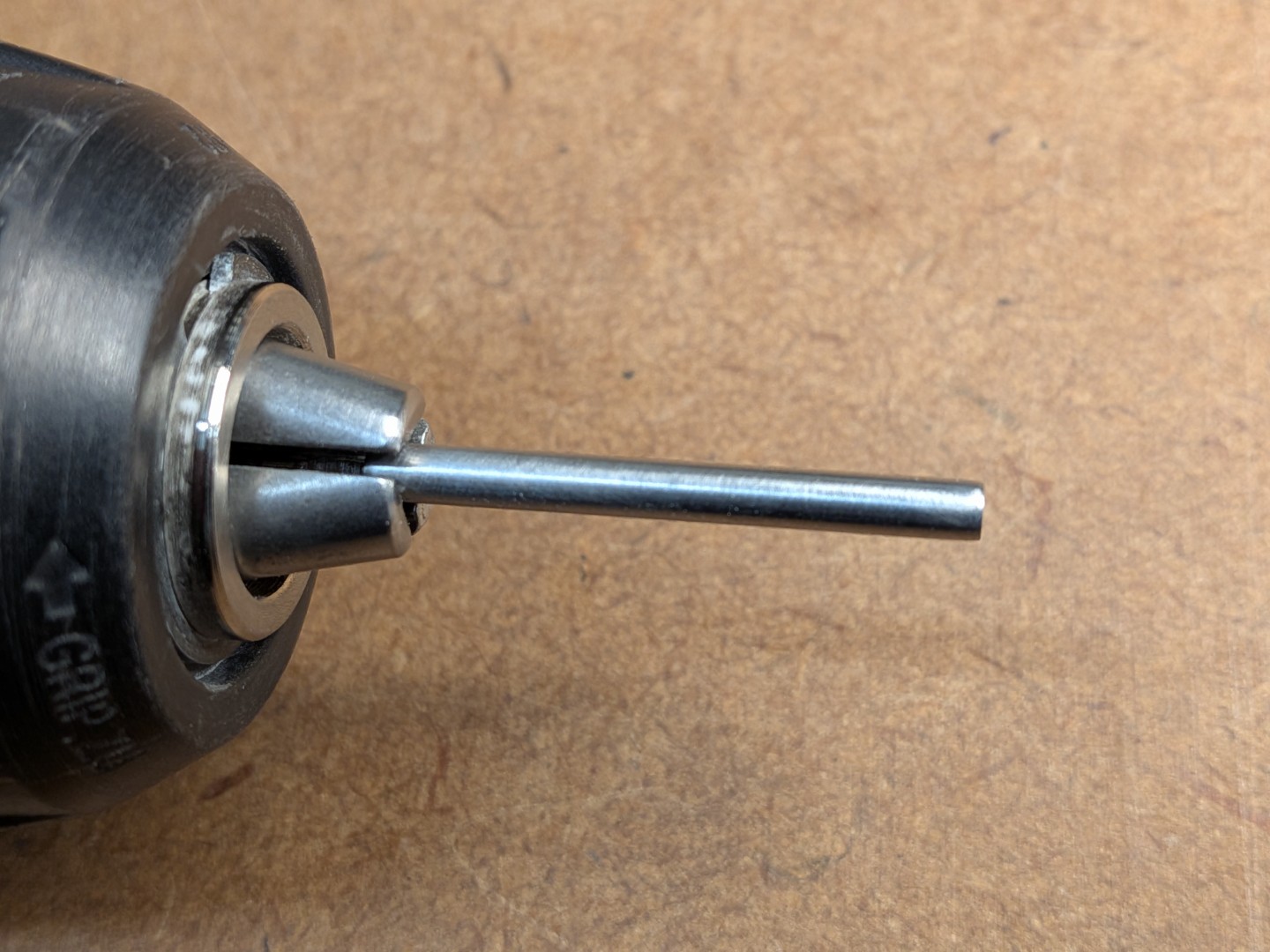
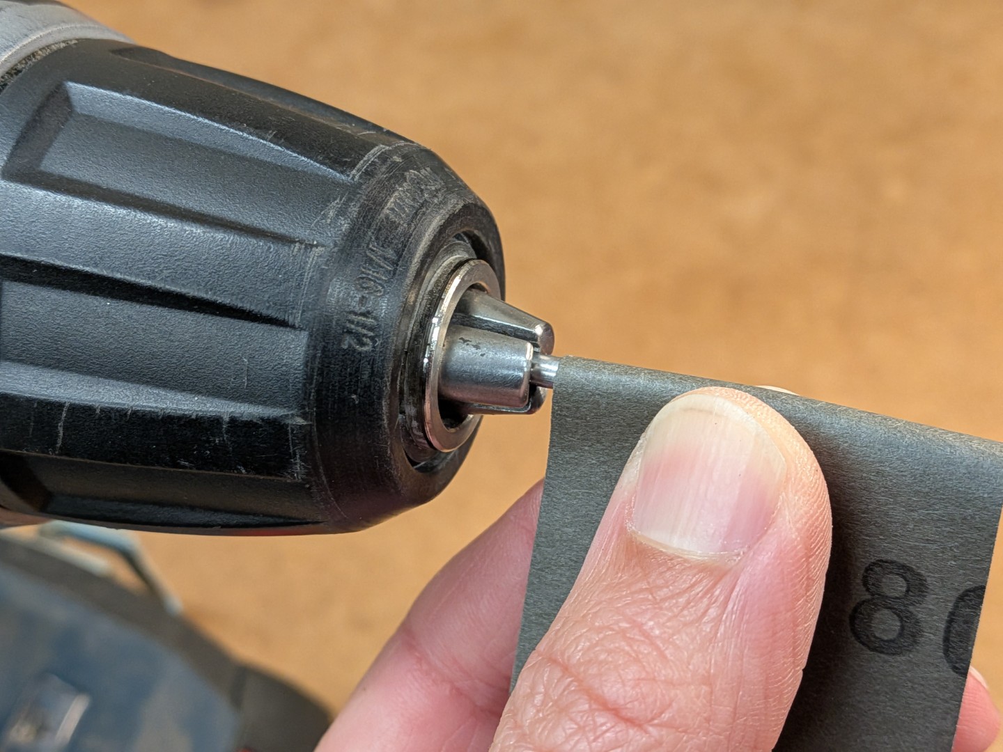
Standard 3mm steel pins may require sizing to achieve proper bearing tolerance. This process ensures optimal fit without bearing damage.
⚠ Critical Safety Note: Never force pins through bearings - any stress on the inner bearing race can cause permanent damage |
 |  |  |  |
Initial Preparation
|
Sizing Process (if pins are oversized)
|
Quality Check: Final pins should insert smoothly into bearings with no resistance or binding |
Idler Assembly
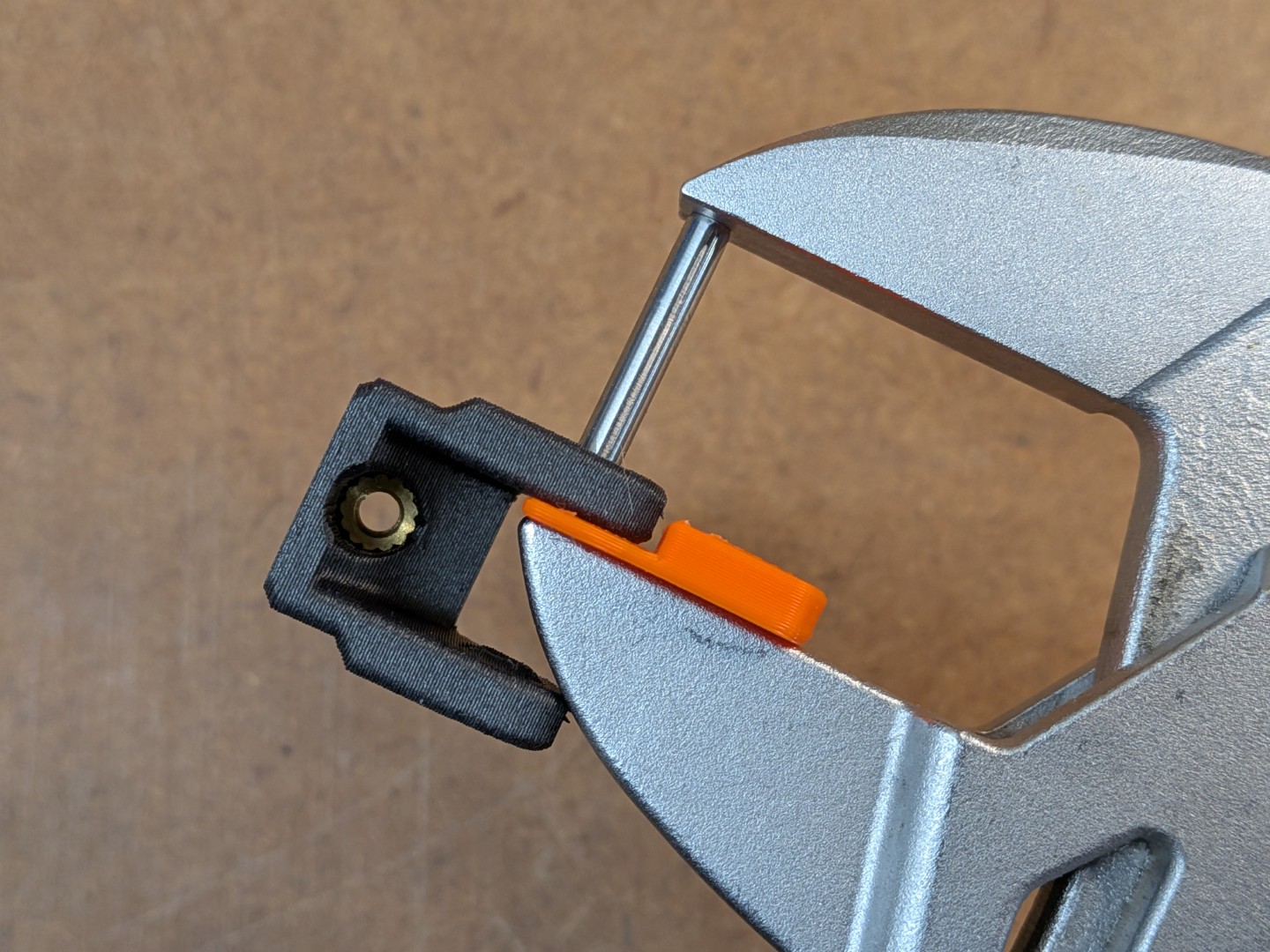
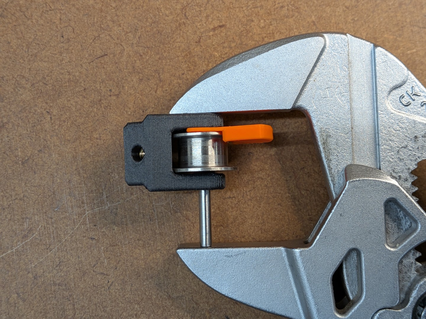
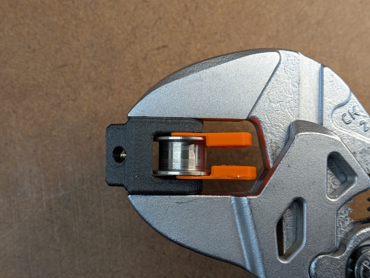
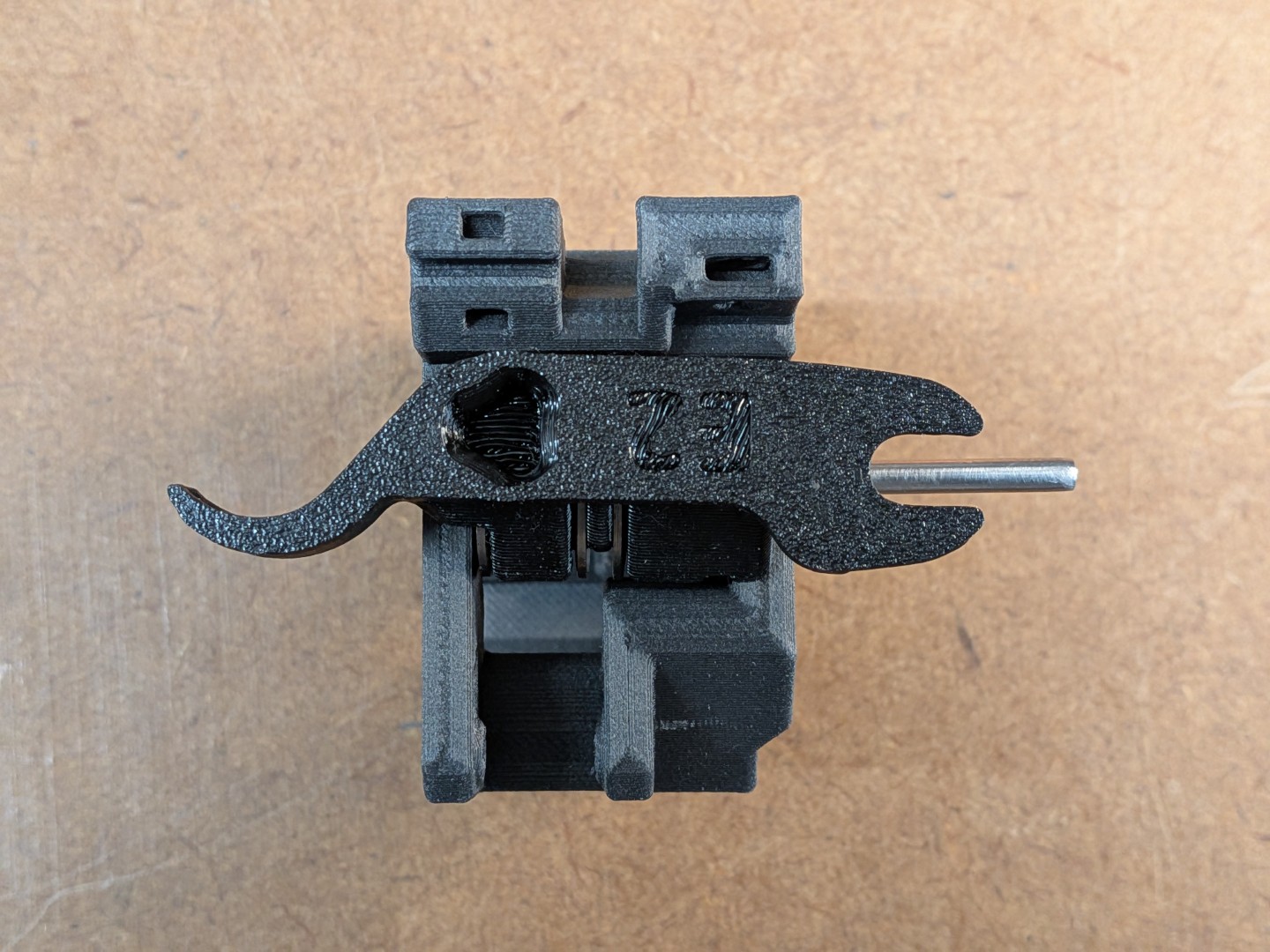
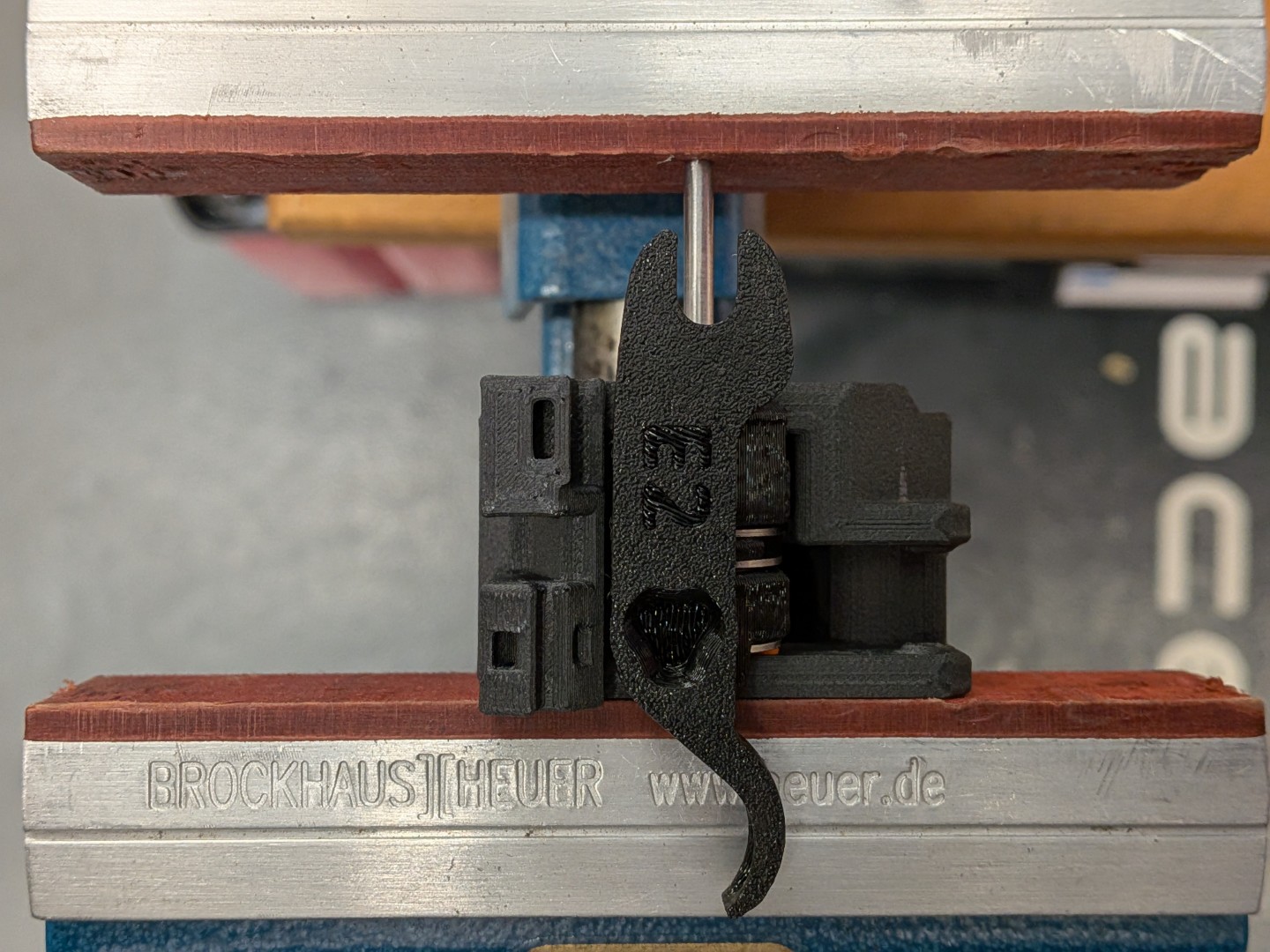
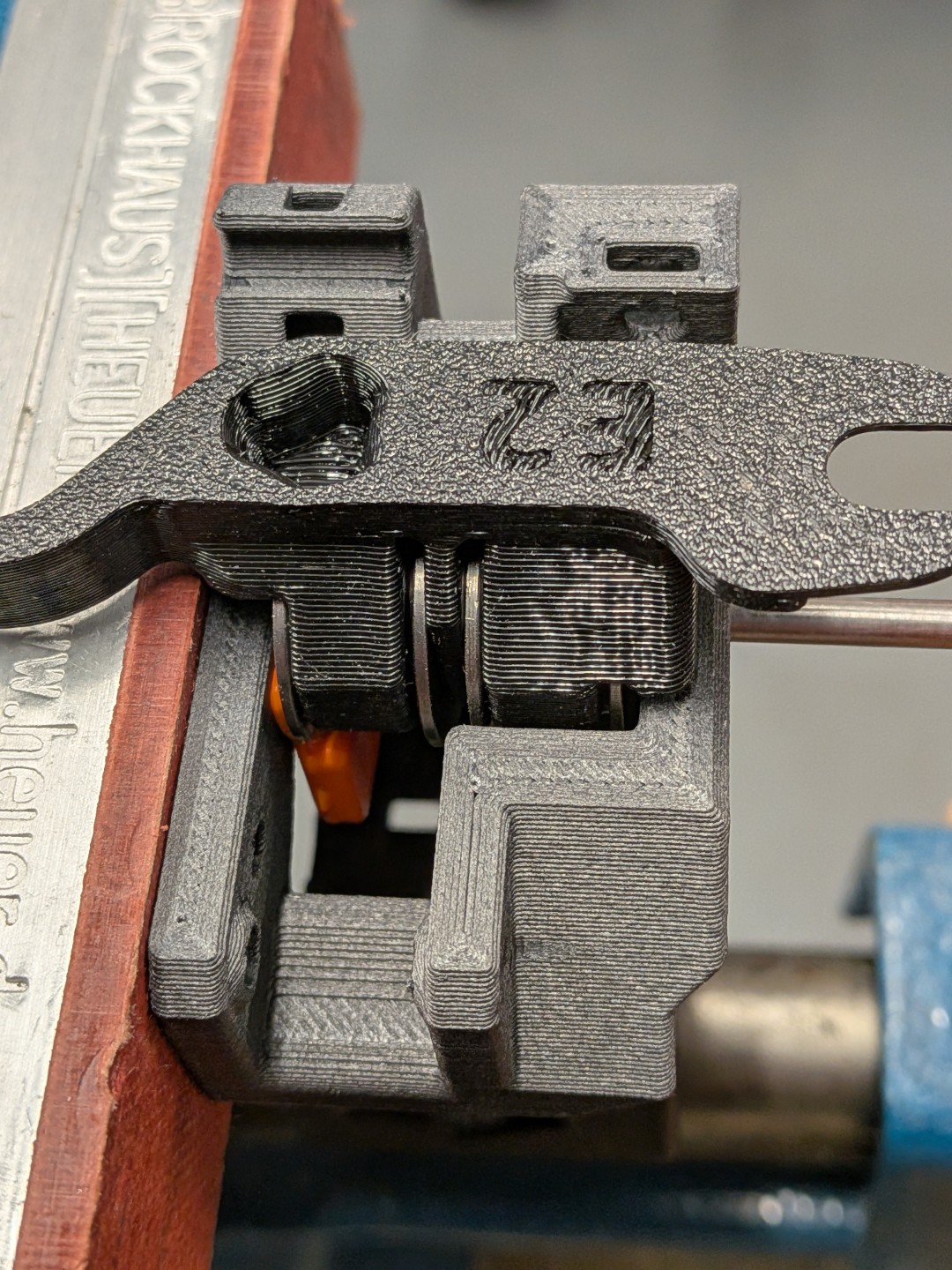
Required Tool: Parallel-press tool or vise to ensure straight pin insertion for all components. |
Required Pin Length:
|
Example: Belt Tensioner
 |  |  |  |  |
 |  |  |  |  |
Example: Motor Mount Stack Assembly
 |  |  |  |
 |  | 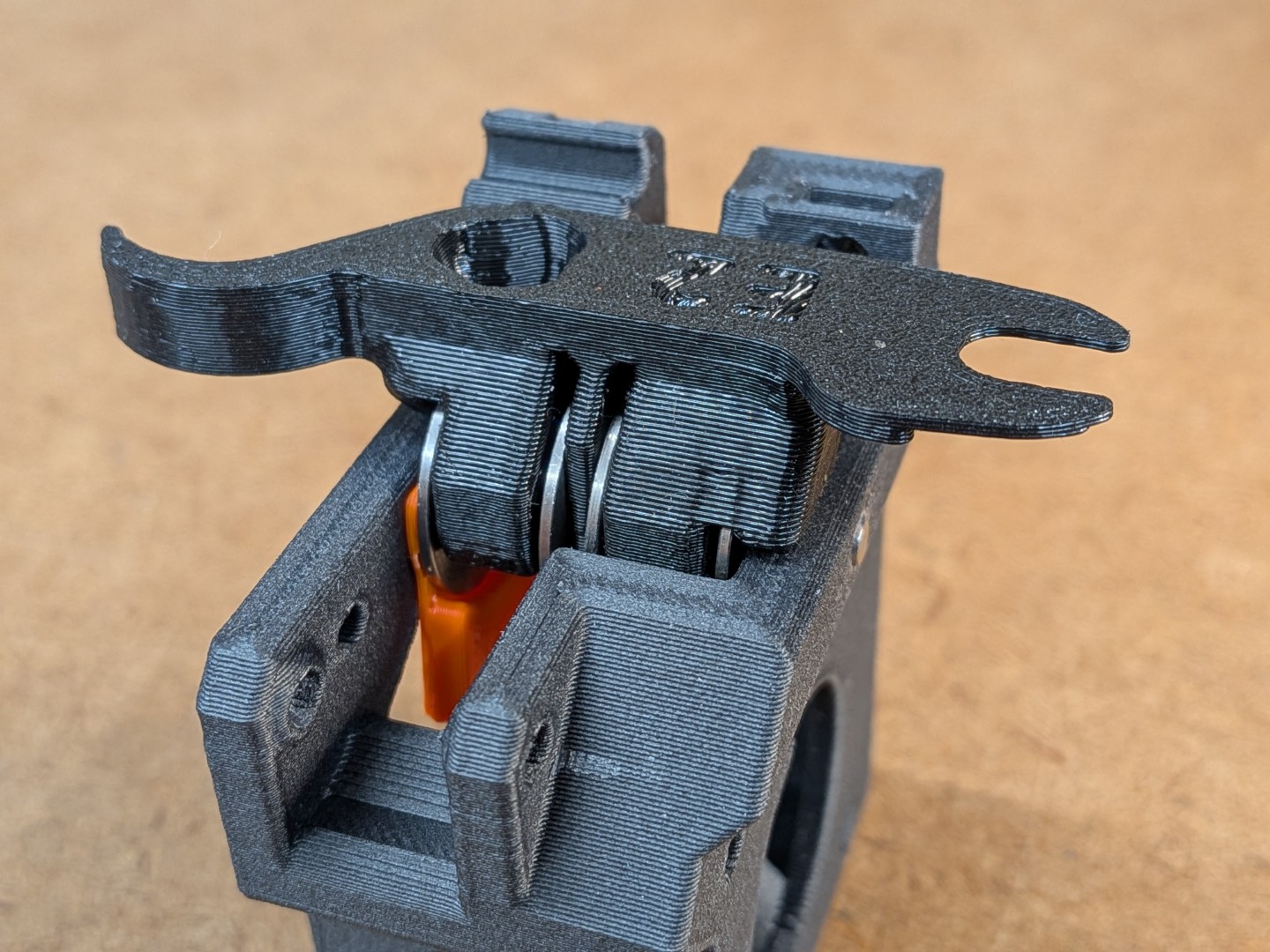 | 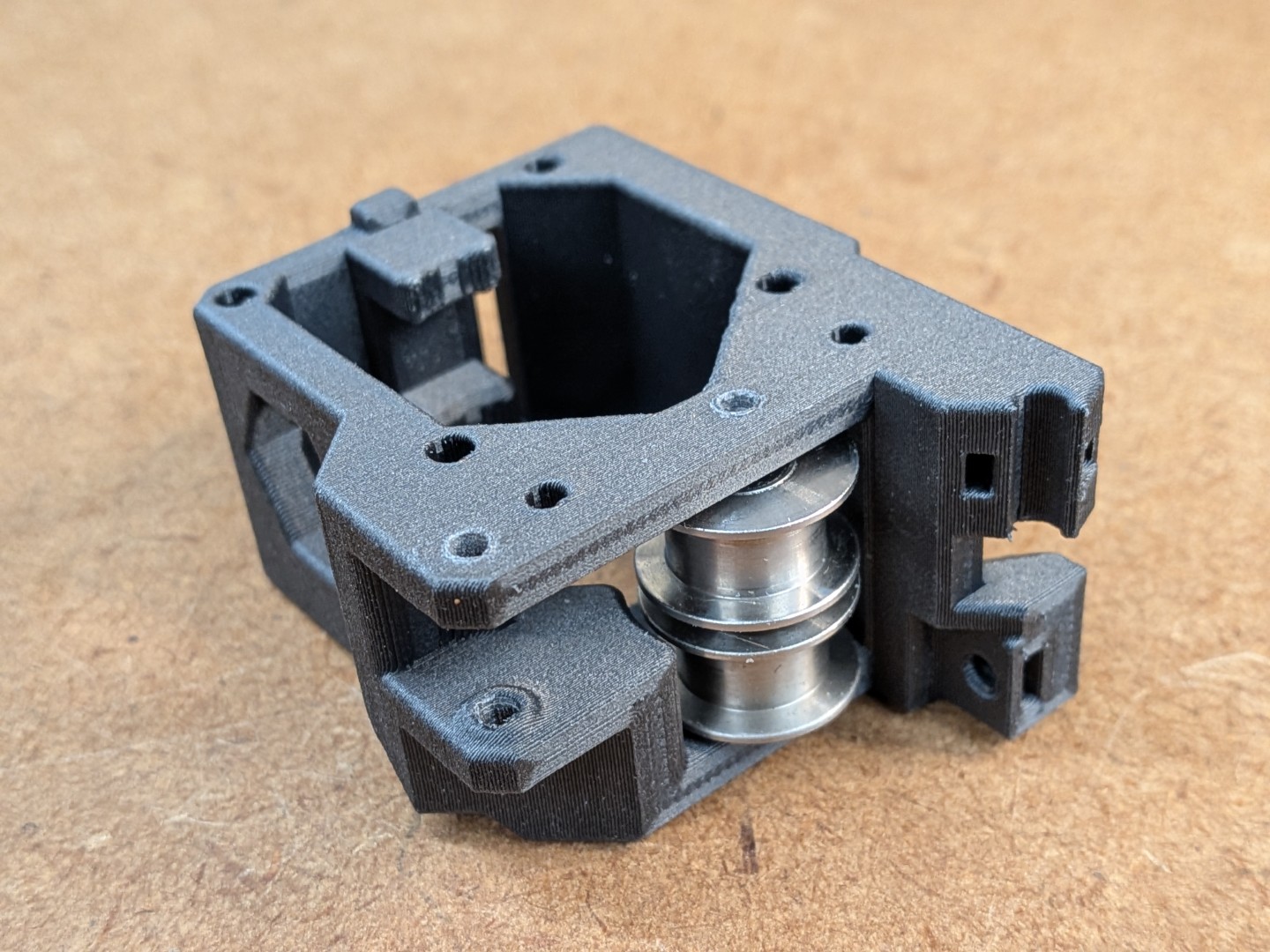 |
 | 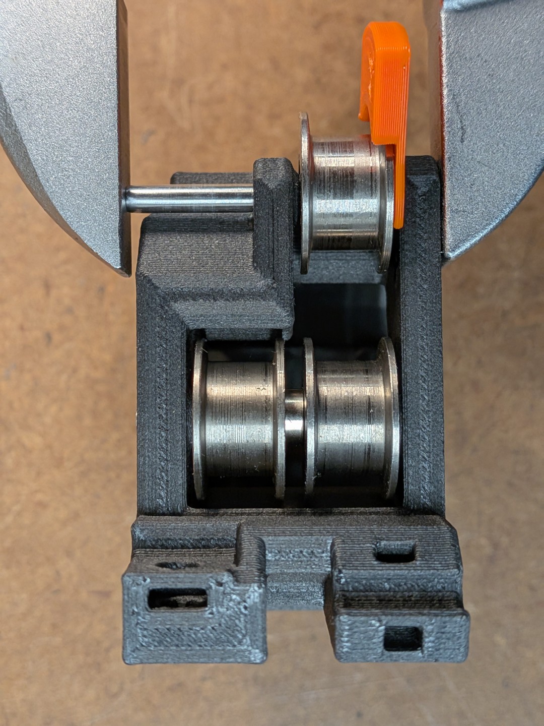 | 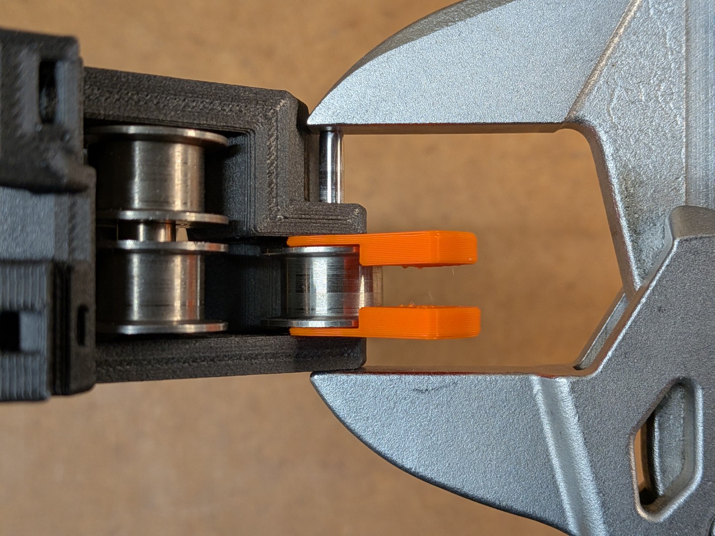 |  |
Assembly Process
Initial Pin Insertion
|
Idler Installation
⚠ If the alignment is not correct and you apply too much force you will push the bearing into the idler. This must be avoided. If it happens, replace the idler and if you are like me: Just order a spare one right upfront and chances are good that you won't mess it up.
|
Final Pin Installation
For all pins:
Be aware:
|
Quality Checks
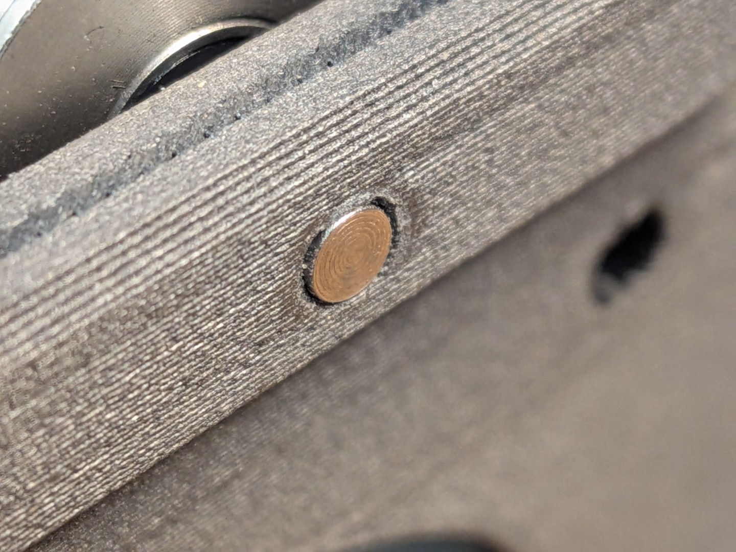
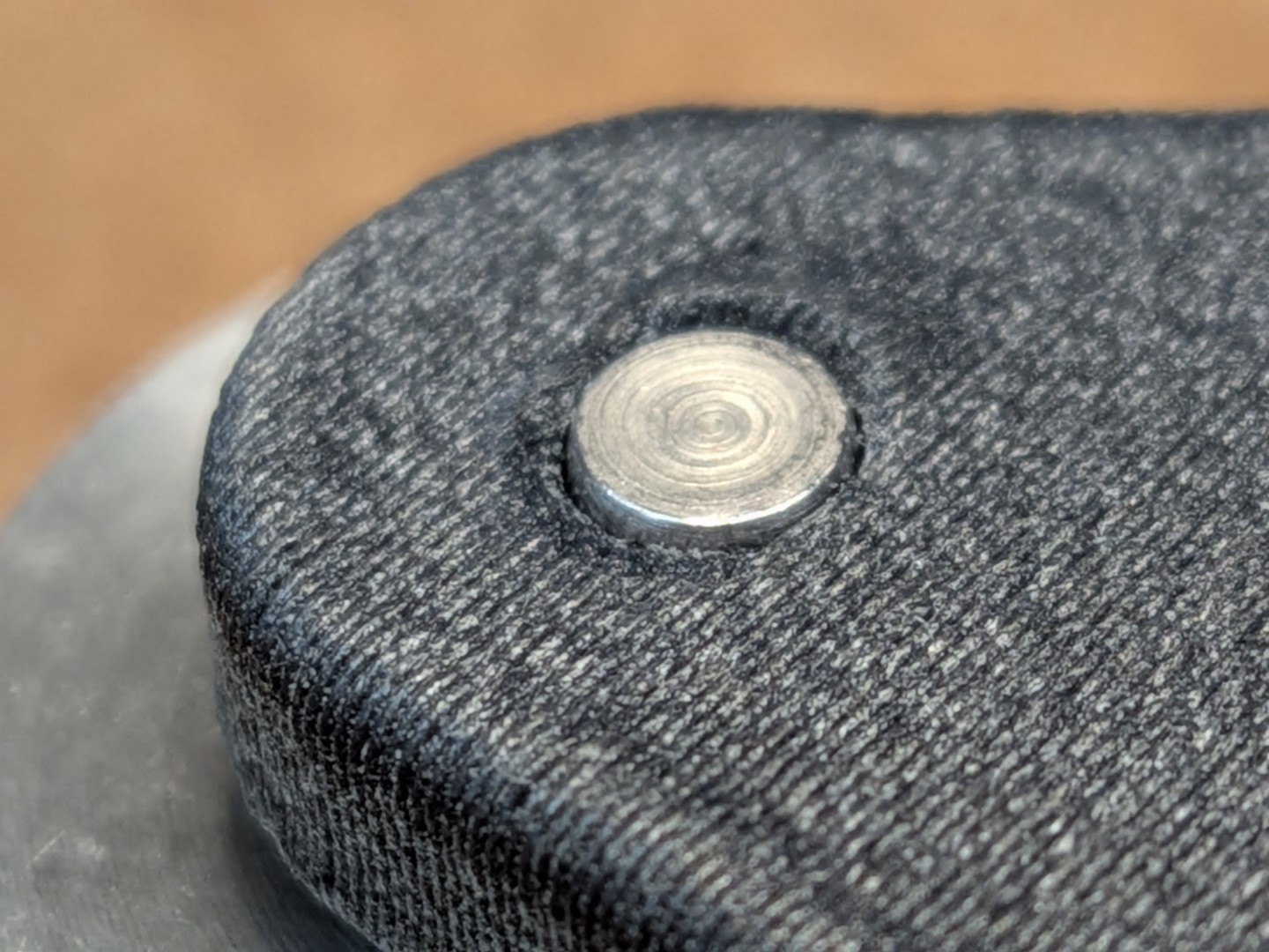
Verify that the pins are flush with the outer surface. | Confirm idlers rotate freely without binding. Check for proper alignment and smooth operation. | Check that the bearings are flush with the idlers. They must not be pushed inward. | Make sure the layers haven't separated. There should be no visible stress marks on the printed parts. |
 |  |  |  |
Print Settings
Recommended print settings:
Filament: PC-CF
Layer Height: 0.2mm
Infill: 40%
Perimeters: 4
Top/Bottom Layers: 5
Support: No
BOM
3mm Steel a Pins:
18mm: 3 pcs
20mm: 5 pcs
30mm: 2 pcs
Toothed Idler (Optional):
2GT-20T: 2 pcs (e.g. these idlers by Mellow, option “20T with T”)
Heat Set Insert (Optional):
M3x5x4 Heat Set Insert (Voron Spec): 2 pcs
CAD Files and Customization
Parametric CAD files are provided for this modification. All components have been modeled from scratch (no mesh remixes) to ensure optimal precision, fit, and performance.
File Formats Available
Autodesk Fusion 360 (.f3d) - Full parametric model with design history
STEP files for universal CAD compatibility
STL files ready for printing
Customization Capabilities The Fusion 360 files include custom parameters that allow easy modification:
Pin Diameter Adjustment: Fine-tune inner diameters for perfect pin fit
Bearing Clearances: Modify tolerances for different bearing brands
Dimensional Scaling: Adapt for different printer tolerances
Design Variations: Create your own variants and improvements
Gostou deste modelo? Crie uma conta grátis para salvar seus favoritos e voltar a eles depois.
Criar conta