Você está no 3DFinder
Buscamos em Thingiverse, MakerWorld e Printables ao mesmo tempo para te dar o melhor de cada uma.
Descrição
About
In the industry, most machines have a stacklight so machine status is easily visible from afar. Let's do the same with a 3D-printer: This is a stacklight for the Prusa Mini+. It should be possible to adapt this to other 3D-printers.
Accompanying this project, I have also written a blog post with a bit more details about stack light usage in the industry: Stack Lights — blog.rahix.de
Details
The stacklight connects to the printer via the I2C bus on its expansion header (J23). A small PCB is needed which houses an I2C port expander and some relays for the 24V stacklight signals. All design files are included.
To control the stack light, M260 G-Codes are inserted into the print files which set the appropriate stacklight colors (needs firmware ≥6.1.2). This has the advantage that no firmware modification is needed. However, there are some limitations: The stack light cannot be updated in certain abnormal situations as shown below.
| Situation | Stack Light Signal | Recommended Color |
|---|---|---|
| Power On/After Power Interruption | FAULT | ORANGE |
| Print Started/Running | OPERATE | WHITE |
| Print Completed/Ready to remove | READY | BLUE |
| Print Paused on Color Change | READY | |
| Print Paused on Slicer Pause | READY | |
| Print Aborted | not possible via G-Code | |
| Print Paused Manually | not possible via G-Code |
Additional Parts
In addition to the printed parts, you will need:
| Amount | Part | Link |
|---|---|---|
| 2x | M5x8 countersunk screw (e.g. DIN 7991/ISO 10642) | |
| 2x | Slot nut/Hammer nut for 8mm slots (alternatively, you can print one) | |
| 4x | M3x8 cylinderhead screw (e.g. DIN 912/ISO 4762) | |
| 2x | M3x8 countersunk screw (e.g. DIN 7991/ISO 10642) | |
| 6x | M3 L5.7 threaded inserts | CNC Kitchen |
| 4x | M5x16 cylinderhead screw (e.g. DIN 912/ISO 4762) | |
| 4x | M5 nuts (e.g. ISO 4032) | |
| 1x | Molex 0513821000 Connector Housing (for the J23 expansion connector) | DigiKey |
| 10x | Molex 0561349100 Crimp Socket (for the J23 expansion connector) | DigiKey |
| 1x | Automotive Add-On Circuit (for stealing the 24V DC from the heater fuse) | Details on the Prusa Forum |
| 1x | Dupont Pin (either bare or pre-crimped to a wire, ideally with a cross-section ≥0.34mm²) | |
| 1x | Stacklight Controller PCB (check the included design files) | |
| 1x | 3-color stacklight 24V DC, NPN |
Recommended Printing Parameters
| Orientation | Print in the provided orientation of the STL file |
|---|---|
| Support Material | Print without support material |
| Layer Height | 0.2 mm |
| Nozzle Diameter | 0.4 mm |
| Material | PETG |
Build Instructions
1 - Stacklight Controller PCB

- Check the included KiCAD project archive for the PCB and BOM. There is also an iBOM (HTML) for easy assembly.
- Don't be confused by the empty footprints on the right — these can be used for one more controllable 24V output, but are not needed for the standard stack light usage.
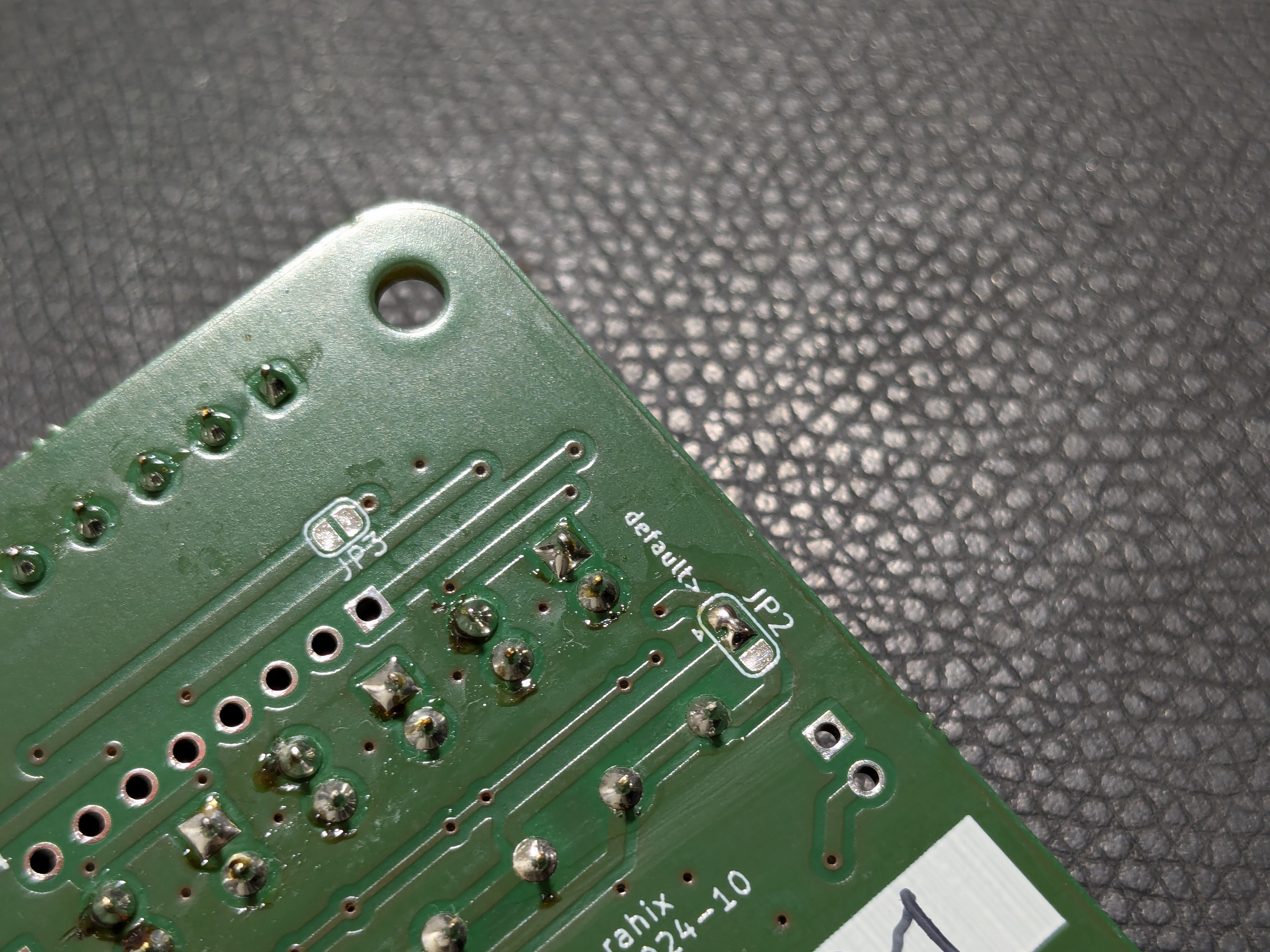
- Make sure to close the three-way jumper on the back into the direction that's marked “default”.
2 - Installation
- Install 6 M3 threaded inserts into the printed enclosure. 4 into the standoffs where the PCB is mounted and 2 into the appropriate holes for the lid.

- Install the enclosure to the side of the Prusa Mini+ using 2x hammer nuts and 2x M5x8 countersunk screws.
- Install the stacklight controller PCB into the enclosure with 4x M3x8 cylinderhead screws.
- Attach the stacklight to the mounting hole pattern on the top, with 4x M5x16 screws and nuts. The wires from the stacklight should enter the enclosure through the center hole.
3 - Wiring Harness
- Terminate the stacklight wires to the top connector of the PCB (J1) as detailed in the wiring diagram. You can use the ziptie mounts in the enclosure for wire management.

- Prepare the printer-side wiring with the Molex connector for the expansion port, the add-on-circuit for the 24V and the dupont pin for the GND. On the stacklight controller side, the wires terminate in the WAGO picoMAX connector. Check the wiring diagram for details.

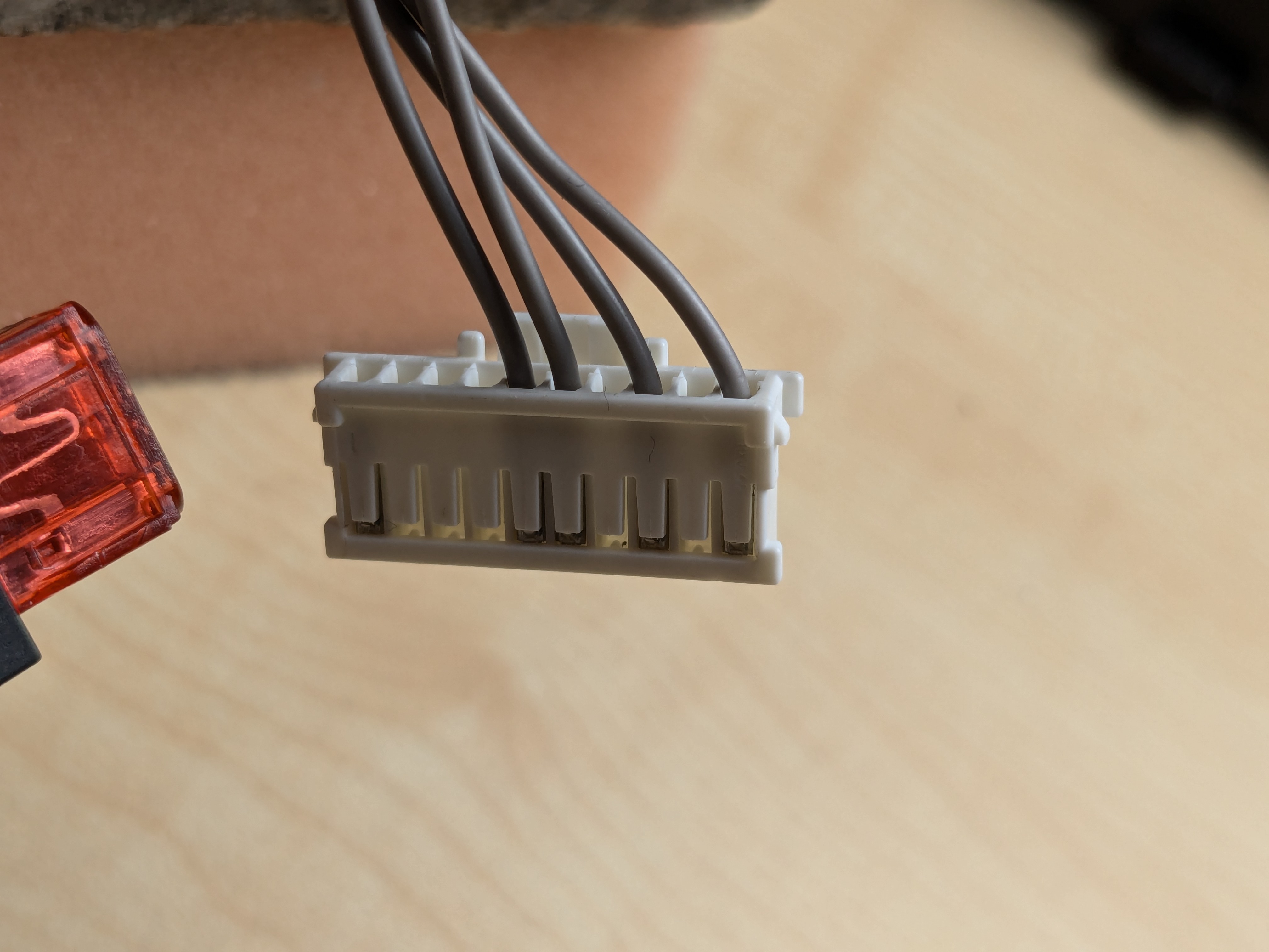
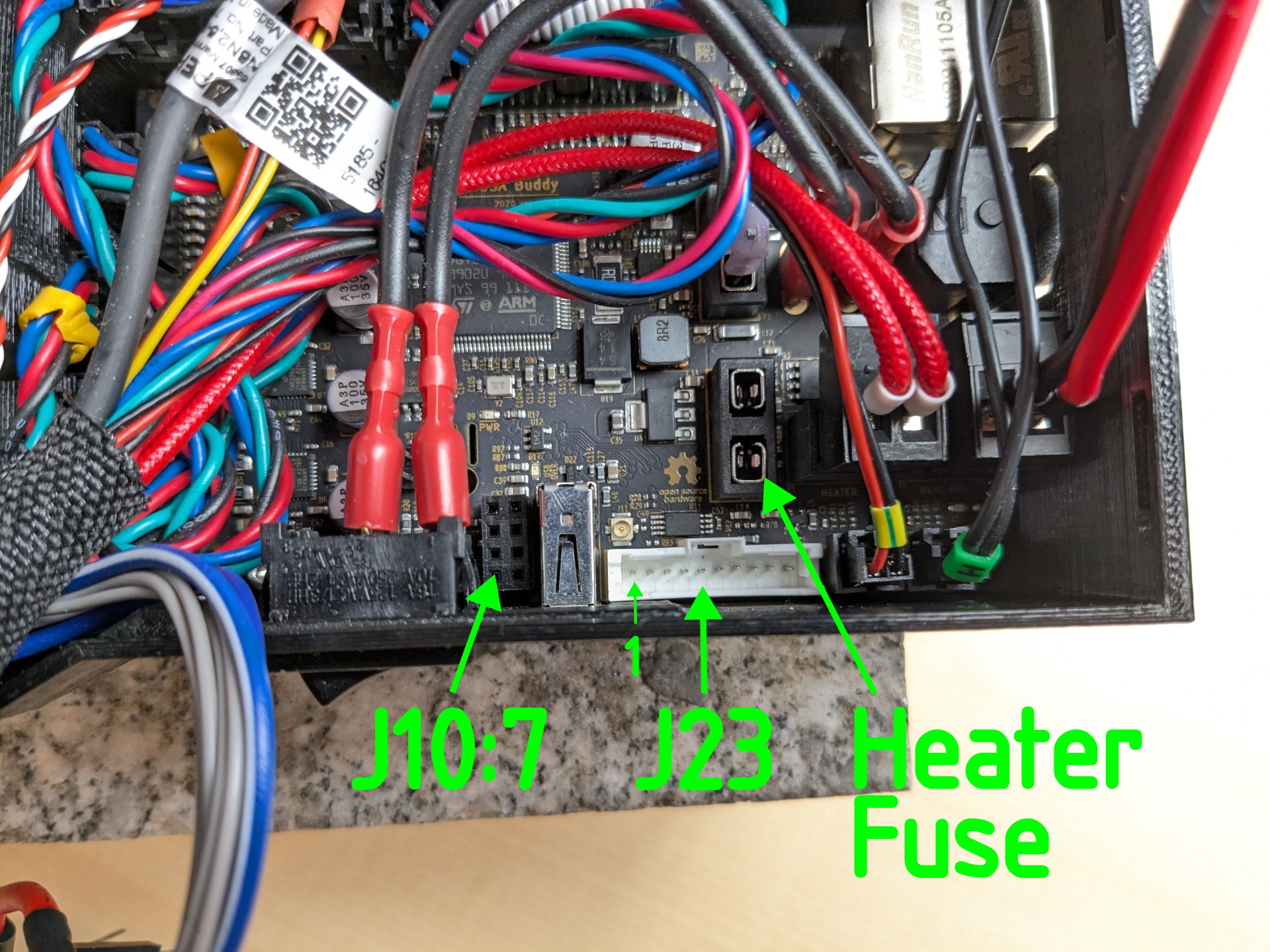
- Plug the connectors into the appropriate locations on the Prusa Mini+ board. Again, check the wiring diagram. Pull the heater fuse and place it into the add-on circuit plug. Here is an overview of the connector locations:
- With all the wires in place, it looks like this:
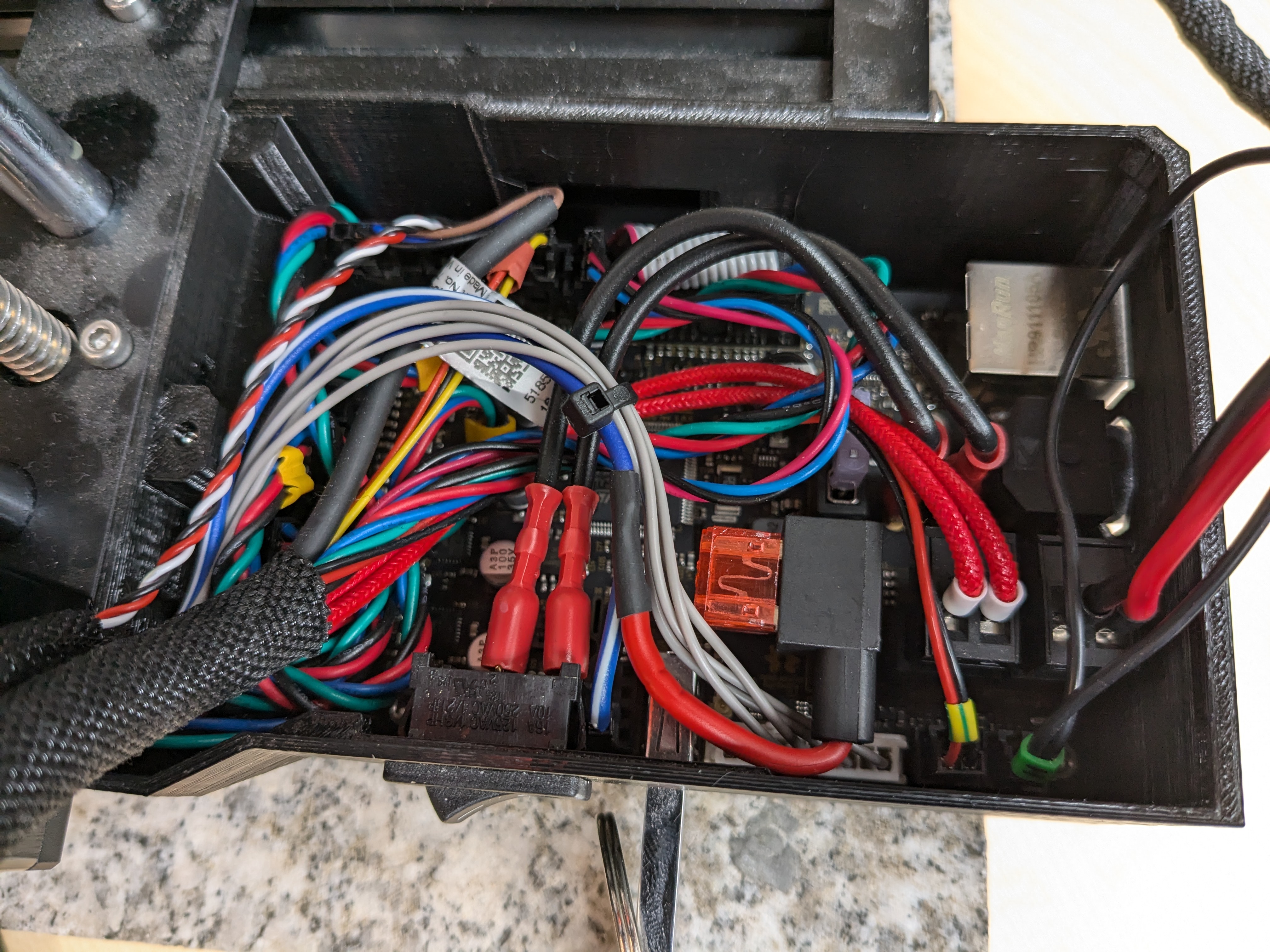
- Run the wires in the slot profile next to the existing stepper wires. Plug the picoMAX connector into the stacklight controller.

4 - Configuration
You are now ready to turn on the system. You will need to modify your printer profile a bit so the g-codes to control the stacklight are emitted. Here are the lines that need to be added (and some of the context lines that are there by default):
Start G-Code
G90 ; use absolute coordinates M83 ; extruder relative mode; Stack Light Init M260 A32 M260 B1 ; Output Register M260 B1 ; Fault Off M260 S M260 B3 ; Configuration Register M260 B0 ; All outputs M260 S
M104 S170 ; set extruder temp for bed leveling M140 S[first_layer_bed_temperature] ; set bed temp
End G-Code
G4 ; waitM104 S0 ; turn off temperature
M190 R50 ; Wait for cooldown to a touchable temperature ; Stack Light Color Change M260 A32 M260 B1 ; Output Register M260 B3 ; Fault Off & Ready M260 S
M140 S0 ; turn off heatbed
Color Change G-Code
; Stack Light Color Change M260 A32 M260 B1 ; Output Register M260 B3 ; Fault Off & Ready M260 SM600
; Stack Light Color Change M260 A32 M260 B1 ; Output Register M260 B1 ; Fault Off & Operate M260 S
Pause Print G-Code
; Stack Light Color Change M260 A32 M260 B1 ; Output Register M260 B3 ; Fault Off & Ready M260 SM601
; Stack Light Color Change M260 A32 M260 B1 ; Output Register M260 B1 ; Fault Off & Operate M260 S

Gostou deste modelo? Crie uma conta grátis para salvar seus favoritos e voltar a eles depois.
Criar conta