Você está no 3DFinder
Buscamos em Thingiverse, MakerWorld e Printables ao mesmo tempo para te dar o melhor de cada uma.
Descrição
This is the official V-Spooler motor modification, with the following features:
- A strong 12v max 260RPM motor
- A 3 position switch to control direction (clockwise, off, anticlockwise)
- A knob that controls the speed, which also turns the motor off when turned down
Please note this mod will not work for V-Spooler X for which a slightly different one has been created, which you can find here.
Our manufacturing partner VisionToCreate3D provides hardware kits, printed parts and fully assembled V-Spoolers at their store, for which Fyrby Additive receives a percentage. You can find the V-Spooler Motor Mod kits available here, please be sure to select the right one!
A 3D colour preview of this model is available by clicking here, phones and headsets can use an optional AR preview with the button at the top.
Please note the documentation is now provided in PDF format here on this page above the comments.
Safety Warnings
If you are self sourcing, this speed is really fast enough and generally it doesn't feel very safe to use a faster motor. I tried a few motors so you don't have to. Maybe you want to not use the 260RPM motor at full speed if you are not in a hurry, and have a bit of mechanical sympathy!
If your unit jams at speed it may break V-Spooler destructively or possibly cause a spool to go flying across the room, so consider not letting children using it, and also find a place where it can be used safely if you want to go fast.
Printing Recommendation
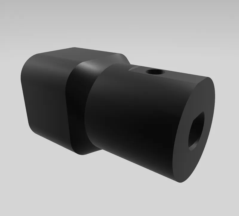 | The adaptor part that attaches to the motor can be susceptible to wear, following reports from users.
If you have a resilient carbon or glass fibre engineering plastic available it will benefit from being printed in that. Else, please use your most resilient plastic for this part. I am using PC-CF which seems to work well. |
Changes
| Version | Changes |
|---|---|
| 2.0 | Modify overall design to be based on the V-Spooler X motor mod. These changes make various points of the mod stronger and it looks much nicer. The ability to screw the adaptor to the motor axle has been removed. |
| 1.1 | Enlarged the opening in the upright so a screw may be used on motor adaptor to prevent excess wear to the adaptor. |
| 1.0 | Initial version. |
Bill Of Materials
It would be great if you can support me by buying the hardware kit from my manufacturing partner as listed above, however we provide these instructions below to help you self-source the build should you want to.
| The correct motor controller. I find it easiest to search for 1203BB and look at the pictures. Note that this one has a silver knob and a separate switch to control the direction as pictured. The heat sink is often at a slight angle. This should be a 12v part but may support other voltages. |  |
| Motor with part number 5840-555-CE. As this motor has a few variants I am using the 12V 260 RPM version with an 8mm output shaft. |  |
A 12v DC adaptor to match the DC connector. I am using a 5.5mm OD 2.1mm ID barrel connector for the item below. It should support at least the stall current of the motor which is 6.5A, so a 78W or better 12v power supply.
Usually having some overhead is nice, so a higher rated 12v supply may be a good idea. |  |
DC Jack. The one that fits can be found by searching for “DC099 Wired” - it is available with cable pre-soldered, which saves a little work. It looks as pictured to the right.
Ensure to get one that fits your DC adaptor. They seem to be available to support either a 5.5mm OD and 2.1 or 2.5mm ID. |  |
17x M3 inserts, Ruthex or CNC kitchen work great.
Note the Bambu Lab inserts have a different outside diameter and will not work well. |  |
| |
| 2x 30cm wires for the motor | |
| Crimp plugs for the motor or the ability to solder wire to the motor terminals. |
Electronics Preparation
| Your controller may be pre-assembled as pictured to the right. We need to disconnect a couple of parts to be able to install it inside the model. |  |
| First we are going to disconnect the direction switch. Hold the cable close to the connector indicated and pull it out of the connector carefully. | 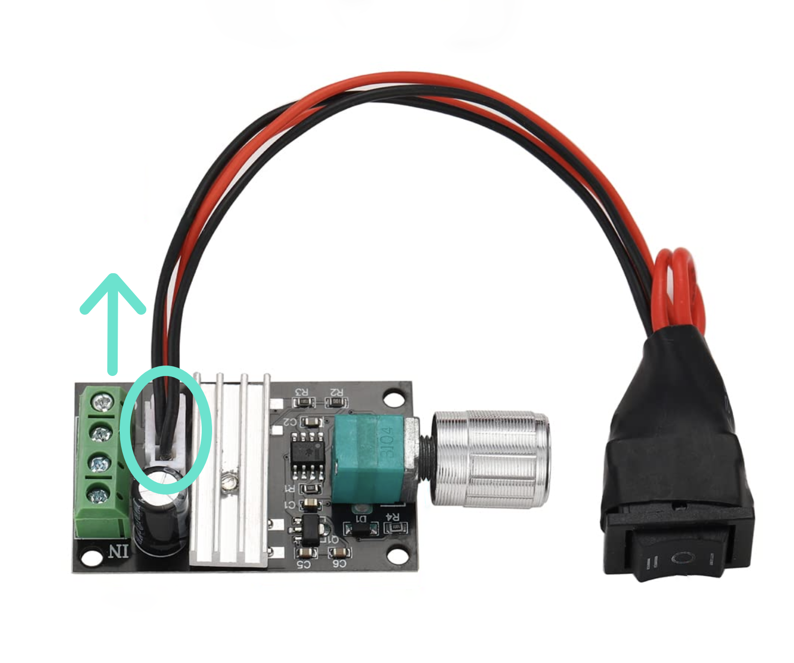 |
Now we are going to remove the speed control knob. Hold the part of the component by the circled area and pull the knob off carefully.
Behind the knob there may be a nut and washer. Save these for later! |  |
Take the cable for the motors and either solder it to the terminals, or crimp appropriate connectors and attach them.
You need to use roughly 30cm length of cable, which leaves a bit spare to trim down later. |
