Você está no 3DFinder
Buscamos em Thingiverse, MakerWorld e Printables ao mesmo tempo para te dar o melhor de cada uma.
Descrição
SpaceX Dragon Lander
A mix / mashup of the SpaceX Dragon II with the classic Estes Mars Lander.
I designed the lander base around Mech-G's Vintage Mars Lander design found on Thingiverse. It was a great starting point.
This assembly video should help make you feel comfortable with building the model, the details listed later on this page should answer any questions you may have. (we'll see)
UPDATES:
(I'll be posting these near the top so they're easier to find)
- CLASSIC NOSE CONE
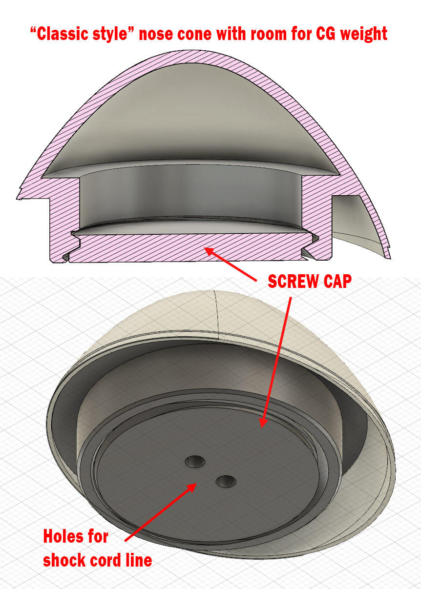
Classic Nose Cone: Some folks have had problems with the unusual hinge mechanism, so I updated it to work more like a classic nose cone, complete with a chamber where you can add additional nose weight.
Two holes in the screw cap allow you to thread shock cord through to attach it to the recovery system.
I use needle nose pliers to hold the screw cap via the holes to make it easier to thread in.
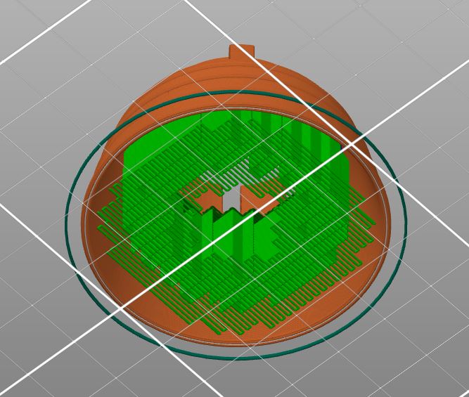
You will need to print the nose cap with supports.
- NEW LADDER
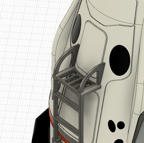
The V2 version of the ladder has slots in the upper step, similar to what I used for the Gemini Lander.
I've removed the original design so if you've downloaded this recently you should have this update.
Springy Legs
For the spring loaded legs, I used 7/32 x 1" springs extension springs - they came in an assortment pack I got from Amazon - but you can use rubber bands. Here is a link to the assortment pack.
Filament pins
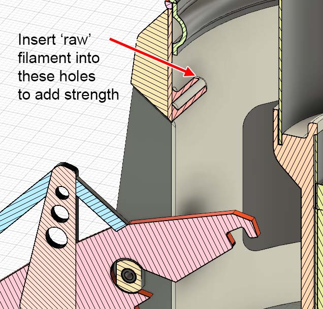
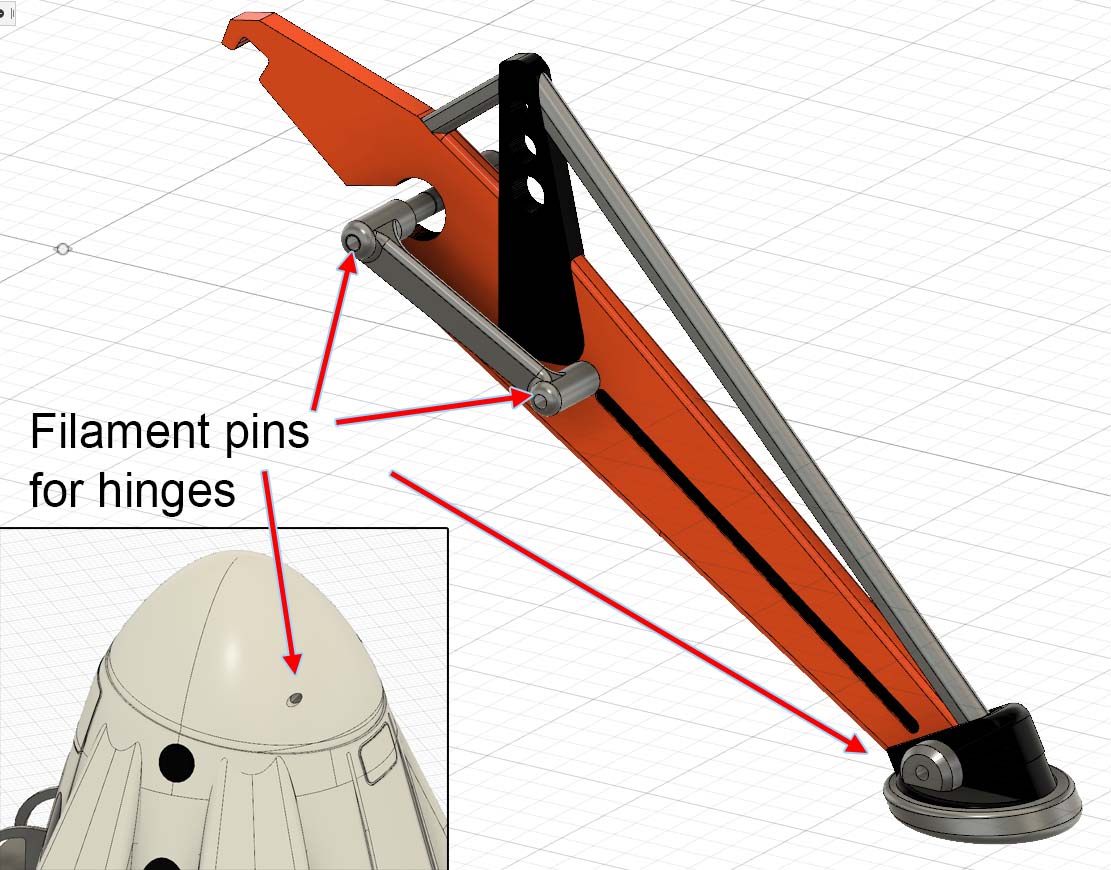
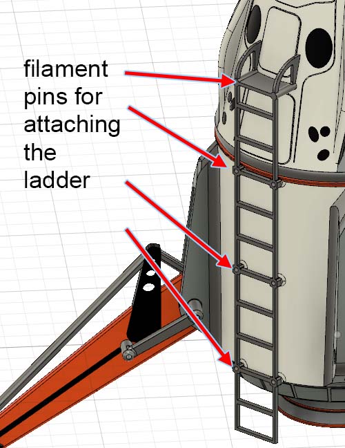
In many places I use ‘raw’ filament as hinge pins or means of strengthening a post (the spring posts or stand mount). You may find you need a small drill to round out the holes so the filament fits in.
The holes for the launch rod can be used as is or will accommodate a standard Estes launch rod tube.
The Ladder
The ladder requires the top and bottoms halves of the lander be assembled before you attach it. It is NOT supposed to be glued on as that would prevent you from opening the lander at a later time. It's kind of fragile and may not survive flight but we'll see eventually.
I do CA glue the pins into the ladder to help keep them attached and you may want to drill out the pin holes at the joint where the top and bottom mate. This assures alignment and acts as a lock for the Dragon crew section.
Rocksim File
I've included a RockSim file that I think is setup correctly to simulate this odd bird.
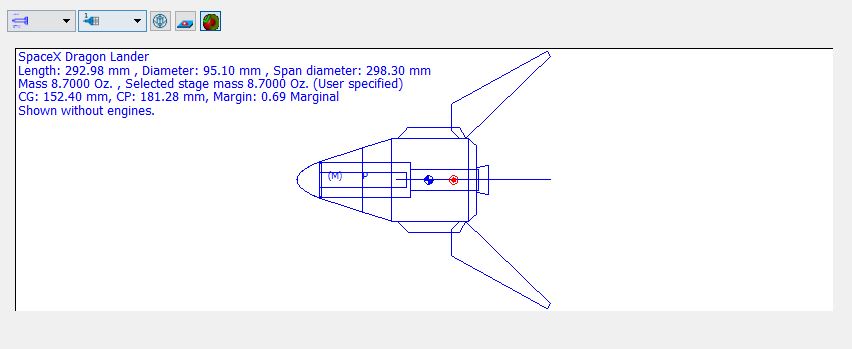
Note: this website doesn't allow for files with an RKT suffix, so I renamed it to be .TXT. You can either load this by forcing Rocksim to read it or simply change the suffix back to RKT.
I currently have a 24" Estes plastic chute, I plan to make a steel wool baffle and use kevlar string for the shock cord. More details will come as I test those components.
Printing Notes
- I printed the entire model with PLA at .2 layer height but drop that down to .15 for the nose cap and hinge.
- The hinge needs to be carefully bent to free up the pivot.
- Printing in color will take a few days in total and using Black in the Dragon section required me to to set the purge volume for the black to 500! (and even then I still got bleed)
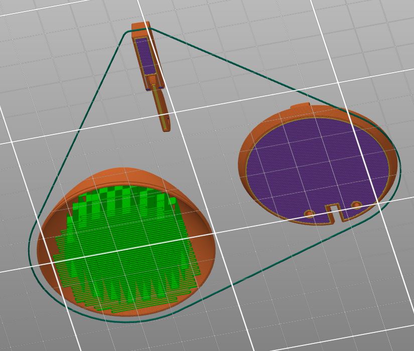
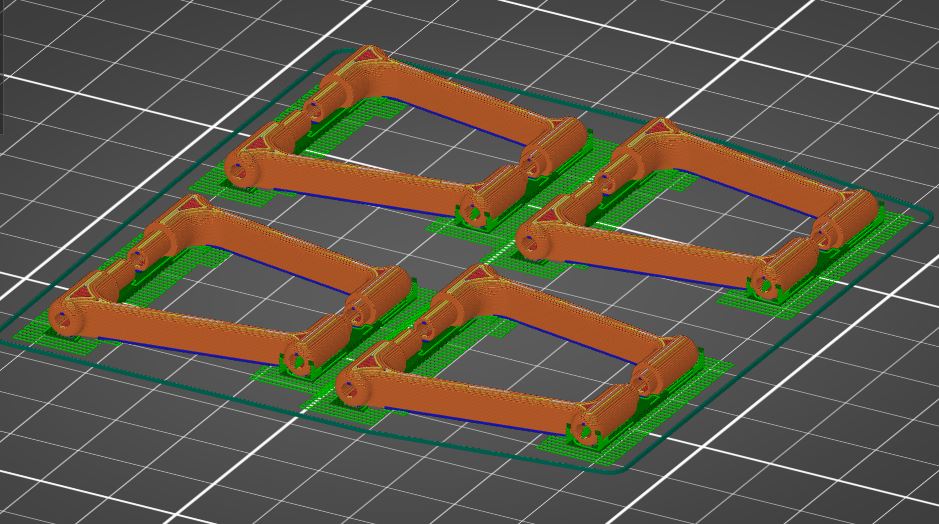
- Very few parts require supports but the nose cap, support struts and nozzle benefit from them.
The Nose cap has an internal flat surface that will need support during printing.
The Leg Support Struts have small axles that need to be supported.
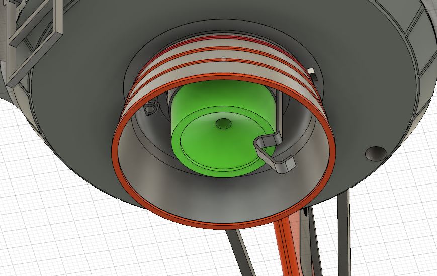
The Nozzle will need the center supported when printing.
Screw that
In a couple places (nozzle and nose cap) I use small screws for assembly - an M1.7 Nickel-Plated Steel Phillips Pan Head. You don't have to use this exact screw - and if you want you can use glue for the nose cap (but not the nozzle). Anyway here is the screw assortment I draw from for this.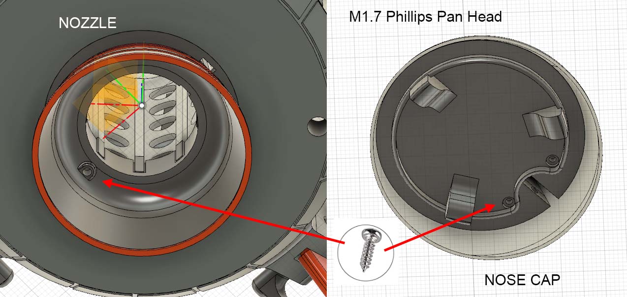
The Nozzle
You may want to print a few of these or not fly it with the nozzle. I'm not certain how well it will hold up to the heat of the motor exhaust.
If you do fly with the nozzle it has to be put in place after the motor is inserted as it also acts to lock down the motor clip.
The Nose Cap
It is modeled to function similar to the Dragon's and I like not having to attach it to the recovery lines. That said, this is untested with a real life ejection charge so we'll see how well it works. In all my ground tests using just air blown into the chamber, it blows back and the chute emerges. 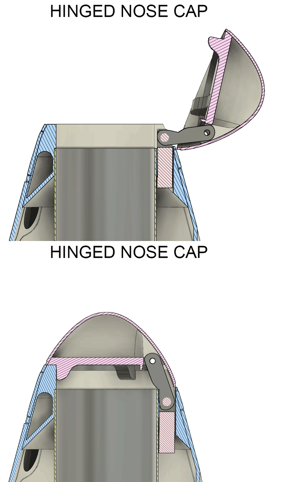
Non-printed parts needed
- BT-60 Body tube - 106mm length
- BT-50 Body tube - 79mm length
- Plastic Parachute - 24" should do it (unknown)
- Standard Estes Motor Hook
- Small pan head screws
- Launch Lug
Optional stuff
Note: I consider these optional because there are other more traditional ways you can attach your parachute to the inner BT-60 tube. This is just a design I wanted to try.
- Paperclip (optional)
- Steel Sponge (optional)
- Kevlar String (optional)
Launch Pad Spacer
There are a zillion ways to offset a rocket like this on a launch rod, but because it was trivial, I designed a nice little spacer that gets the job done easily.
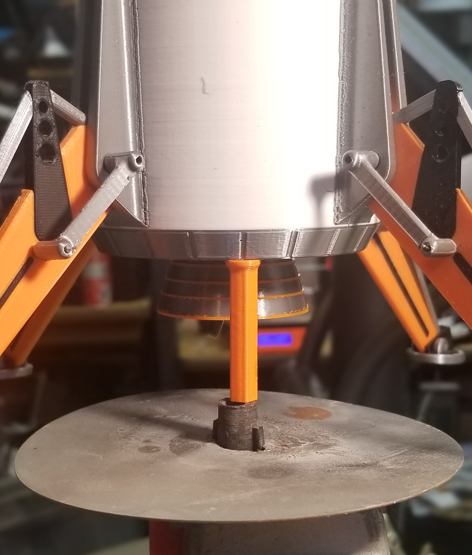
Loading onto a launch pad
Because there is an air gap between the upper and lower launch guide openings, it will take a little practice to get it on the rod. It may pose a challenge on pads where the rod is at waist height or higher. If the Rod can be removed it would be easier to feed it through first then re-attached to the pad. I'll be looking into ways to improve this.
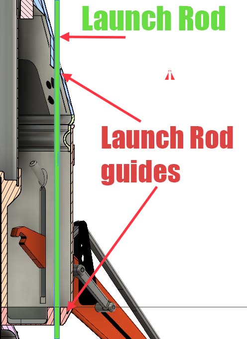
3D Model
For those of you wanting to modify and grow this design - I've included the Fusion 360 and STEP exports in the files section here.
FEEDBACK WANTED!
Because I live in a fire sensitive region of California, I've not test flown this. If you build and fly this PLEASE send videos, pictures and feedback!!

Gostou deste modelo? Crie uma conta grátis para salvar seus favoritos e voltar a eles depois.
Criar conta