Você está no 3DFinder
Buscamos em Thingiverse, MakerWorld e Printables ao mesmo tempo para te dar o melhor de cada uma.
Descrição
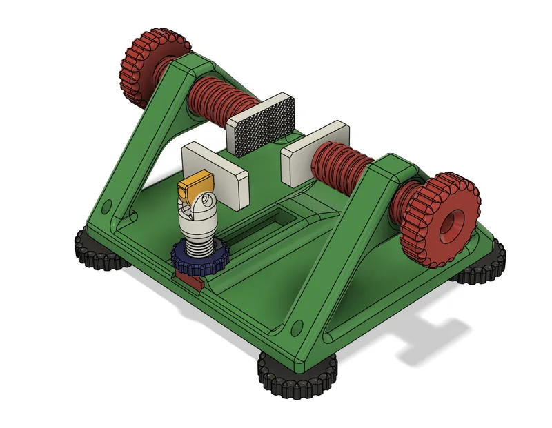
This is a custom built PCB stand designed to aid with soldering and tinkering on PCBs.
The maximum width that this model can handle is 150mm. Simply assemble as described below and adjust side screws to whatever size you need.
Additional parts required for assembly:
- 9 x M4 threaded inserts
- 6 x M4x20mm
- 3 x M4x12mm
- 2 x 14mm diameter bearings (5mm bore, 5mm depth)
Optional but recommended: - 2 x M4 Nuts
Quantity of each file required to print:
- 1 x Stand_Frame
- 1 x Leg_Screw_Base
- 1 x Leg_Screw
- 1 x Rotator
- 1 x Leg_Nut
- 2 x Screw
- 3 x Clamp_End
- 4 x TPU_Foot
Part specific print instructions (0.2mm layer height recommended for all, PLA or PETG):
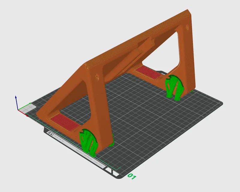
Stand_Frame: >25% infill (higher infill increases strength), only tops of large side threads require supports
e.g:
TPU_Foot: print in TPU to increase friction and reduce sliding
Other models: no specific requirements
Assembly
1 - Print files off as stated previously
2 - Place threaded inserts into all 4 TPU feet and screw M4x20mm bolt into the 4 respective holes on Stand_Frame, the feet should screw onto the bottom of the bolts that stick out of the bottom of the frame.
3 - Put threaded inserts into each of the 3 Clamp ends.
4 - Insert 14mm bearing into each large screw, the fitting can be tight so it may require some force to do this.
5 - Slide an M4x12mm bolt through the internal cavity in the screw and the bearing and place M4 nut on the end to secure bolt onto the bearing.
6 - Partially screw the large screw through the frame arms (without this step, it is impossible to get the large screw into the frame after the next step is complete!)
7 - Use your screwdriver to attach the clamp end onto the protruding bolt.
8 - Repeat steps 4-7 for the other large screw.
9 - Screw Leg_Nut onto Leg_Screw.
10 - Insert threaded insert into the bottom of Leg_Screw, and attach it to Leg_Screw_Base with M4x12mm bolt
11 - Slide this into the cavity on the frame
12 - Insert 2 threaded inserts into the holes on the Rotator (insert them into the side with the larger hole)
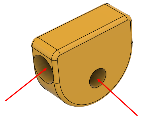
13 - Slide the flat end into the Leg_Screw and secure with M4x20mm bolt.
14 - Screw M4x20mm bolt into the other hole and attach final Clamp_End piece to it.
15 - Everything is fully assembled! Adjust Leg_Screw and the side screws to whatever size you need! It should look something like this: