Você está no 3DFinder
Buscamos em Thingiverse, MakerWorld e Printables ao mesmo tempo para te dar o melhor de cada uma.
Descrição
Design made from scratch with Solidworks and changed to Fusion for printing, in memory of the Scotland Engineer Robert Stirling, that came up with the first air engine in 1816.
Threads are made with 0.2 tolerance.
Bearings are printed and working.
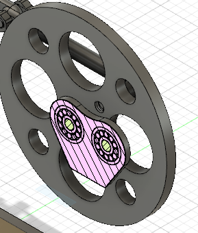
Moving parts, balance, rotors, pistons rods and junctions were tested for accuracy and dimensions.
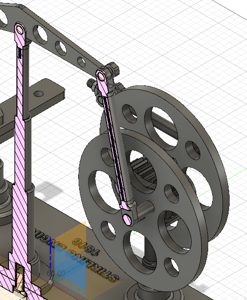
Intented for education.
Phase Relationship
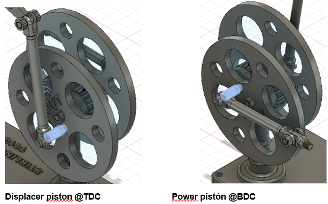
In a typical Stirling engine, the displacer piston and power piston operate with a 90-degree phase difference.
This means that when the displacer piston is at its TDC (fully up in the vertical cylinder), the power piston is either at its midpoint or nearing its BDC in the horizontal cylinder. This phase difference allows the gas to be appropriately heated and cooled, creating the necessary pressure variations to drive the power piston continuously.
TIMING
Check the assembly. If everything was fitted following this step-by-step procedure, there should be approximately a 90-degree phase difference between the flywheels.
This assembly depends on the thread position of the axle and the flywheel alignment. Ensure that the facing-out marks are aligned correctly. I recommend fully screwing in the flywheel as the threading starts, which will ensure it stays in the desired position when fully tightened. Note that while screwing, there is only one correct position; it’s a precise way to align junctions accurately. Don’t forget to complete the initial steps to match axle 1033 with the gears, as detailed in steps 5, 6, and 9, 10.
If there are big differences, please move position of only one axle 1033, has six sides, so you can rotate it 36º, which is the accuracy of this design, plus the gear tolerances and the rest of components.
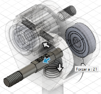
Place in position second gear with gear hole facing up.
To achieve the timing I rely on the thread start and the high detail of our printers.
3D of the displacer piston.
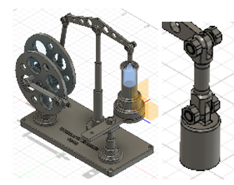
3D of the power piston.
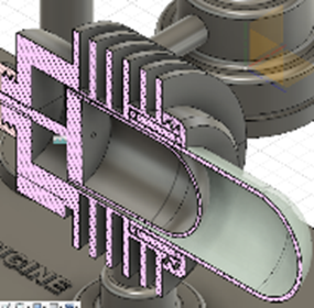
Every Plate plate is having all components needed for each part, the gear tower, the first flywheel, the balancer, the second flywheel, the displacer piston, and the power piston.
Hope you enjoy it, it is not only moving parts, which indeed requires a lot of work .
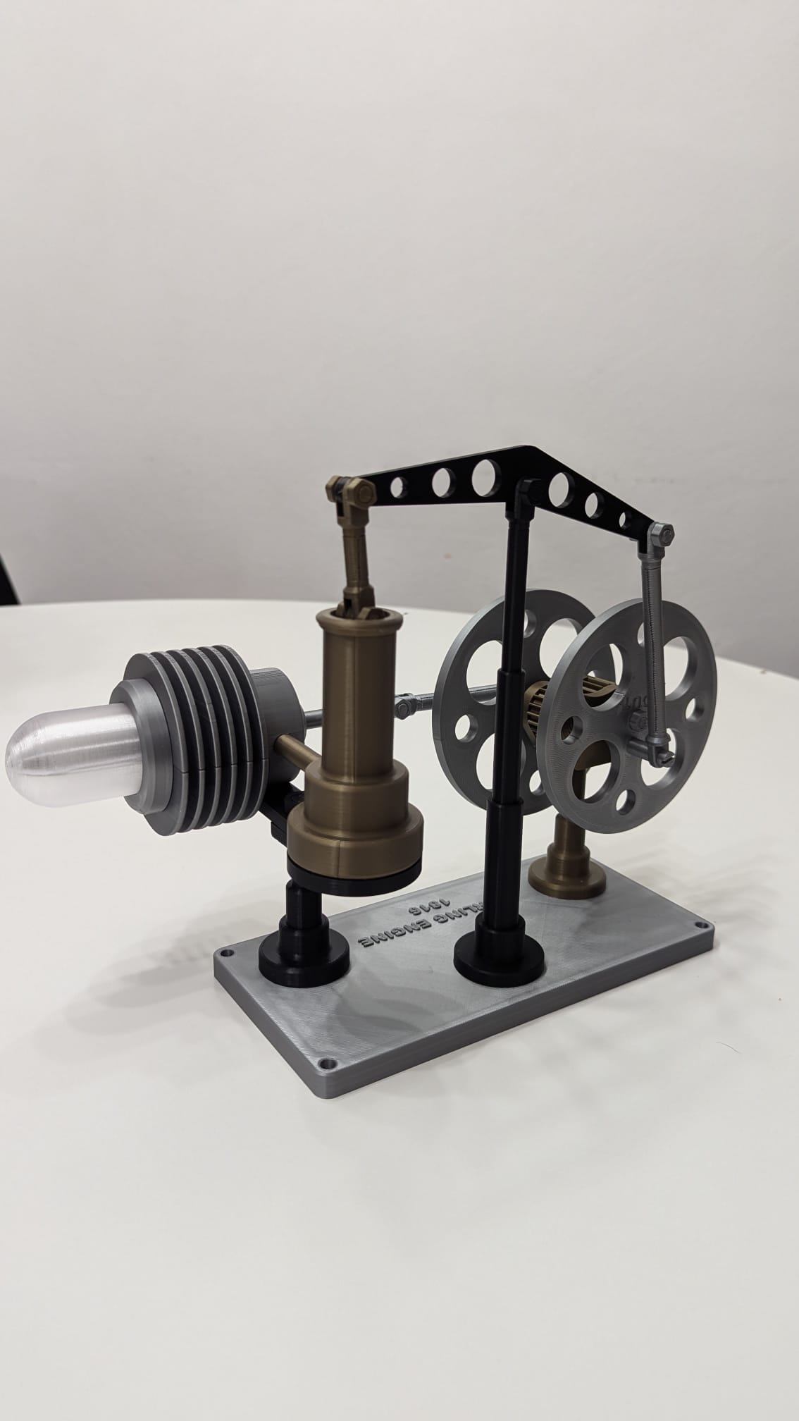
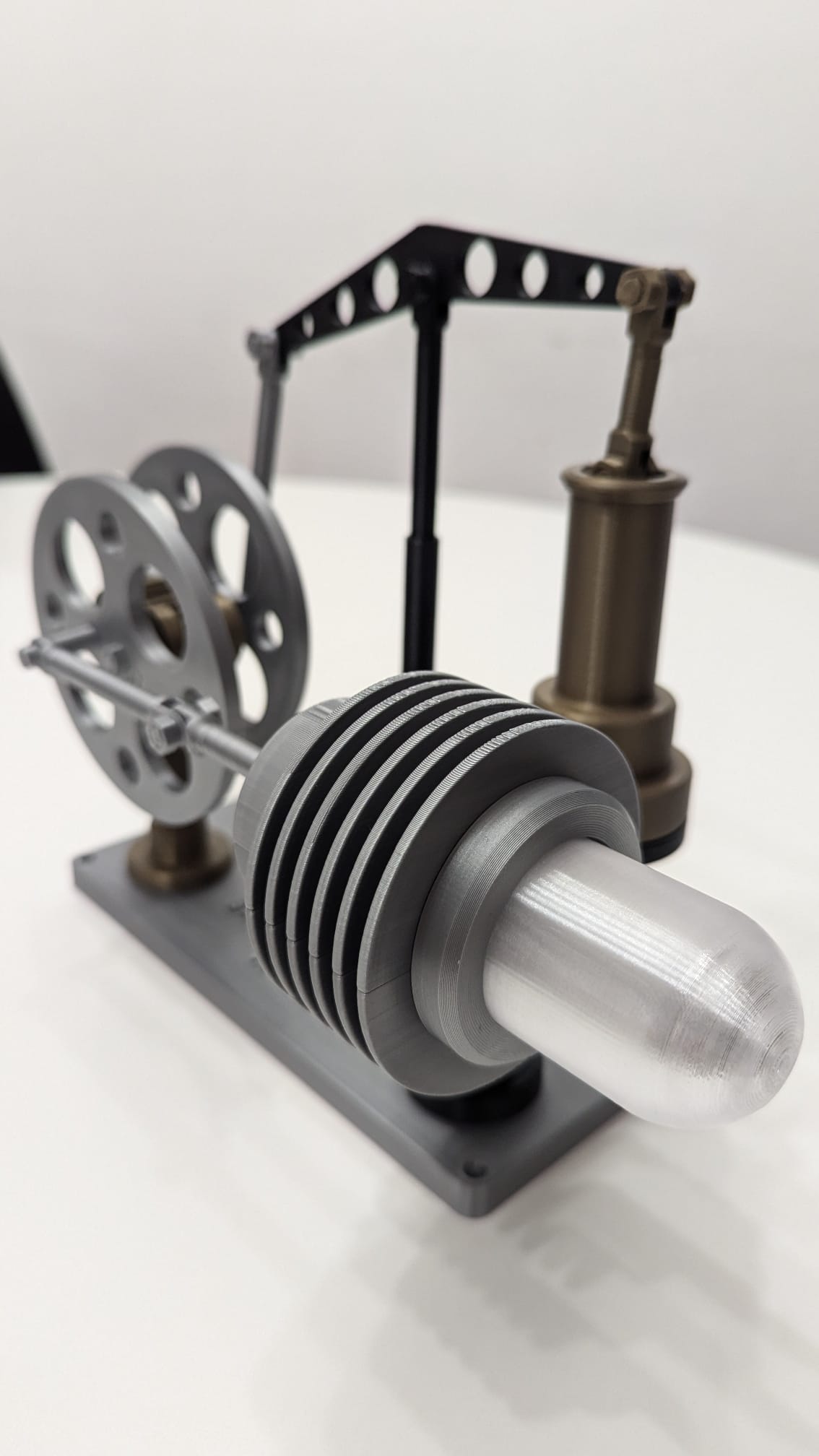
Stirling Engine – Kinematic Educational Model

Publicado em 29 de out de 2024
Gostou deste modelo? Crie uma conta grátis para salvar seus favoritos e voltar a eles depois.
Criar conta