Você está no 3DFinder
Buscamos em Thingiverse, MakerWorld e Printables ao mesmo tempo para te dar o melhor de cada uma.
Descrição
I have designed an inline six-cylinder engine with a functioning valvetrain featuring an overhead camshaft and overhead valves, with two valves per cylinder.
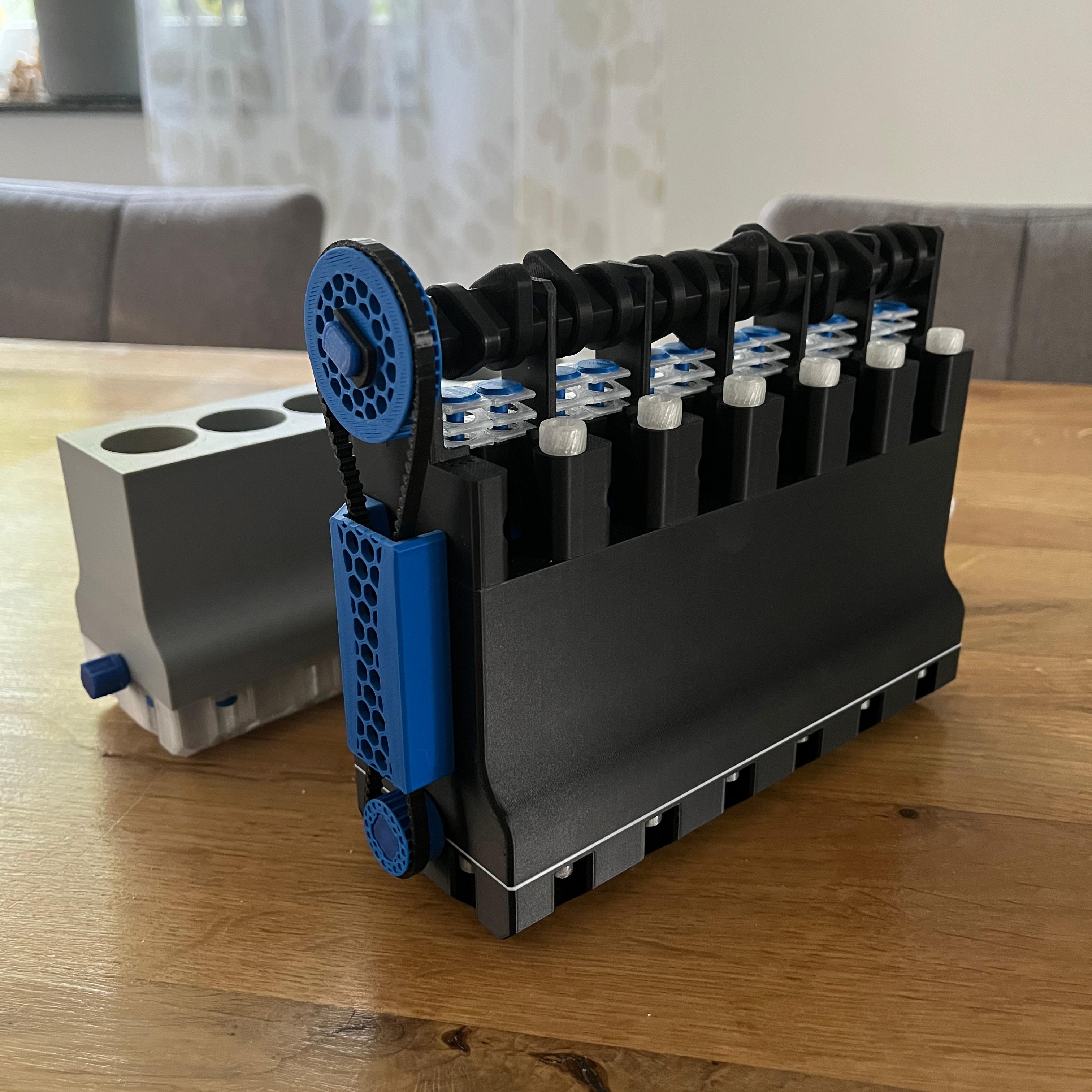
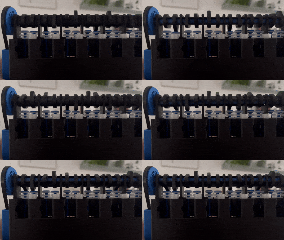
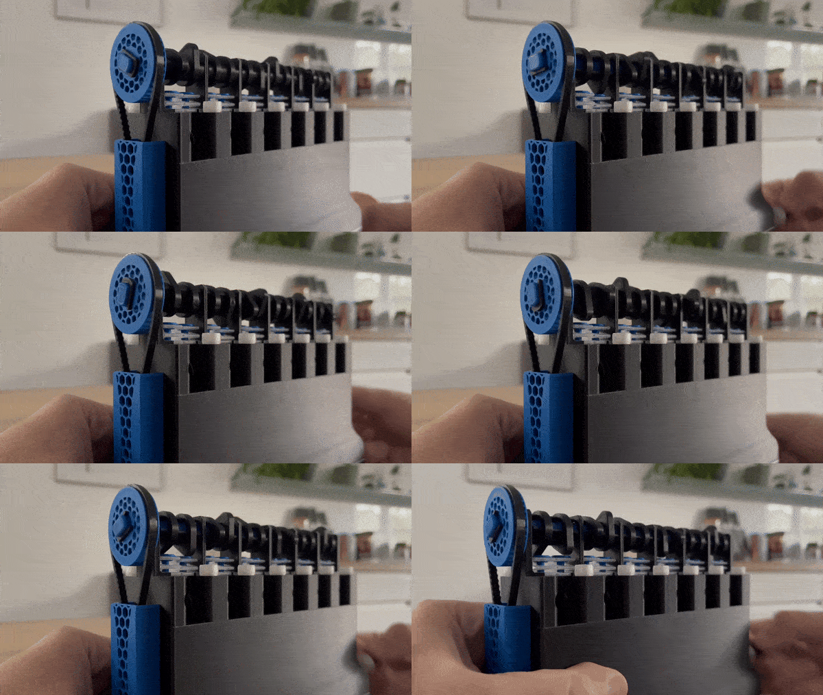
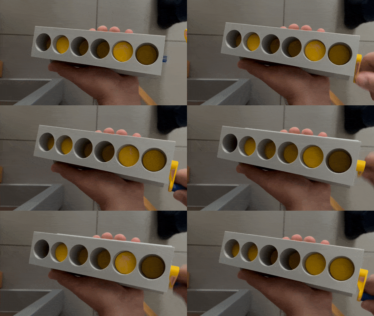
The camshaft is driven by a belt, which can be printed from TPU. All parts, including the springs and screws, are 3D printed.
The engine can also be assembled without the valvetrain. The print file includes two different engine blocks. The block without the valvetrain does not have holes for the cylinder head.
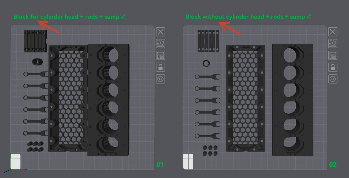
Printing Material:
I printed the engine using PLA and PETG. I recommend printing the crankshaft, camshaft, screws, and springs with PETG because the material is less brittle and has better layer adhesion than PLA. This is especially important for the screws, as they are subjected to tension when tightened. Additionally, the crankshaft and camshaft run more smoothly with PETG due to its better sliding properties.
I recommend that all components with threads (except the engine block and hand crank) be printed with a low layer height, using the variable layer height function. This is especially noticeable with the M4 screws.
Assembly:
First, the crankshaft needs to be assembled. It consists of 19 individual parts that must be put together in the order from 1 to 19. Gluing the crankshaft is not necessary, but you can do it if preferred.
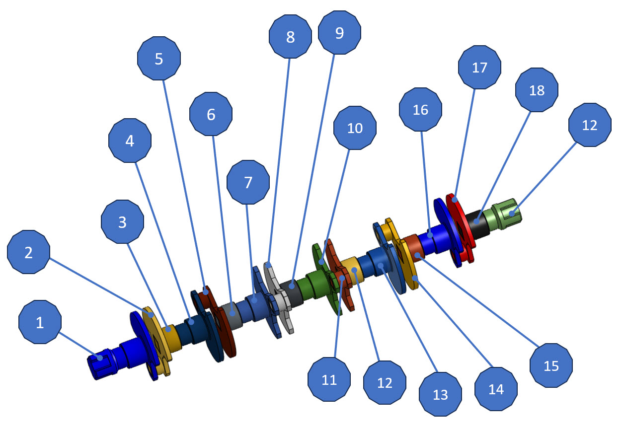
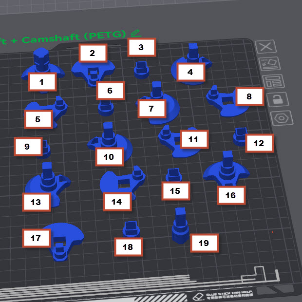
After assembling the crankshaft, it can be mounted onto the engine block. Make sure that part number 1 of the crankshaft faces forward, towards the belt side. Place the crankshaft on the bearing seats.
Next, the pistons need to be connected to the connecting rods. Simply slide the pins through the hole. The pins hold in place by friction with the pistons. Once all the pistons are connected to their rods, they need to be attached to the crankshaft. This part is a bit tricky. The pistons with the rods must be inserted from above (cylinder head side) into the cylinders, and then, with some finesse, the connecting rods need to be clicked into place on their respective crankshaft pins.
Once all the connecting rods (including the pistons) have been connected to the crankshaft, the crankshaft can now be bolted to the engine block. For this, the five bearing caps and ten M4 screws are needed. Tighten the screws by hand (without tools, if possible) until the bearing caps sit flush on the engine block. This is sufficient.
Now the oil pan (with the honeycomb pattern) can be mounted to the bottom of the engine block. Use the small M4 hex socket screws for this. Tighten them hand-tight using a tool.
If you chose the block without holes for the cylinder head, you would be finished at this point. Only the crank for the hand drive needs to be assembled. Note that the screw for the crank has a left-hand thread, so it doesn’t loosen when turning the crank clockwise.
Assembly of the Cylinder Head:
When assembling the cylinder head, the springs must be aligned correctly, and the individual parts, including the cams, must also be installed in a specific order.
Let's start with the springs, which need to be aligned as shown in the image below:
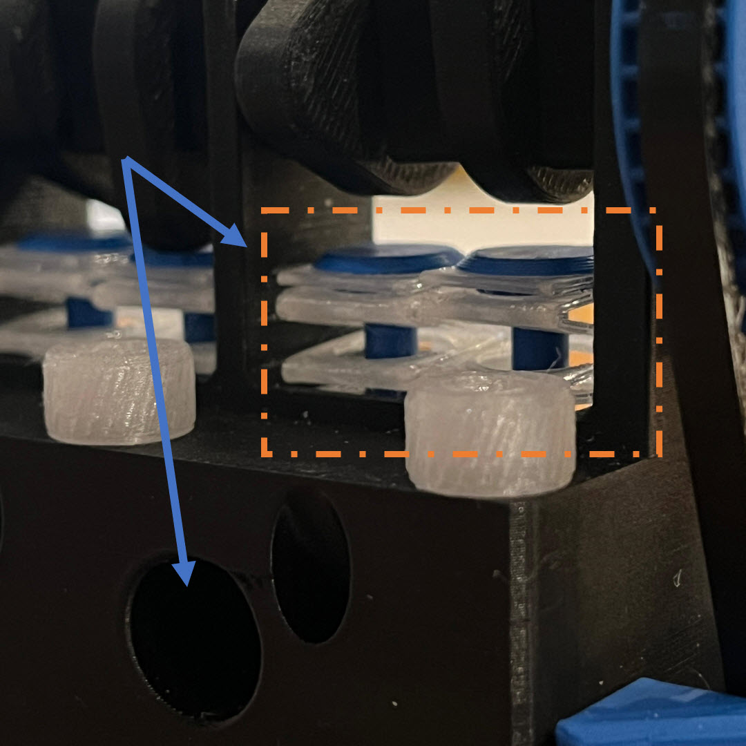
In the image, the arrows point to the engine block side where the air intake and spark plugs would theoretically be located. The other side is cut away to show how the valves operate.
Here’s the translation:
Each valve consists of two parts, a disc and the valve itself. The disc is screwed onto the valve. First, place the head on the spring, then put the spring onto the cylinder head and press it down with your finger. After that, insert the valve from the other side and screw it onto the disc.
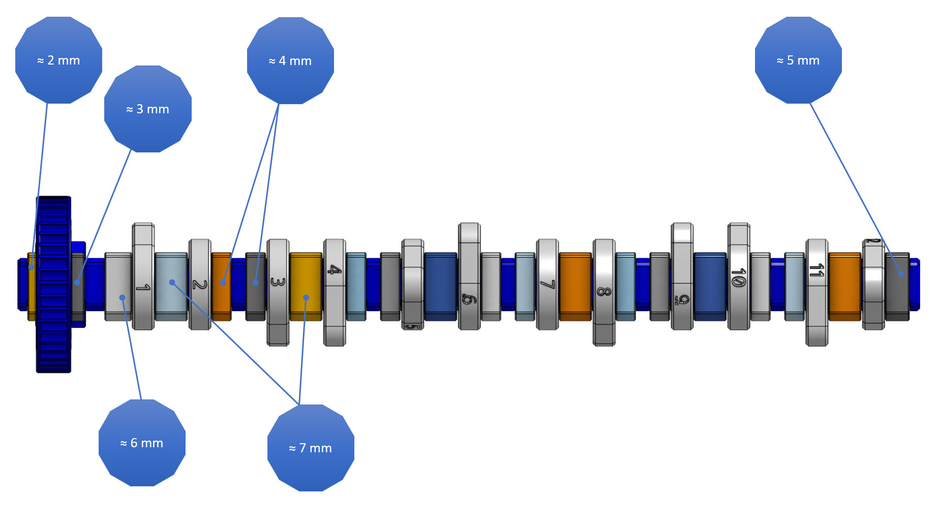
Once all the valves are installed, the camshaft can be fitted into the cylinder head. This is the most difficult part. The cams are gradually mounted onto the camshaft as it is pushed through the bore or its bearing positions. Once all the cams are mounted and the camshaft is fully inserted, the locking pins must be clicked into place to prevent the camshaft from moving axially. These act like retaining rings. They also secure the large pulley on the camshaft. The camshaft should look like this afterward:
Setting the timing:
The timing is set on the 1st cylinder, which is the cylinder closest to the pulley. The second cam is for the exhaust valve. When the cam touches the exhaust valve, the 1st cylinder should have just passed the bottom dead center and be moving upwards, theoretically expelling the exhaust gases. When the cylinder reaches the top dead center, the intake valve should start to open.
Inline 6-Cylinder Engine with optional Valvetrain

Publicado em 11 de out de 2024
Gostou deste modelo? Crie uma conta grátis para salvar seus favoritos e voltar a eles depois.
Criar conta