Você está no 3DFinder
Buscamos em Thingiverse, MakerWorld e Printables ao mesmo tempo para te dar o melhor de cada uma.
Descrição
I pulled an all-nighter to bring this project to life and I hope I’ve implemented all the technical specifications correctly in Version 1. My main sources were [https://gridfinity.xyz/specification/](https://gridfinity.xyz/specification/) and [https://www.printables.com/de/model/417152-gridfinity-specification](https://www.printables.com/de/model/417152-gridfinity-specification). If you run into any unexpected issues, feel free to reach out to me at macyo42@quantentunnel.de or drop a comment here.
BONUS |
Introduction
I would like to introduce my parametric Gridfinity model, which I developed using Onshape. I am aware that there are already many Gridfinity models available, but after printing and testing numerous designs, I noticed that many of them have issues. Either the parametrization didn’t work properly or the original Gridfinity dimensions were not accurately maintained—especially when it came to height.
My model addresses these problems by ensuring that the parametrization is precise and fully functional. Additionally, I’ve paid close attention to adhering to the original Gridfinity dimensions, ensuring that my model maintains compatibility with the system, particularly regarding height accuracy, which is often overlooked.
Moreover, I’ve added a feature that allows you to use 3D-printed labels. You have the option to choose between traditional 2D-printed labels or 3D-printed ones. If you prefer a cleaner look, you can also completely disable the labels. This flexibility ensures that the system can be customized to your personal preferences and needs.
Link to Realfinity Parametric V1 Stable Version
| I’m excited to announce that V2 Beta 2 is now available for testing! The major new feature in this version is a fully parametric box designed for the Gridfinity system. Feel free to try it out and share your feedback! Realfinity Parametric V2 Beta 2 | 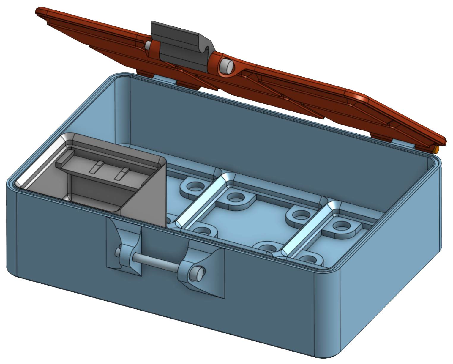 |
How-To
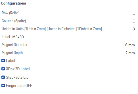
Configurations Guide for Parametric Gridfinity Model
- Row (Reihe): Set the number of rows for your model. In this example, it is set to 1.
- Column (Spalte): Set the number of columns. The example shows 1 column.
- Height in Units [1 Unit = 7mm]: Set the height in multiples of 7mm. In this case, the height is set to 3 units (21mm).
- Note: If the Stackable Lip is enabled, an additional 4.4mm is added to the total height.
- Label: Choose the type of label mounting, for example, an M3x30 label.
- Magnet Diameter: Specify the diameter of the magnet. Here it is set to 6mm.
- Magnet Depth: Define the depth of the magnet placement. In this example, the depth is 2mm.
- Label Options:
- Label: Enable or disable labels for the model.
- 3D<>2D Label: Choose between 3D-printed or 2D-printed labels.
- Stackable Lip: If enabled, the model will include a stackable lip feature, adding 4.4mm to the height for more convenient stacking.
- Fingerslide: This feature is toggled off, meaning the model will not include the fingerslide option.
By adjusting these configurations, you can fully customize your Gridfinity model to suit your needs.
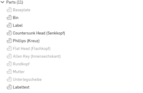
Parts Overview for Version 1 of the Parametric Gridfinity Model
In Version 1, the following parts are available to customize your Gridfinity setup:
- Baseplate:
Currently, the baseplate is only available in a 1x1 configuration, which makes it somewhat limited in functionality and not very useful in this version. - Bin:
This is the container or holder part of the model, essential for storing and organizing items. - Label:
The label can be customized with additional elements or printed as a blank label if preferred. Starting from the label, you can combine different parts to customize the look of your labels.- Important Note: If you choose to deactivate the label or opt for a 2D-printed label, these customizable combinations of symbols (e.g., Phillips, Countersunk Head, etc.) will not exist. The label will either be absent or follow the 2D printed format without the option for these detailed customizations.
- Customizable Label Components:
- Countersunk Head (Senkkopf): A label element featuring a countersunk head.
- Phillips (Kreuz): A label with a cross-head screw design.
- Flat Head (Flachkopf): A flat-head screw design for labels.
- Allen Key (Innensechskant): A label featuring an Allen key design.
- Rundkopf: A round-head screw label.
- Mutter: A nut symbol that can be added to the label.
- Unterlegscheibe: A washer symbol for labels.
- Labeltext: Custom text that can be added to the label.
Usage Guide
- Label Customization:
You can choose to combine these parts (e.g., Phillips, Countersunk Head, etc.) with your label to create a custom look. Each of these parts represents a different icon or symbol that will appear on the label. - Blank Labels:
If desired, you can also print a label without any symbols or text. Simply select the label part and leave the additional components out for a clean, blank label. - Label Deactivated or 2D Option:
If you deactivate the label feature or select a 2D-printed label, the customizable label components (like the screw symbols and icons) will not be part of the design.
This flexibility allows you to fully customize your labels according to your needs, whether you want detailed symbols, a minimalist blank label, or a simple 2D-printed design.
Export

Exporting Parts Guide
The red-highlighted symbol in the image is the Export button, which allows you to export selected parts from your project. Here's a brief guide on how to use it:
- Exporting Selected Parts:
If you have already selected the parts you want to export, simply click on this Export button. This will initiate the export process for the selected parts. - Selecting Parts for Export:
- If you haven't selected any parts yet, click on the Dropdown Arrow next to the export icon.
- From the dropdown menu, choose "Select and Export."
- You will then be able to select the specific parts you want to export. Once selected, the export will proceed.
This functionality helps streamline the export process, ensuring you have control over which parts to include in the export.
Export Tip:When exporting, always export together as one STEP file only the parts you intend to print as a single part. For example, do not export the Bin and a 3D Label in the same STEP file.
If you load a STEP file with multiple parts into Bambu Studio, the individual parts will appear as separate objects, which you can then color individually. This makes customization and visualization much easier. |
Export Dialog Guide
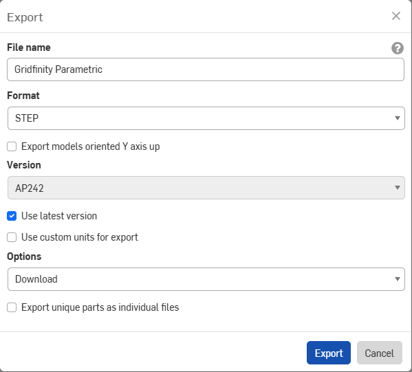
This image shows the Export Dialog window, which allows you to export your project. Here's a guide on the important steps:
- File Name:
- The most important field in this dialog is the File name field. You should choose your desired file name at this point.
- If you don’t set the name here, you will have another opportunity to do so in the next step when saving the file.
- Format:
- It is highly recommended to select the STEP format. This format is widely compatible and commonly used for exporting 3D models.
- Other Options (Optional):
- Export models oriented Y axis up: Not generally important unless specific axis orientation is required for your project.
- Version: This can typically be left as is, with the default option (e.g., AP242).
- Use latest version: This option ensures the latest version of your project is being exported, which is typically what you want.
- Options: Leave this on Download unless you have a different export method in mind.
- Export unique parts as individual files: Leave unchecked unless you need each part exported as a separate file.
- Final Step:
- After configuring your file name and format, click the Export button to proceed with the export process.
By focusing on the File Name and Format fields, you ensure the correct naming and file type for your project while other settings can remain at their default values.
Credits
I decided not to create this project in OpenSCAD because, despite my efforts, I found it impossible to build the necessary skills within a reasonable time frame. I spent several hours trying to get something functional in OpenSCAD, but I just couldn’t achieve the results I wanted. While using OpenSCAD would have allowed direct customization here on Makerworld, I ultimately had to choose a different approach to get the job done.
I also have to say that I absolutely love Onshape. In over 25 years of using various CAD tools, I’ve never found one as enjoyable as Onshape. It allows me to realize everything I need, and it’s easier to use than any other tool I’ve tried. Plus, the fact that it all works directly in the browser is just incredible. While OpenSCAD would have been convenient for direct customization here on Makerworld, Onshape has made the entire process much more efficient and enjoyable for me.
Gridfinity Parametric (Onshape) correct dimensions

Publicado em 20 de ago de 2024
Gostou deste modelo? Crie uma conta grátis para salvar seus favoritos e voltar a eles depois.
Criar conta