Você está no 3DFinder
Buscamos em Thingiverse, MakerWorld e Printables ao mesmo tempo para te dar o melhor de cada uma.
Descrição
HELLO MAKERWORLD!
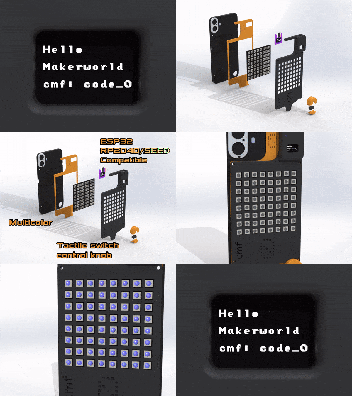
This is code_0, an attachment mod for the CMF phone 1.
Surely the nothing phone series might have a glyph interface…
but now the cmf phone has a full 8x8 rgb matrix display!
The attachment is compatible with all super mini esp32-c3 boards and rp2040, in addition also mini seeduino boards with xtensa processors fit in the package. Meaning that you are carrying with you not only the controller of the matrix display, but also powerful pentesting boards!
Provided there are ALL STEP files, as indeed you can completely personalize this project to make it your own!
PS:
If you really want to, nothing is stopping you from printing the original STEP case file (provided by nothing) and the files included in the project all together to have not a mod but a full case! Consider that i have used an esp32-c3 by 01-space with an embedded lcd screen, so there is a small window for you to modify, eliminate, or just add a small piece of paper with a smile :)
But before continuing further…
DISCLAIMER: IF YOU KNOW NOTHING ABOUT ELECTRONICS, PLEASE FOLLOW AT LEAST BASIC COURSE BEFORE PROCEEDING.
LEDs generates HEAT which, if not dealt with correctly, can be dangerous! I do not take responsibility if you don't know what you are doing.
This is a beautiful DIY project that requires skill and attention to details.
Remember to use the display at low brightnesses!
The mod consists of these 3d printed parts:
- Sticker part: the colored part that separates the boards from the phone case. The provided part is 2mm thick + extruded screw holes depth. BUT if you have very thin wires, you can actually modify the STEP files provided to make it thin as you like. In my case, i used it 1mm thick.
- Housing part: the black part that can be considered the main part.
- (optional) Controller knob: the part that can be mounted by removing the accessory screw of the nothing phone.
- (optional) USB C Ribbon cable for using the 5W reverse charge capability of the CMF phone 1 to power up the system, instead of using the main cable port.
Plus you'll need:
- 1x 8X8 RGB ws2812 (66x66mm) or similar panel that works with the adafruit library
- 1x ESP32c3 super mini with an integrated 0.41" LCD display (the one from 01-Space) or other compatible boards and/or displays.
- Some cables (go thin ONLY if you know what you are doing).
- Some heat-shrinking cable tubes.
- Double sided tape for electronics or/and heat resistant sponge for locking in place the electronics component inside the housing and attach the sticker part to the main housing.
- 4x round headed M2.5 screws for the housing attachments. Please calculate the necessary length accordingly to your sticker height (consider the base sticker included model is at 2mm + 2mm of the necessary screw hole spacers + the main housing height is 3mm) so for the base model you'll need 4x AAXXX screws.
- (optional) 1x AA078 4mm length M2.5 cone headed screw for the control knob
- (optional) 1x D2F-L endstop switch for the control knob
There is not much to say about the wiring diagram, the display has (please check your display input requirements) to be connected to the 5V and Ground pin of your board. Up to you to decide which pin you want to use to connect the led data pin! In my case i used the Arduino IO pin 7 (I programmed everything in arduino IDE).
I, unfortunately, don't own a usb-c ribbon L shaped cable, but i've left a large enough cut in the housing so you can put one there to stop using external power banks! The CMF Phone has a 5W reverse charging capability, i couldn't test that but it should work. The usb-c should be connected directly to the 5V and GND pins of the ESP32, i don't know for other boards unfortunately.
Regarding the matrix display, Adafruit Libraries are full of examples with all the possible led effects, and they can be easily loaded onto the esp32 and triggered with a control button, that is why i created the control knob.
I wanted to create a “digital encoder” knob, but i found out it would've been a project on it's own given the complexity.
BUT an easier possibility would've been using a 7x7x5mm rocker switch. Bonus for you I've added the STEP and 3MF files for this particular rocker switch:
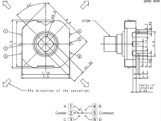
And if you are good enough of a pcb designer, you could design an SMD PCB to add in the specific rocker control knob.
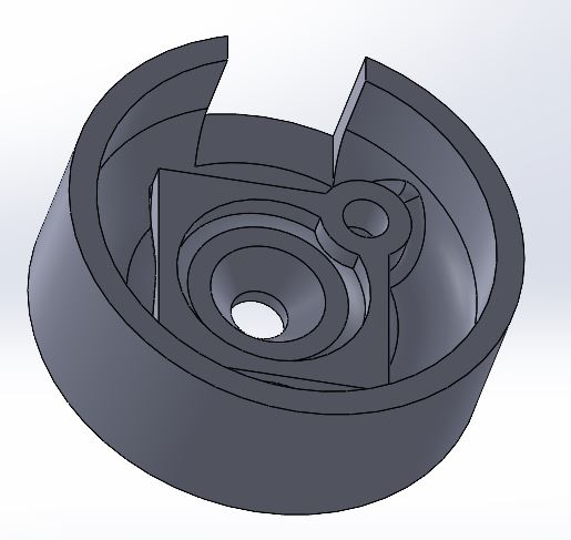
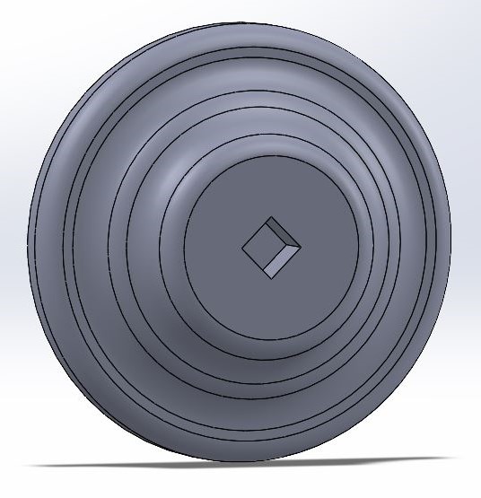
In my case, as i didn't have this rocker switch, i decided to use beautiful endstop switches, that work like a charm:
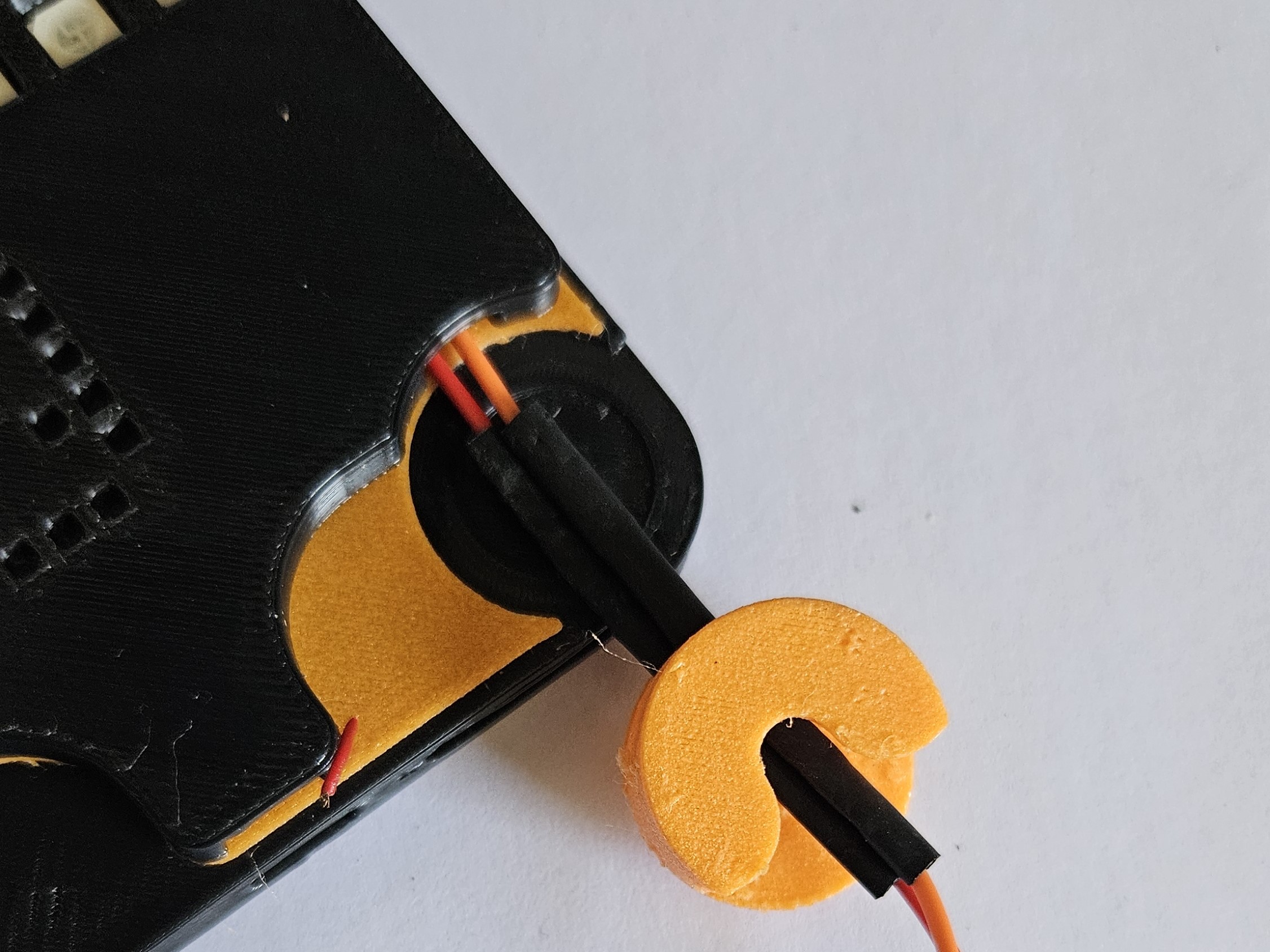
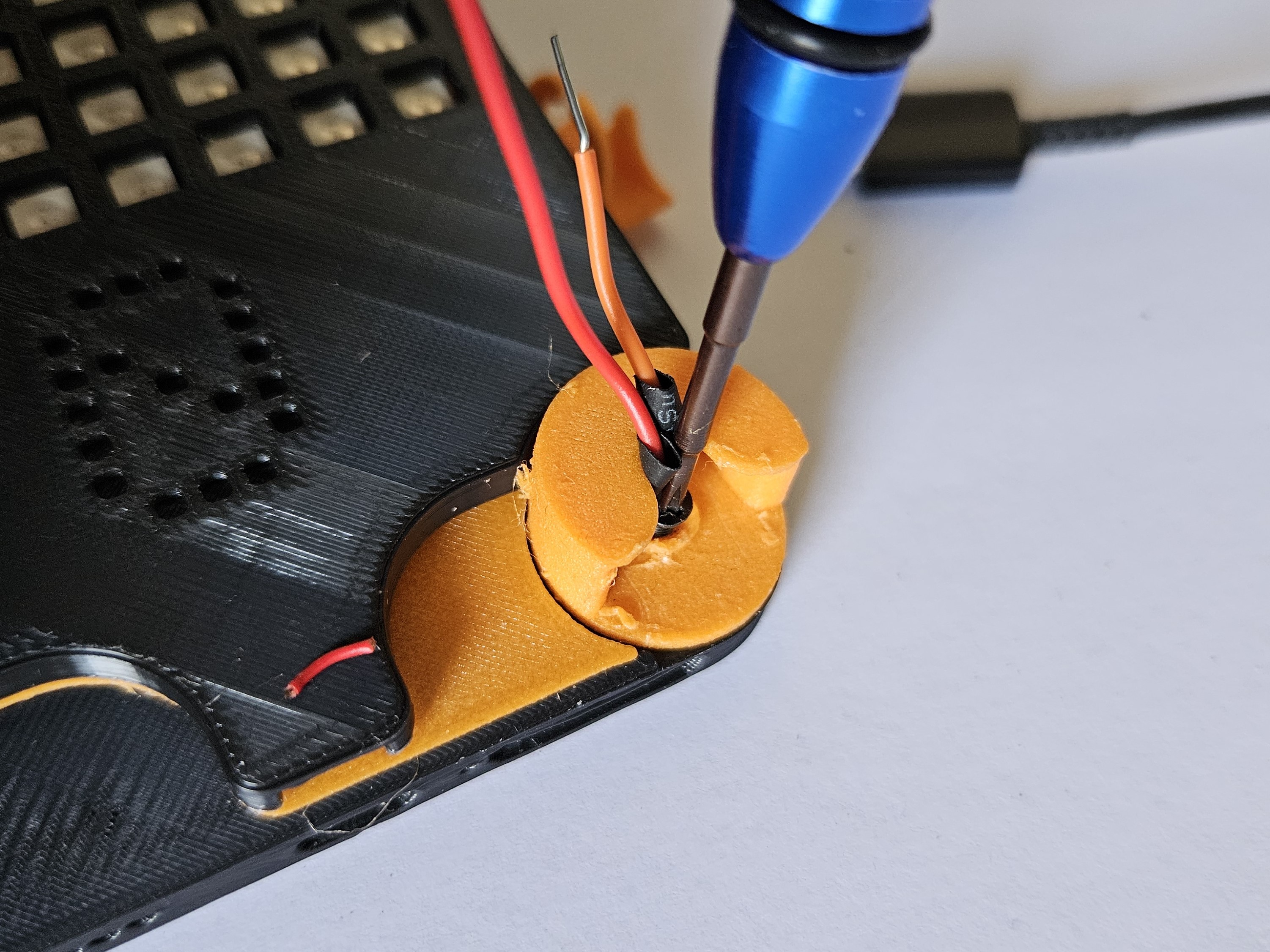
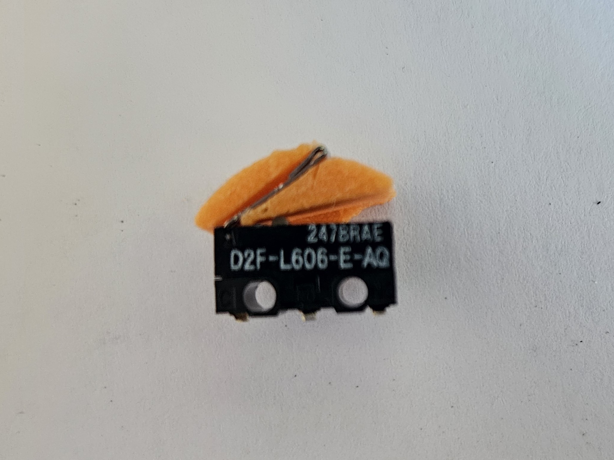
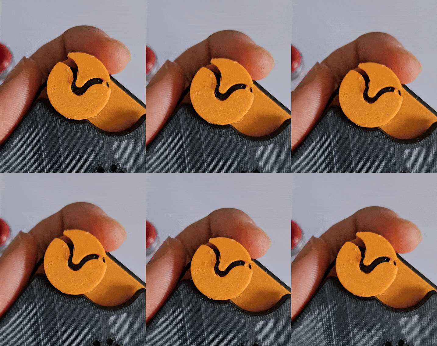
But still, the control knob is in an ALPHA STAGE, so i encourage you to share your ideas and your models for further iterations of the control knob!
Also, that is why i wrote optional, as ESP and Wifi boards don't need actual physical controls, you just need to connnect to them!
If you don't have an endstop switch, i tried my best modelling a “buttonhole” mechanism design that should work “universally” with whatever switch the knob fits, given you block it with a wide enough washer (printed or not it makes no difference).
For the pentesting, if the project goes well I'm up to supporting it, maybe with some github repos, some tamagochi-like interactions (absolutely no reference to flipper, ahem, zero so far) or by following updates here on makerworld, but for the moment it's been 5 hard days of all day work to have a good model and rendered images to share.
But I ensure you there are many projects out there with already VERY good builds!
I hope you'll have fun making your CMF phone a beautiful party-light disco machine and a powerful tool for your days to come! Share, improve and remix this project as you like.
Have fun! And if you like the project:
Code_0 - Matrix display and pentesting mod for CMF

Publicado em 6 de ago de 2024
Gostou deste modelo? Crie uma conta grátis para salvar seus favoritos e voltar a eles depois.
Criar conta