Você está no 3DFinder
Buscamos em Thingiverse, MakerWorld e Printables ao mesmo tempo para te dar o melhor de cada uma.
Descrição
DIY Sim Racing Button Box
Like many sim racing enthusiasts, I wanted a button box that would fit perfectly into my own setup without taking up too much space. This project was designed around that idea: creating something practical, clean, and enjoyable to use during every race.
The button box features 21 buttons and 3 rotary encoders, providing plenty of inputs for all the functions you need at your fingertips.
To give the finished build a more realistic motorsport feel, I printed the parts using a Carbon Fiber Textured Plate. The textured surface adds a premium look that blends naturally with most sim racing rigs and gaming setups.
This is not intended to be a professional-grade racing product—it's simply a project made by a new sim racer for fellow sim racers who enjoy building, customizing, and improving their own setups. If you're looking for a functional and good-looking DIY addition to your cockpit, I hope this design will be a great starting point.
Wanna see it in motion? Check my Instagram Post.
Enjoy the build, and good luck on track! 🏁🏎️
Materials I´ve used
| Item | Amount | Where I bought it |
| 16mm Momentary Push Buttons | 16 | Aliexpress |
| KY-040 Rotary Encoders (360°) with knob caps | 3 | Aliexpress |
| Toggle Switches with protective cover | 1 | Aliexpress |
| 2-Pin Screw Terminal Blocks | 10 | Local Store |
| BAV21 Rectifier Diodes | 30 | Local Store |
| Perfboard / Prototype PCB 47 × 72 mm (371 holes) | 2 | Local Store |
| M3 Brass Heat-Set Inserts (M3x5x4 mm) | 20 | Aliexpress |
| Arduino Micro Pro - USB C | 1 | Aliexpress |
Electrical diagram
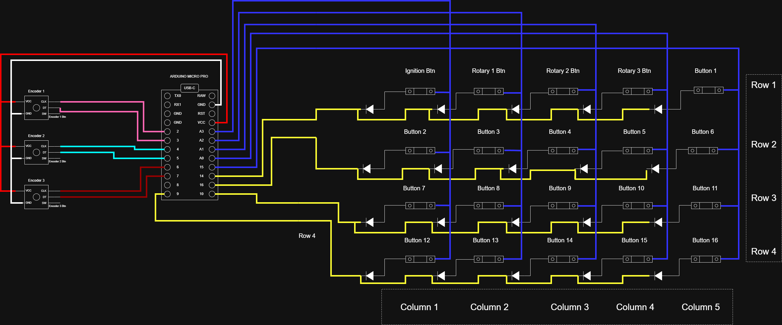
Arduino Code
´´´C
// ================== CONFIG ==================
// #define HALF_STEP // encoders half-step
//#define ENABLE_PULLUPS // encoders with no internal pull-up
#include <Joystick.h>
constexpr int NUMROTARIES = 3;
constexpr int NUMROWS = 4;
constexpr int NUMCOLS = 5;
constexpr int NUMBUTTONS = 20;
byte rowPins[NUMROWS] = {9, 10, 16, 14};
byte colPins[NUMCOLS] = {15, 18, 19, 20, 21};
bool buttonState[NUMBUTTONS] = {0};
// ================== JOYSTICK ==================
Joystick_ Joystick(
JOYSTICK_DEFAULT_REPORT_ID,
JOYSTICK_TYPE_JOYSTICK,
32, 0,
false, false, false, false, false, false,
false, false, false, false, false
);
// ================== ENCODERS ==================
struct RotaryEncoder {
byte pin1;
byte pin2;
int ccwchar;
int cwchar;
volatile unsigned char state;
};
RotaryEncoder rotaries[NUMROTARIES] = {
{2, 3, 20, 21, 0},
{4, 5, 22, 23, 0},
{6, 7, 24, 25, 0},
};
constexpr uint8_t DIR_CCW = 0x10;
constexpr uint8_t DIR_CW = 0x20;
constexpr uint8_t R_START = 0x0;
#ifdef HALF_STEP
constexpr uint8_t R_CCW_BEGIN = 0x1;
constexpr uint8_t R_CW_BEGIN = 0x2;
constexpr uint8_t R_START_M = 0x3;
constexpr uint8_t R_CW_BEGIN_M = 0x4;
constexpr uint8_t R_CCW_BEGIN_M = 0x5;
const unsigned char ttable[6][4] = {
{R_START_M, R_CW_BEGIN, R_CCW_BEGIN, R_START},
{R_START_M | DIR_CCW, R_START, R_CCW_BEGIN, R_START},
{R_START_M | DIR_CW, R_CW_BEGIN, R_START, R_START},
{R_START_M, R_CCW_BEGIN_M, R_CW_BEGIN_M, R_START},
{R_START_M, R_START_M, R_CW_BEGIN_M, R_START | DIR_CW},
{R_START_M, R_CCW_BEGIN_M, R_START_M, R_START | DIR_CCW},
};
#else
constexpr uint8_t R_CW_BEGIN = 0x2;
constexpr uint8_t R_CW_FINAL = 0x1;
constexpr uint8_t R_CW_NEXT = 0x3;
constexpr uint8_t R_CCW_BEGIN = 0x4;
constexpr uint8_t R_CCW_FINAL = 0x5;
constexpr uint8_t R_CCW_NEXT = 0x6;
const unsigned char ttable[7][4] = {
{R_START, R_CW_BEGIN, R_CCW_BEGIN, R_START},
{R_CW_NEXT, R_START, R_CW_FINAL, R_START | DIR_CW},
{R_CW_NEXT, R_CW_BEGIN, R_START, R_START},
{R_CW_NEXT, R_CW_BEGIN, R_CW_FINAL, R_START},
{R_CCW_NEXT, R_START, R_CCW_BEGIN, R_START},
{R_CCW_NEXT, R_CCW_FINAL, R_START, R_START | DIR_CCW},
{R_CCW_NEXT, R_CCW_FINAL, R_CCW_BEGIN, R_START},
};
#endif
// ================== Methods ==================
void initEncoders() {
for (int i = 0; i < NUMROTARIES; i++) {
pinMode(rotaries[i].pin1, INPUT);
pinMode(rotaries[i].pin2, INPUT);
#ifdef ENABLE_PULLUPS
digitalWrite(rotaries[i].pin1, HIGH);
digitalWrite(rotaries[i].pin2, HIGH);
#endif
}
}
void checkAllEncoders(void) {
for (int i = 0; i < NUMROTARIES; i++) {
unsigned char result = processEncoder(i);
if (result == DIR_CCW) {
Joystick.setButton(rotaries[i].ccwchar, 1);
delay(50);
Joystick.setButton(rotaries[i].ccwchar, 0);
};
if (result == DIR_CW) {
Joystick.setButton(rotaries[i].cwchar, 1);
delay(50);
Joystick.setButton(rotaries[i].cwchar, 0);
};
}
}
unsigned char processEncoder(int i) {
unsigned char pinstate = (digitalRead(rotaries[i].pin2) << 1) | digitalRead(rotaries[i].pin1);
rotaries[i].state = ttable[rotaries[i].state & 0xf][pinstate];
return (rotaries[i].state & 0x30);
}
// ================== Button Matrix ==================
void scanButtons() {
for (int c = 0; c < NUMCOLS; c++) {
pinMode(colPins[c], INPUT_PULLUP);
}
// varrer linhas
for (int r = 0; r < NUMROWS; r++) {
pinMode(rowPins[r], OUTPUT);
digitalWrite(rowPins[r], LOW);
for (int c = 0; c < NUMCOLS; c++) {
int index = r * NUMCOLS + c;
if (index >= NUMBUTTONS) continue;
bool pressed = (digitalRead(colPins[c]) == LOW);
if (pressed != buttonState[index]) {
buttonState[index] = pressed;
Joystick.setButton(index, pressed);
}
}
pinMode(rowPins[r], INPUT);
}
}
// ================== SETUP / LOOP ==================
void setup() {
Joystick.begin();
initEncoders();
for (int r = 0; r < NUMROWS; r++) {
pinMode(rowPins[r], INPUT);
}
}
void loop() {
scanButtons();
checkAllEncoders();
}
´´´
Notes and Assembly Tips
I used two breadboards to make the wiring connections, but they are not strictly necessary. The components can be wired directly together using wires routed behind the enclosure lid. I originally chose the breadboards to keep everything organized, but in the end it actually became more confusing because of the large number of wires required to connect the terminal blocks and the Arduino.
Installing the Heat-Set Inserts
For the best results, I recommend heating the threaded inserts with a soldering iron set to approximately 180°C. Gently press the insert into the hole, then use a flat object to push it the rest of the way in until it sits flush. This helps ensure the inserts go in straight and cleanly.
Testing the Buttons
To verify that all buttons are working correctly:
- Press Win + R.
- Type joy.cpl and press Enter.
- Select the Arduino controller from the list.
- Press the buttons and verify that they register correctly in the test window.
Gostou deste modelo? Crie uma conta grátis para salvar seus favoritos e voltar a eles depois.
Criar conta