Você está no 3DFinder
Buscamos em Thingiverse, MakerWorld e Printables ao mesmo tempo para te dar o melhor de cada uma.
Descrição
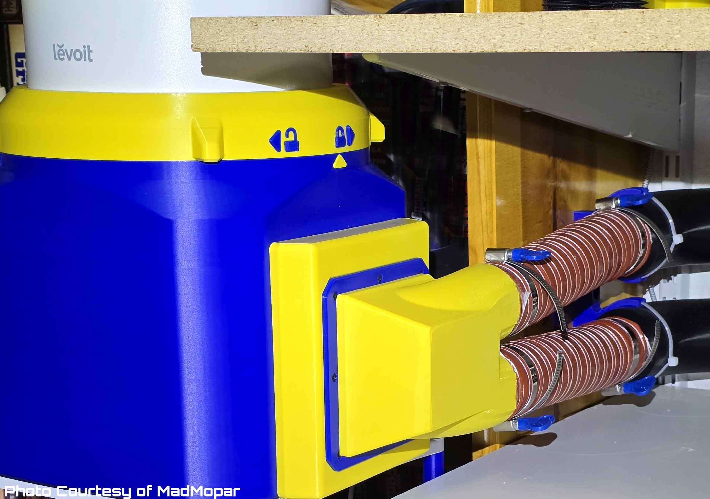
The idea for this design was suggested by MadMopar, since he wanted to use the "Perfect Poor Man's Filter" by MrFunctionalPrint, but it would not fit on a P1 without using a split model. I really liked the idea of a similar design, but sized for a smaller printer, so I put together the design, and he tested it (since I do not own a Levoit Core 200S filter). While this design is similar in concept to the"Perfect Poor Man's Filter", it is not a remix and uses none of the parts from that design. While making this design only cost me some spare time over several weeks, the prototype designs were tested at MadMopar's expense of several spools of filament, a few discarded prototypes, and hours of assembly and feedback to improve the design. The design is finally at the point where it's been in operation in his setup, and functionally tested, so I feel we can release it. This has not been tested scientifically however, so if you have the equipment to do that please post your results. Without the initial suggestion, and assistance from MadMopar, it would not have been possible to share this take on a Levoit Core 200S based 3D printer design with the community, so a big thanks goes out to him!
 |  |  |
I also have to say this is a make it (and use it) at your own risk project, so please keep that in mind before you decide to make or use this. I do not have hard data to know how well this design will work to clean the exhaust air from our 3D printers. I have also not personally tested the configuration (since I do not own a Levoit Core 200S filter), and so far there is only one system in use. This is a use of the Levoit Core 200S filter which will probably void your warranty, and is not a use case the manufacturer would have envisioned. So keep that in mind when deciding if you should make use of this design. If you do make one, please monitor it to verify it is working as you intend, and post a comment on your experince, and if you feel there is a way to improve the design. No warranties are given.
Due to the number of different ways to build this filter, not all of the ducts which are available for it have been tested, however the key mechanical elements of them have been tested. That is not to say that I don't have confidence that the ducts will work, since I've gone over the designs many times and feel they are good. If you make one of these and use it, please provide feedback to improve the design further. This is released under a license which allows for remixing, so feel free to improve the design or add any additional ducts you need. I've got a few more optional carbon filters and additional 2.5" ducts designed, but I need further help to test them before they will get posted. If you are interested in testing any of those, please post in the comments.
The risk factors for this design (that I can think of) include possible stress on the Levoit Core 200S due to a more constrained airflow, and air flow problems related to restrictions in the piping or hoses which connect the filter to a printer, as well as cleaning performance with ABS/ASA printing exhaust. To make the most of the filter, I recommend keeping the hoses as short as possible, and using the largest diameter hoses you can. I don't recommend using this design when there is going to be a restriction to the airflow from the printer due to long hose runs, or restrictions in the exhaust flow from the printer.
This design was tested in a single configuration with two printers connected using 2" ABS piping and hoses (which totaled around 7'), and with exhaust fans on the printers also running. In that setup there was sufficient air flow. A 2" (inside diameter) hose is the minimum I think this would work well with (but use your judgement based on your setup and needs). Using any filter with ABS is challenging, so I strongly recommend using a Bento Box style recirculating filter, and then venting outside if it's possible. A previously used Levoit filter was installed in the Core 200S used for testing this design, and it helped with smells from running ABS, but it's unknown how long the OEM filter will keep up with the VOC loads from 3D printing. Additional carbon inserts for printers running ABS or ASA may be needed to better remove the odors and extend the OEM filter life. I've designed additional carbon inserts, and we've tested one of them so far (which was too restrictive using carbon flakes). But I have an improved carbon insert design which is untested (and unreleased), so if you are interested in trying it, PM me or post a comment. There are also some untested 2.5" hose ducts, but those cannot be uploaded here until they are tested (but they are available over on Printables (https://www.printables.com/model/1754424-25-ducts-for-bambu-p2s-and-p1-exhaust-see-descript).
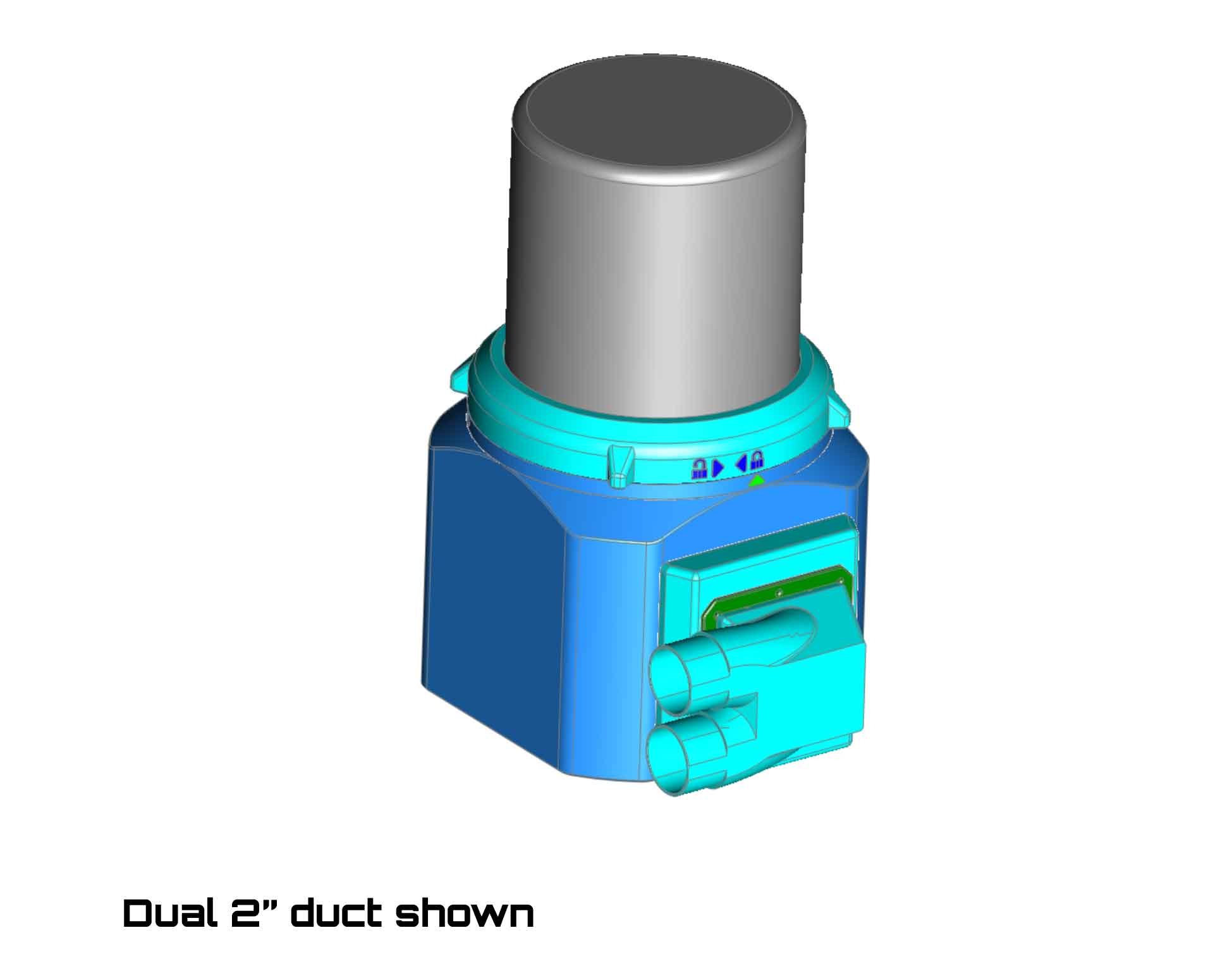
With all that said, the design is a "can" base, which fits over the base of the Levoit Core 200S filter. There is a "lid" which attaches the "can" base to the filter, using some 5/16" foam weather stripping tape. This is a similar configuration that's used in the “Perfect Poor Man's Printer / VOC Fume Extractor”, which inspired the design originally. The design here is somewhat modular, with a bolt on front section and a cover plate that can accommodate different hose ducts. Currently only the 2" hose mounts (in a separate profile) are included here. Those ducts use 16x 10x3 cylinder magnets to attach. There are also options to add TPU "gaskets" between some of the parts. I have several 2.5" duct profiles which are untested, and will not be posted here until they are (so please PM me if you are interested in testing them out).
Included in the profile are four versions of the "can" parts, with the only difference being the location of the power cord hole.
IMPORTANT, PLEASE READ:
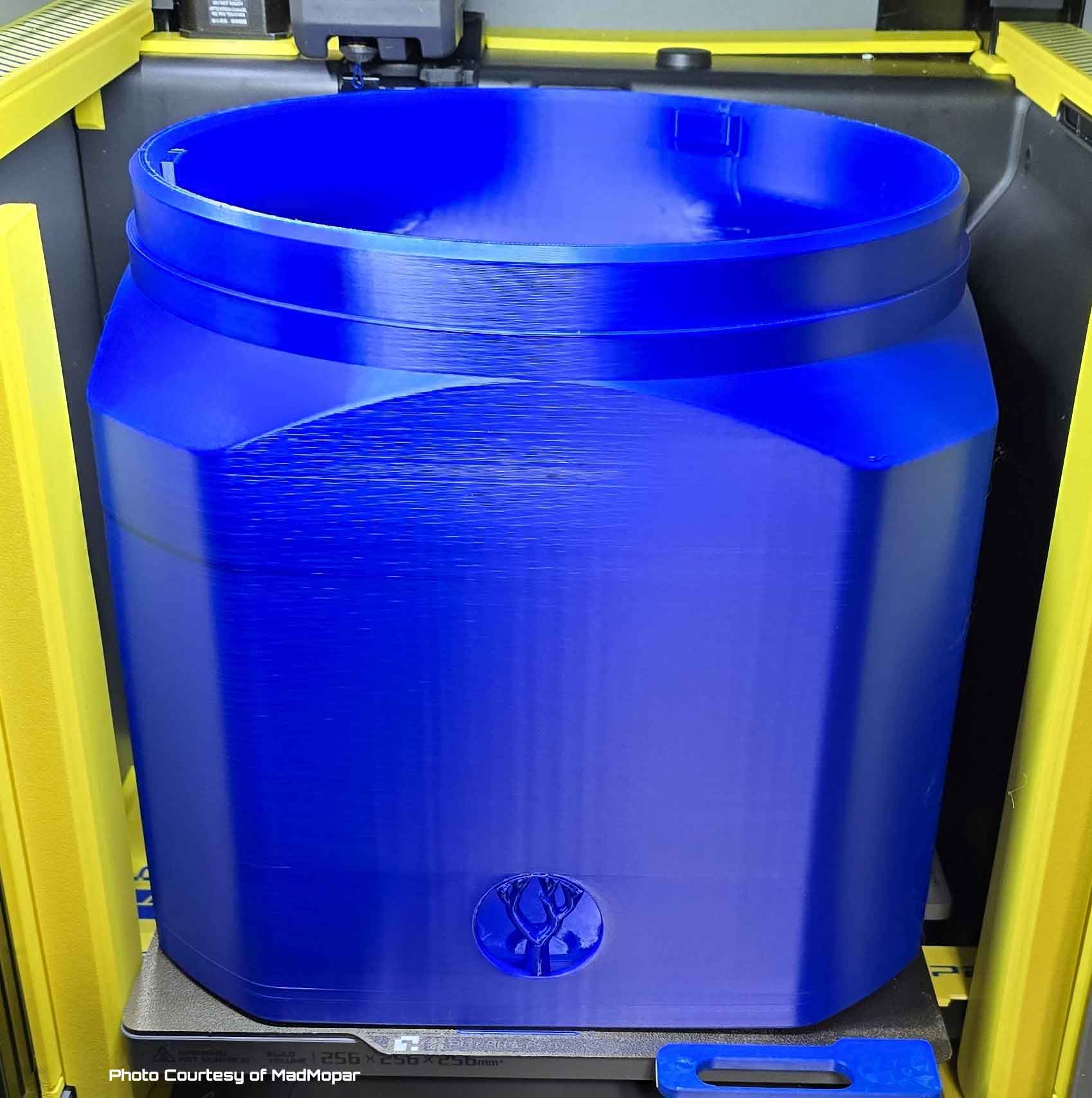
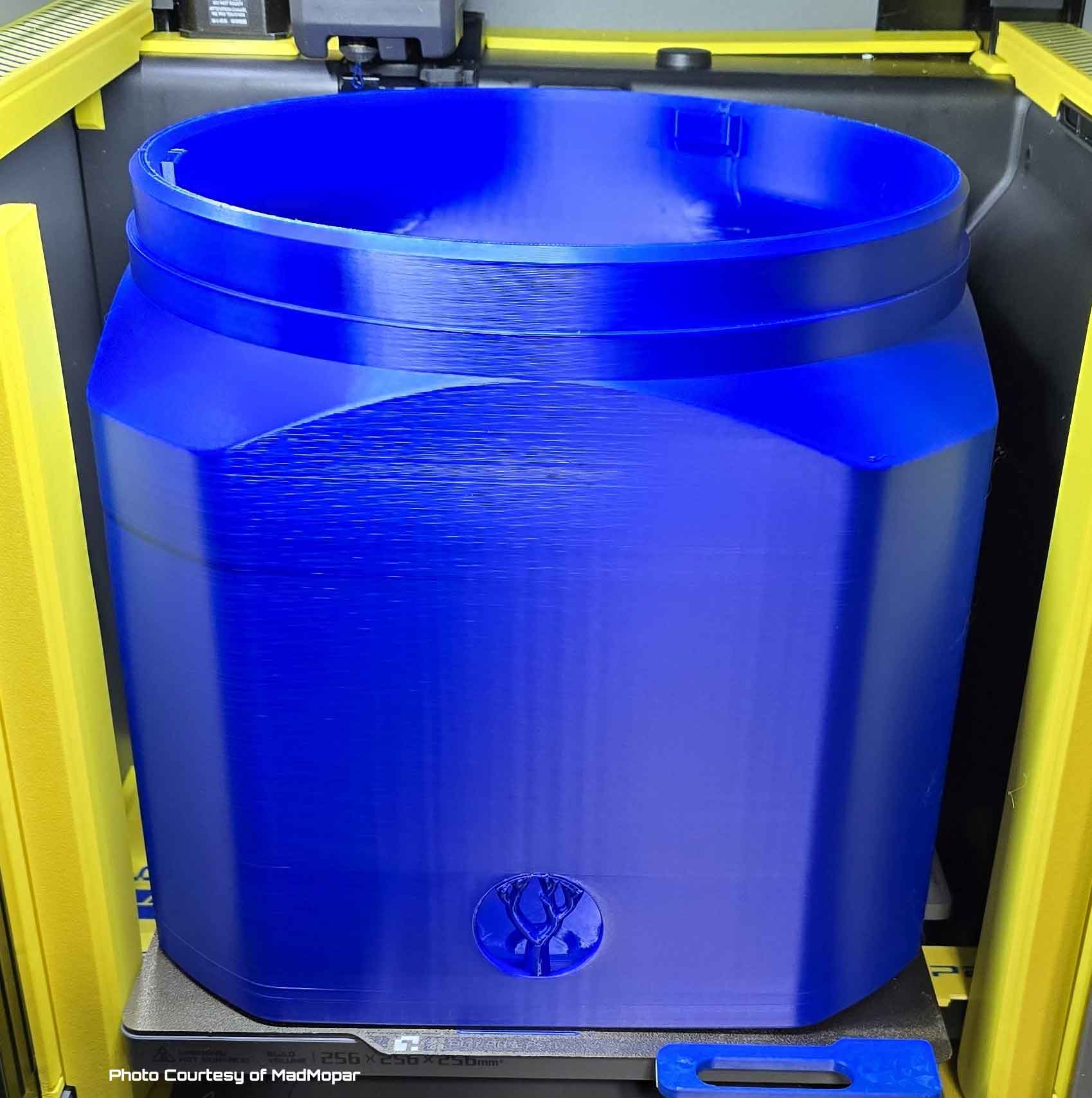
The included profile is set up for a P2S. But if you plan to print this on an X1 or P1 printer, you will need to utilize the full build area to print the "can". This includes the area which is normally reserved for the cutter actuation on multicolor prints on the X1 and P1. Therefore the included profile will not automatically slice on an X1 or P1, until the changes to use the full build area are made in the slicer and on the printer. To use the full build area on an X1 or P1 requires printing a block to move the cutter trigger out of the way, and making a small configuration change in the slicer. Bambu has documented these changes for the X1 and P1 in the wiki below:
[https://wiki.bambulab.com/en/knowledge-sharing/print-volume-limitations](https://wiki.bambulab.com/en/knowledge-sharing/print-volume-limitations)
Due to the number of parts and different ducts, I've decided to split things up into profiles.
The main profile (has most of the parts needed to build the design EXCEPT for the ducts and related parts):
“Main Profile without ducts”
Levoit Core 200S 3D_Printer_Filter_v6Z.3mf
A profile with magnetically attached 2" ducts (and the associated cover plates):
“2” Magnetically Attached Ducts and Cover Plates"
Levoit Core 200S 3D_Printer_Filter_v6X_2in_Ducts_and_Front_Insert.3mf
Also available over on Printables is an untested 2.5" magnetically attached duct. I have other unpublished 2.5" duct designs which are not magnetically attached as well, but those are also not tested.
PENDING TESTING - A profile with magnetically attached 2.5" ducts (and the associated cover plates):
“2.5" Magnetically Attached Ducts and Cover Plates"
Levoit Core 200S 3D_Printer_Filter_v6Z_2-5in_Ducts_and_Front_Insert.3mf
There may be additional profiles added for any new duct sizes which are designed, as well as the additional carbon filter inserts, which are not yet tested (so PM me if you are interested in helping to test the 2.5" ducts or the carbon filter inserts).
Below is an image of the plates in the “Main Profile without ducts”:
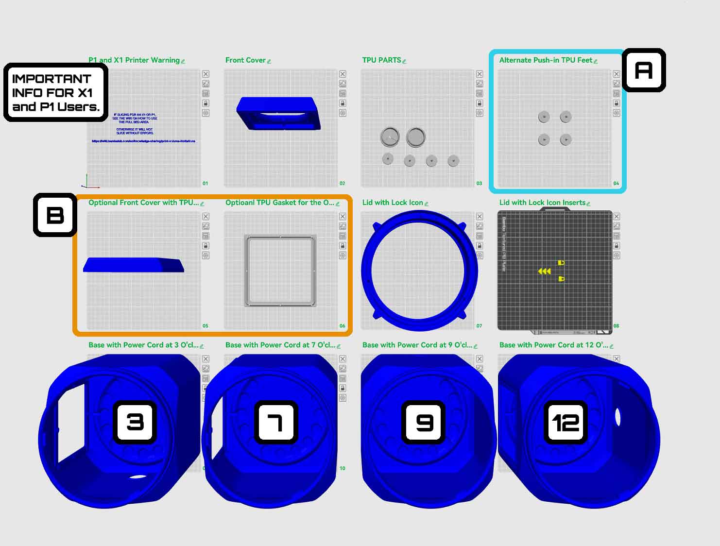
In the image above:
- The first plate has important info for X1 and P1 users, see above for more details.
- The blue box with an “A” are some alternate TPU feet (plate 4), which may be more secure than the basic feet included on plate 3. The feet on plate 4 have a ridge which may help secure them, though they still should be glued in as well.
- The orange box circling plates 5 and 6 with a “B” are the plates needed if you want to use a TPU gasket between the “can” and the front cover". If you use the parts from plates 5 and 6 you do not need to print plate 2. There is also a front cover plate, which has a TPU gasket option, however that is not shown here, since the cover plates will be included in the duct specific profiles.
- The bottom row shows the “cans”, which are the same, aside from the location of the hole for the power cable. From left to right, they have the power cable hole at 3, 7, 9 and 12 o'clock, relative to the large opening which is at 6 o'clock.
The build guide below should cover the assembly, but if you have questions, post a comment.
Build Guide:
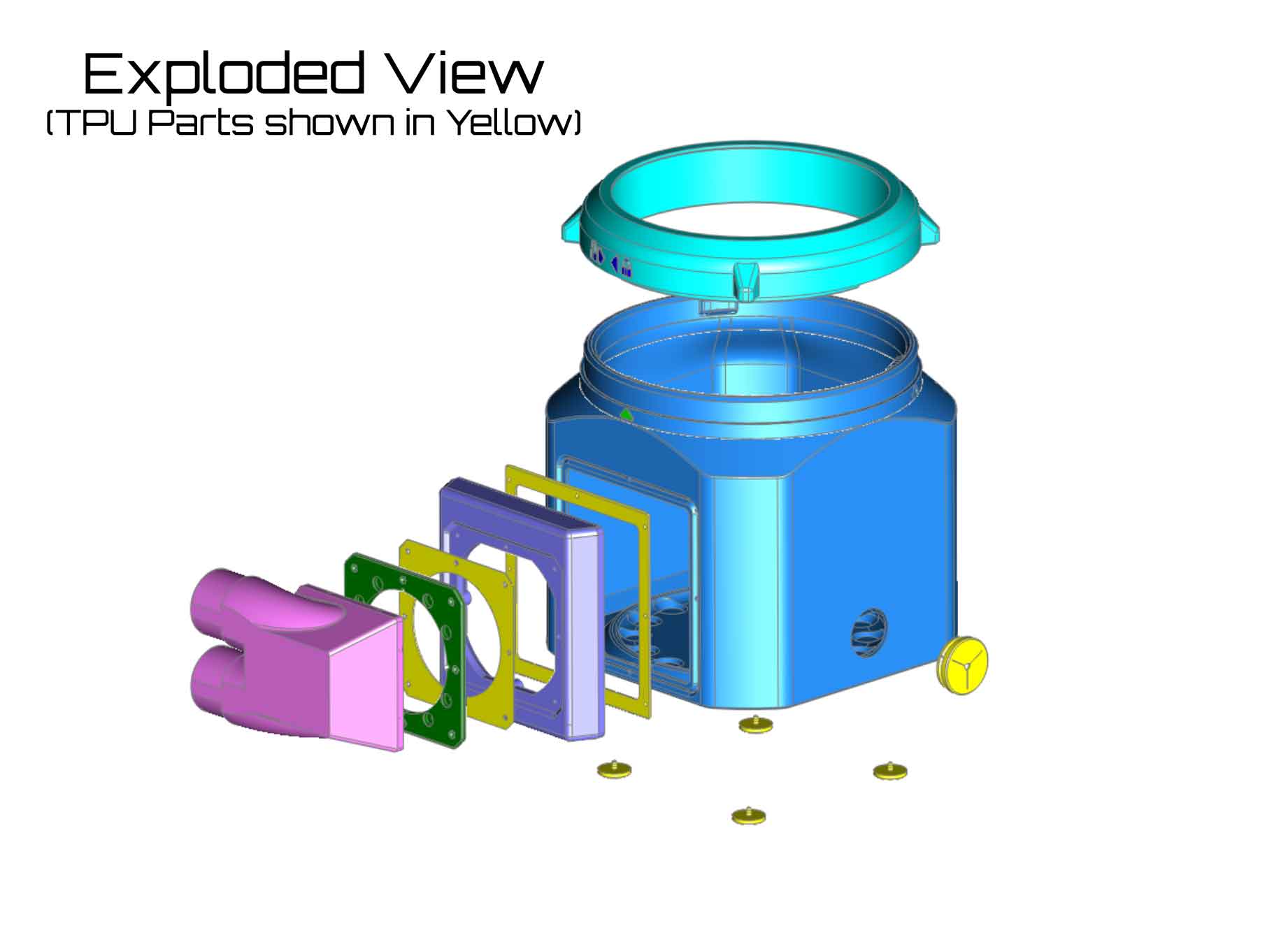
In the above image, note that the TPU parts are shown in yellow. The TPU square gaskets are optional, and require different front cover and front cover plate inserts, which are included with the profiles.
This design requires the following hardware:
- 16x M3x16mm FHCS
- 16x M3 Locknuts
- 16x 10x3 cylinder magnets
- Less than a yard of 5/16" foam weatherstripping tape (Frost King R538H Foam Tape or similar)
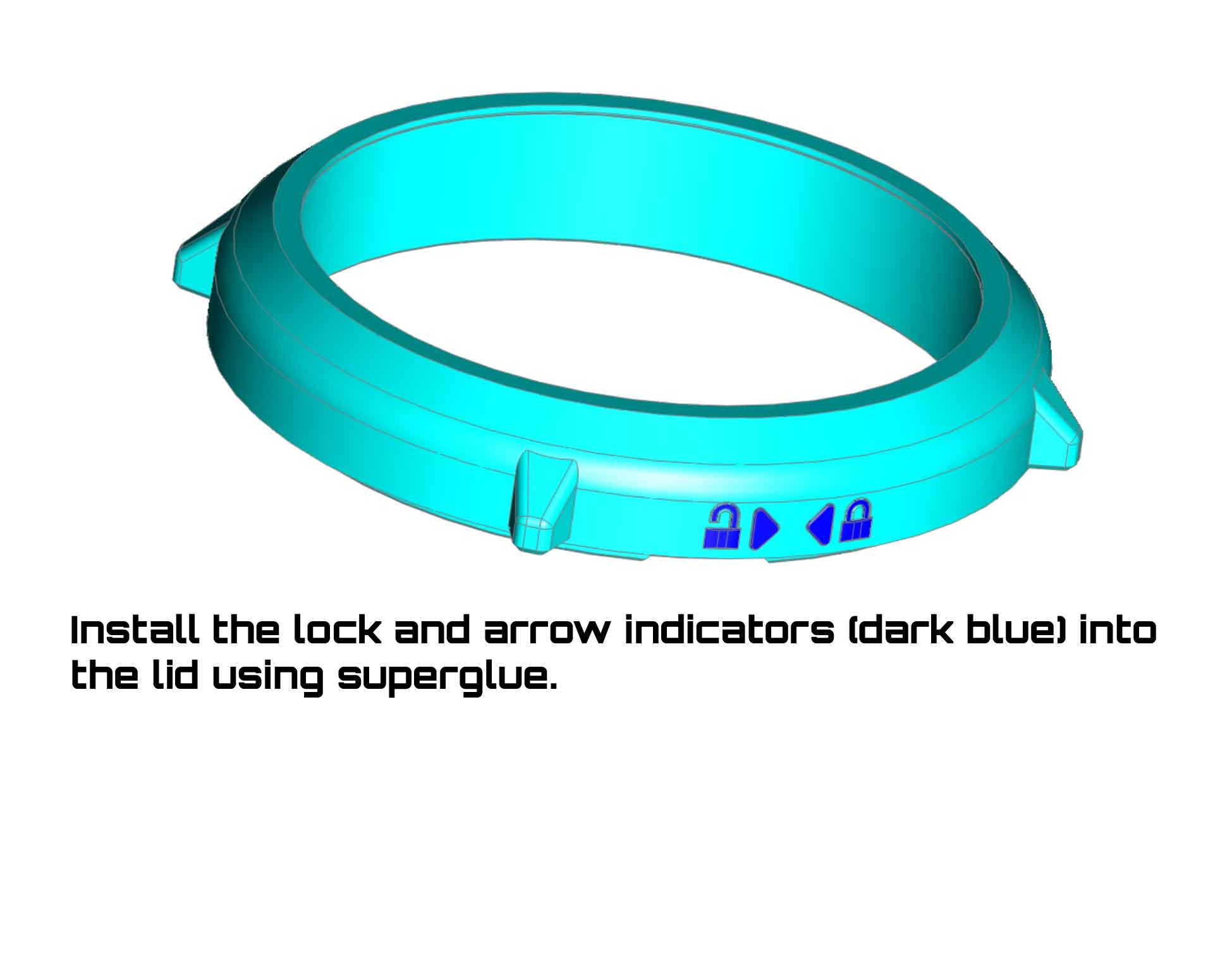
- Superglue for the feet, magnets and lock icon inserts
- Hose clamps or zip ties will be needed for the hose adapters as well.
There are a couple things to note first, regarding these instructions:
- Although most of the parts are going to be available in the “Main Profile without ducts”, some of the parts shown in the instructions below will only be found in the duct specific profiles.
- Due to MakerWorld rules there is currently only 2" ducts available here, which use 10x3 magnets to attach. There are several 2.5" ducts which have been designed, but are not tested (so please PM me if you would like to test them and provide pics and feedback to allow them to be posted).
- There is an option to add TPU gaskets between the “can” and the front panel (which carries the M3 locknuts). If you choose to use the TPU gaskets, the parts required for the front panel and front panel insert will be different, so be sure to print the correct ones. If you are not sure, ask in the comments.
Step 1: Install the 5/16" thick weather stripping in the lid.
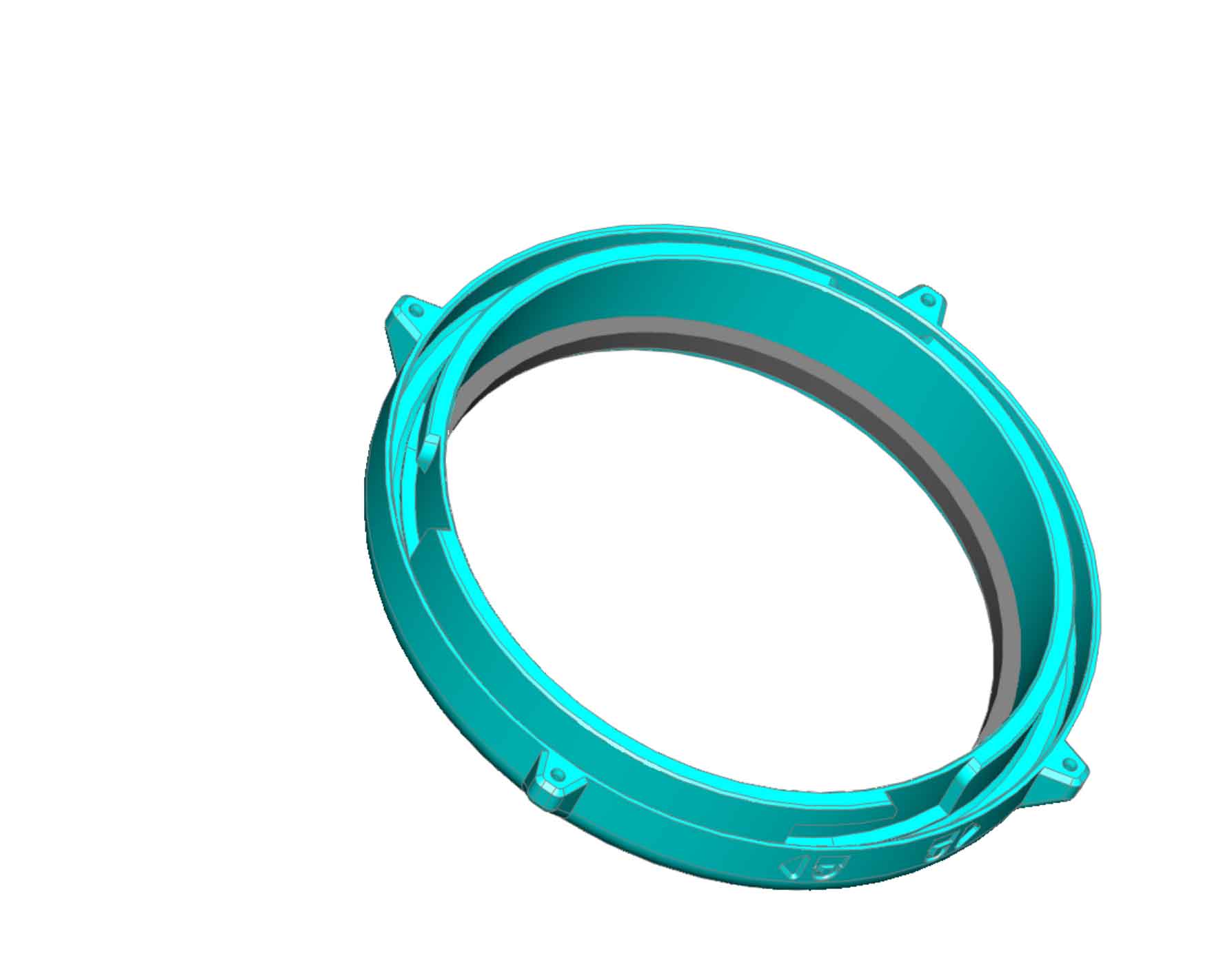
Step 2: Install the icon inserts into the lid and "can" using superglue.
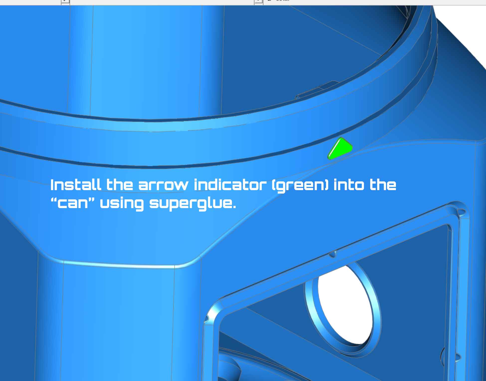 |  |
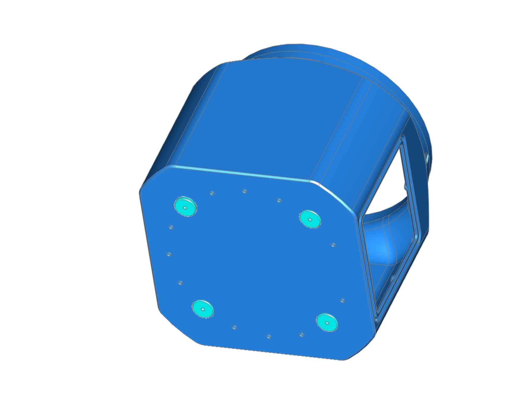
Step 3: Install the TPU feet in the base "can" using superglue. The pic shows four feet installed, however you can use as many feet as you need. If you find that the default feet on plate 3 are loose, there is an “alternate” set of feet included with the main profile (on plate 4), which should fit tighter. For both types of feet, I recommend using superglue to secure them.
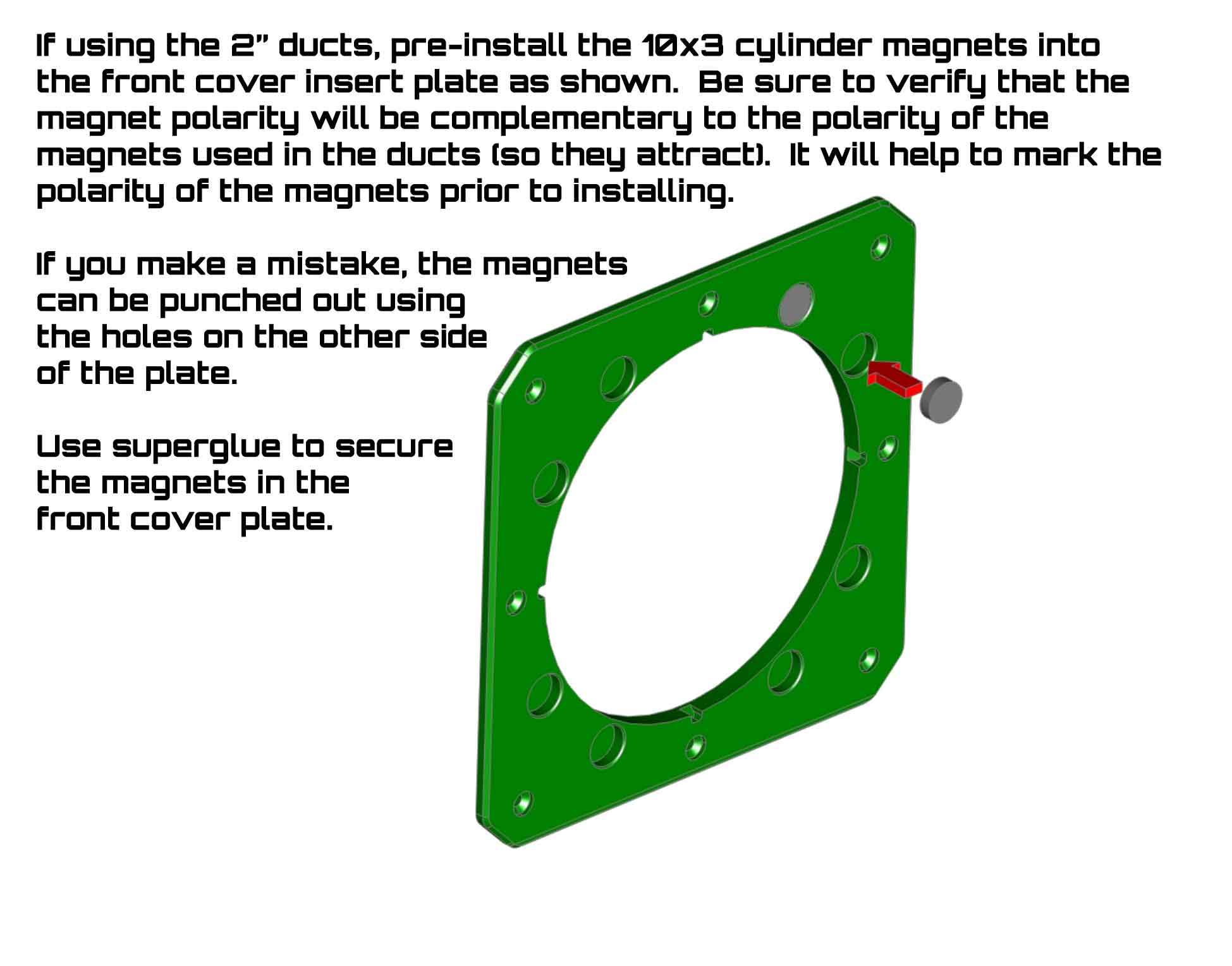
Step 4: Mark the polarity on the 10x3 cylinder magnets, so the pole direction can be verified during assembly. Insert the 10x3 cylinder magnets into the magnet duct front cover plate as shown in the image. I recommend keeping the polarity of the magnets going in the same direction, which will make things simpler. If the magnets are installed incorrectly, they can be pushed out though the hole in the back of the cover. The part shown in the image is available in the profile for the 2" magnetically attached ducts (it is not in the main profile).
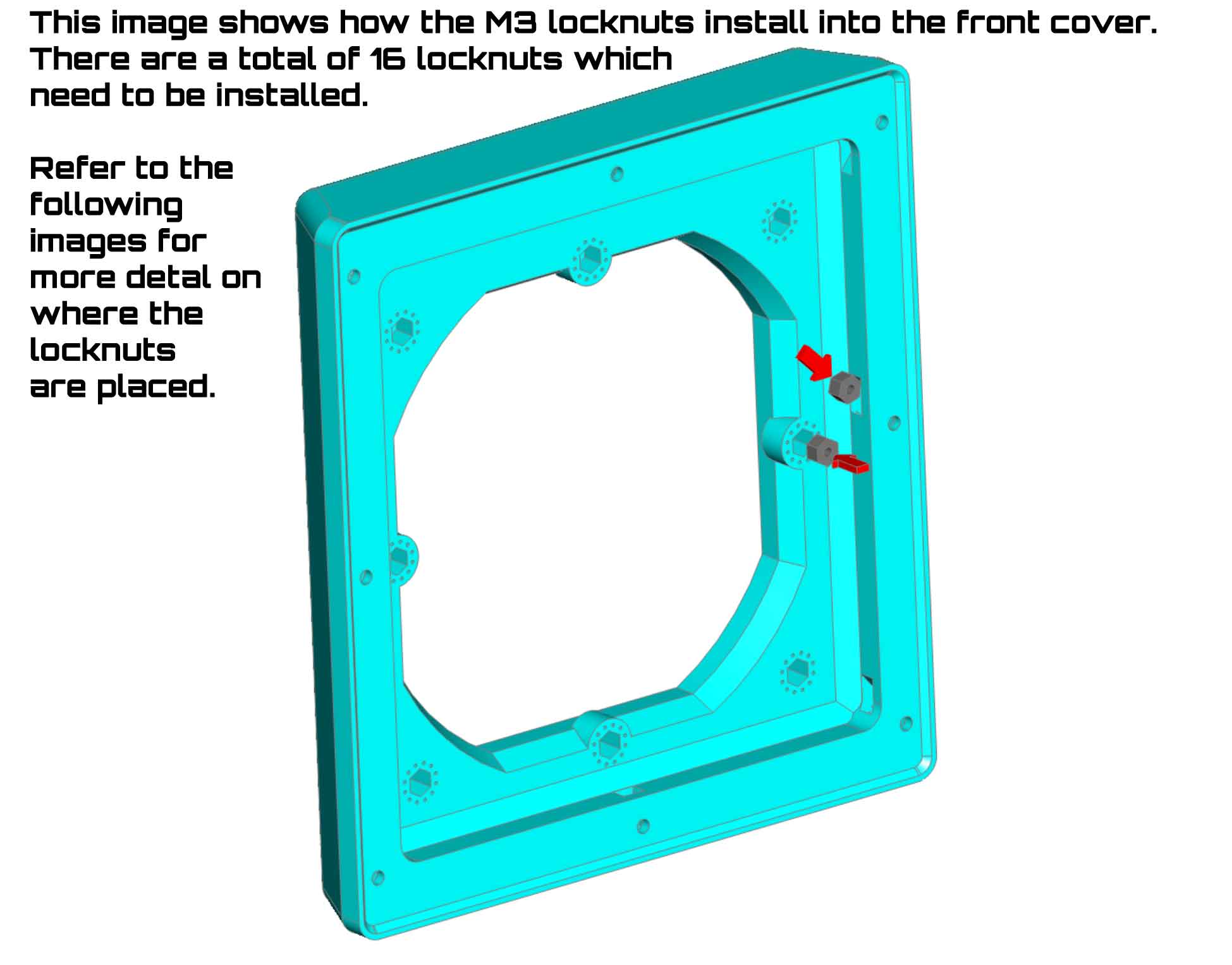
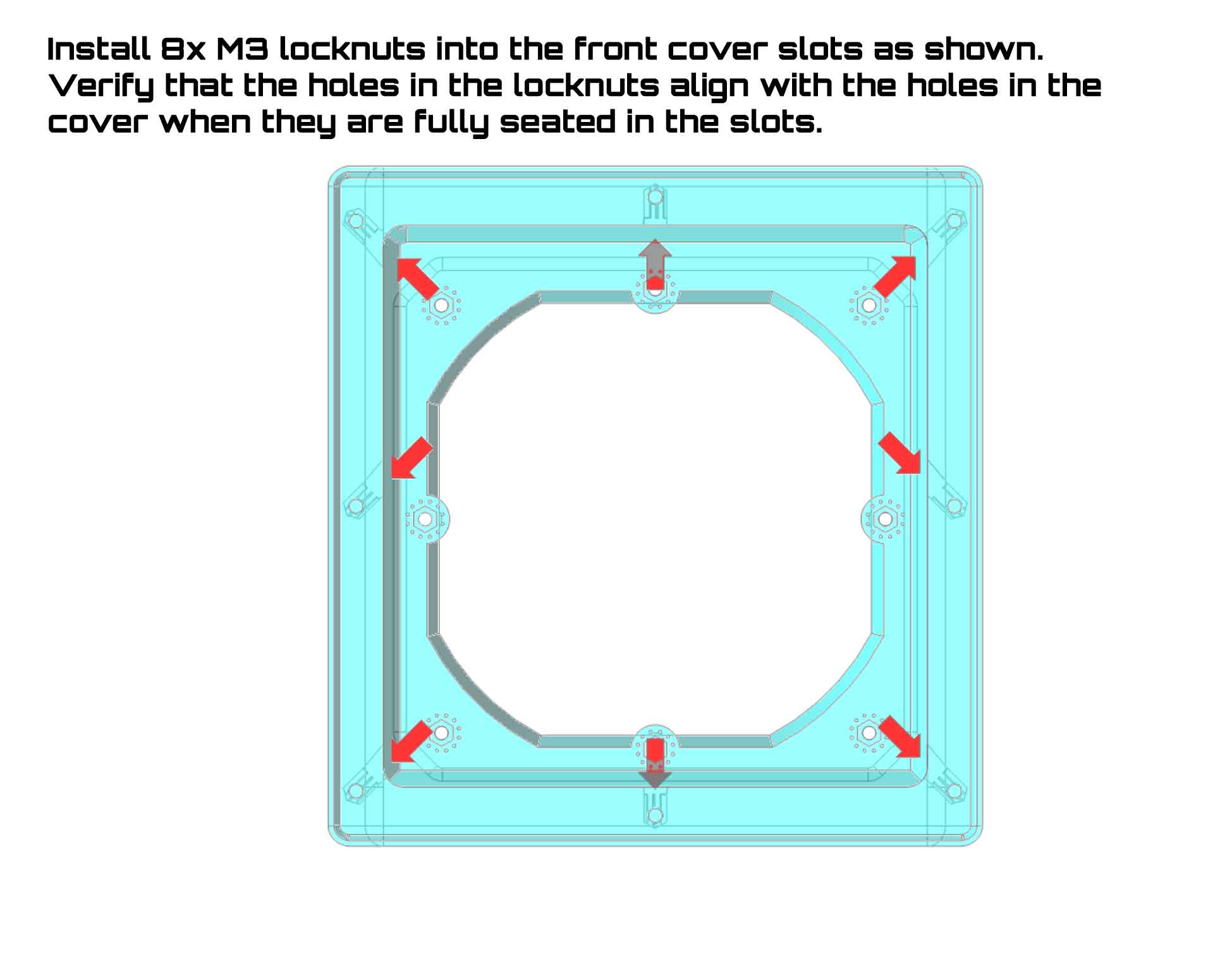
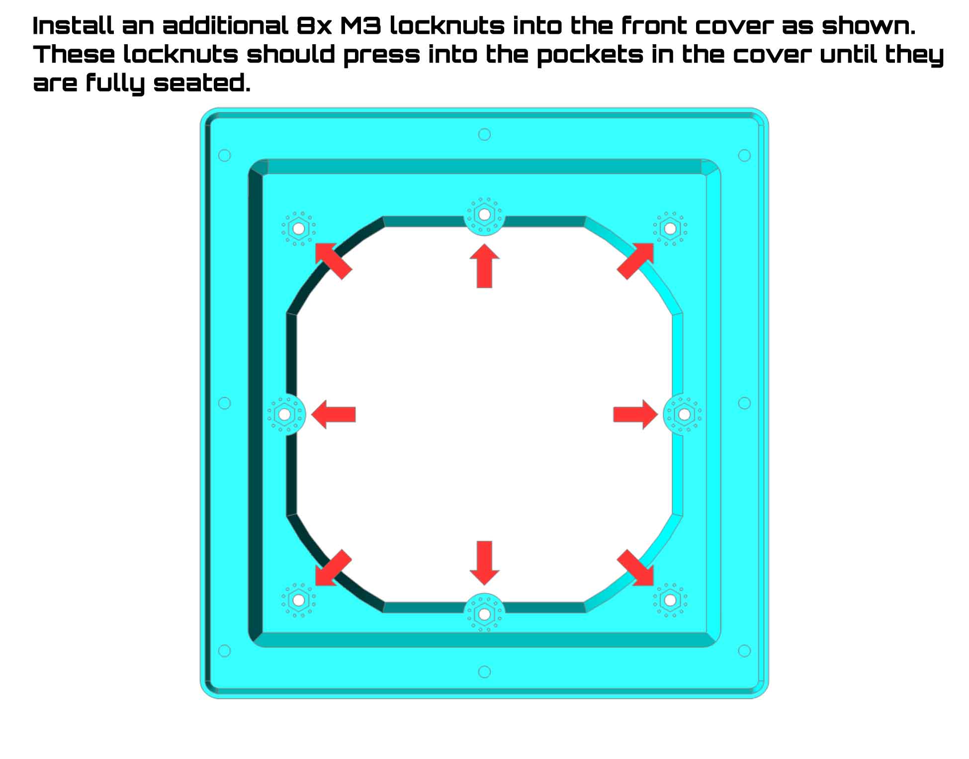
Step 5: Install the M3 locknuts into the front cover as shown. There will be a total of 16 locknuts installed in the cover when this step is completed. Note that some of the locknuts slide into slots on the inner edge of the front cover, and due to the print orientation, some of these go in at a 45° angle.
The “direction" of the M3 locknuts is important to observe. The locknuts need to be installed so the direction of the outermost set of 8 locknuts (center pic below) will be compatible with the screws used to secure the front cover to the "can” (see following step 7 if this is unclear). The direction of the inner set of 8 locknuts (right side pic below) will need to be compatible with the screws which secure the front cover plate insert (with the magnets) to the front cover (see step 6). Removing the locknuts from the pockets if they are installed backwards is going to be difficult, so be sure to understand the direction they need to be installed in, before seating them.
 |  |  |
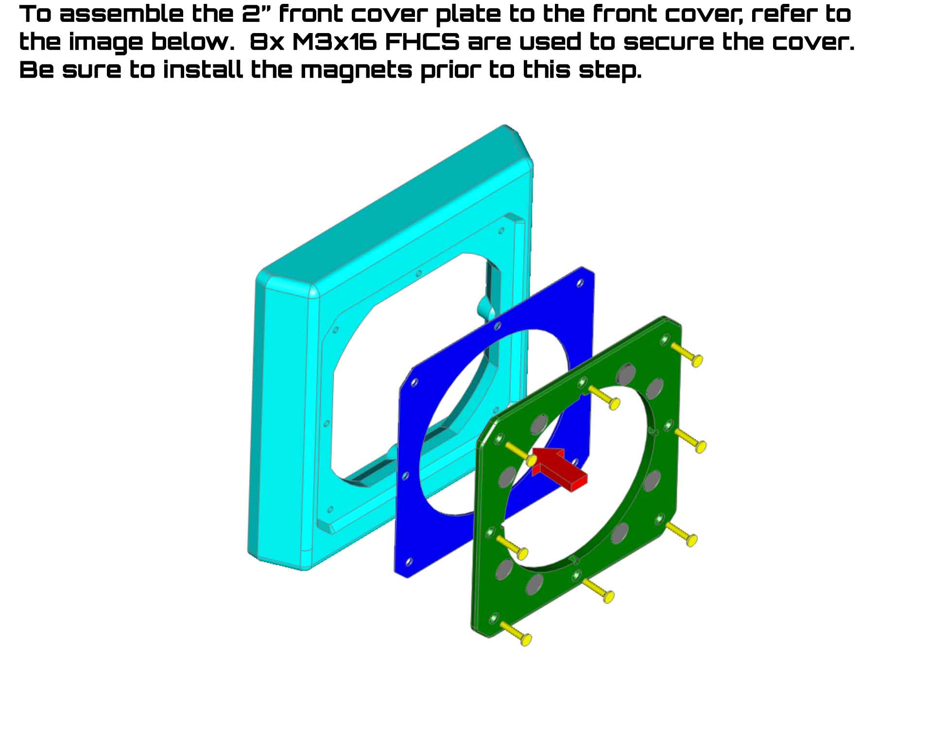
Step 6: You can install the front cover plate insert into the front cover using 8x M3x16 FHCS screws as shown. If using the optional TPU gasket version, the gasket will go between the insert and the front cover during this step.
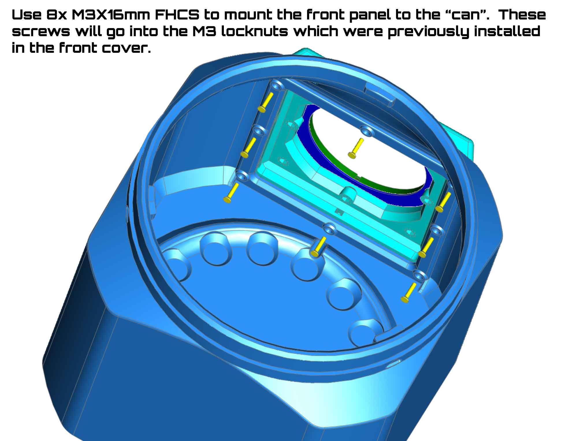
Step 7: Install the assembled front cover with the insert into the can using 8x M3x16 FHCS and 8x M3 locknuts as shown. If using the optional TPU gasket version of the front cover (not shown), the gasket will go between the front cover and the "can" during this step.
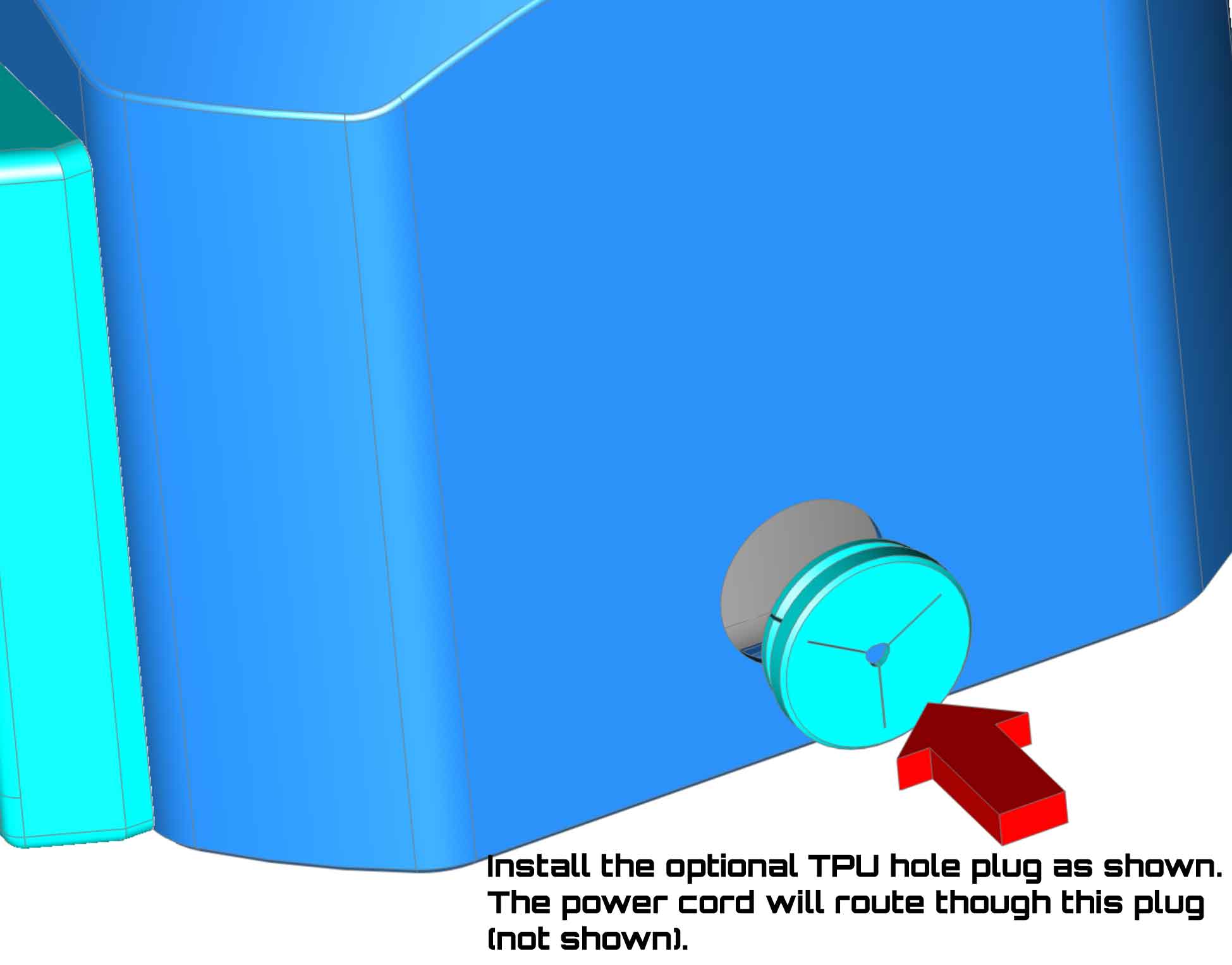
Step 8: Install the filter into "can" and run the power cord through the power cord hole. You can install the optional TPU plug cover for the power cord hole at this point. Check that the feet on the Core 200S filter are setting into the indents for them in the base of the "can". The filter should be stable and should not rock when placed in the "can" base.
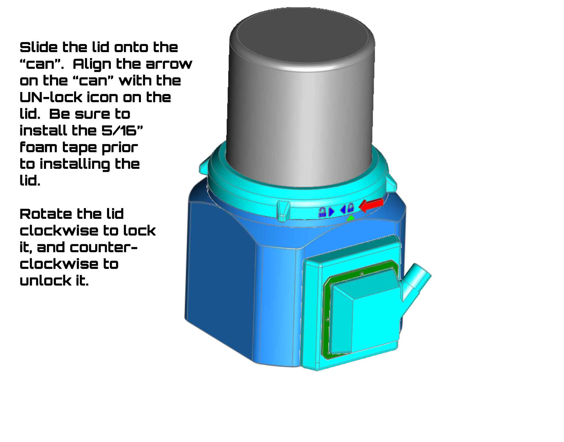
Step 9: Install the lid. The lid should slide over the top of the Core 200S, and then rotate counter-clockwise to lock with the "can" (you can follow the arrow icons on the lid to see the lock and unlock orientations).
Step 10: Install the remaining 8x 10x3 cylinder magnets into the 2" duct. Be sure that the poles are facing in the same direction and will attract to the magnets previously installed into the cover insert in step 4. These magnets will not be easily removed once installed, so be sure to get them oriented correctly. Use superglue to set them in position.
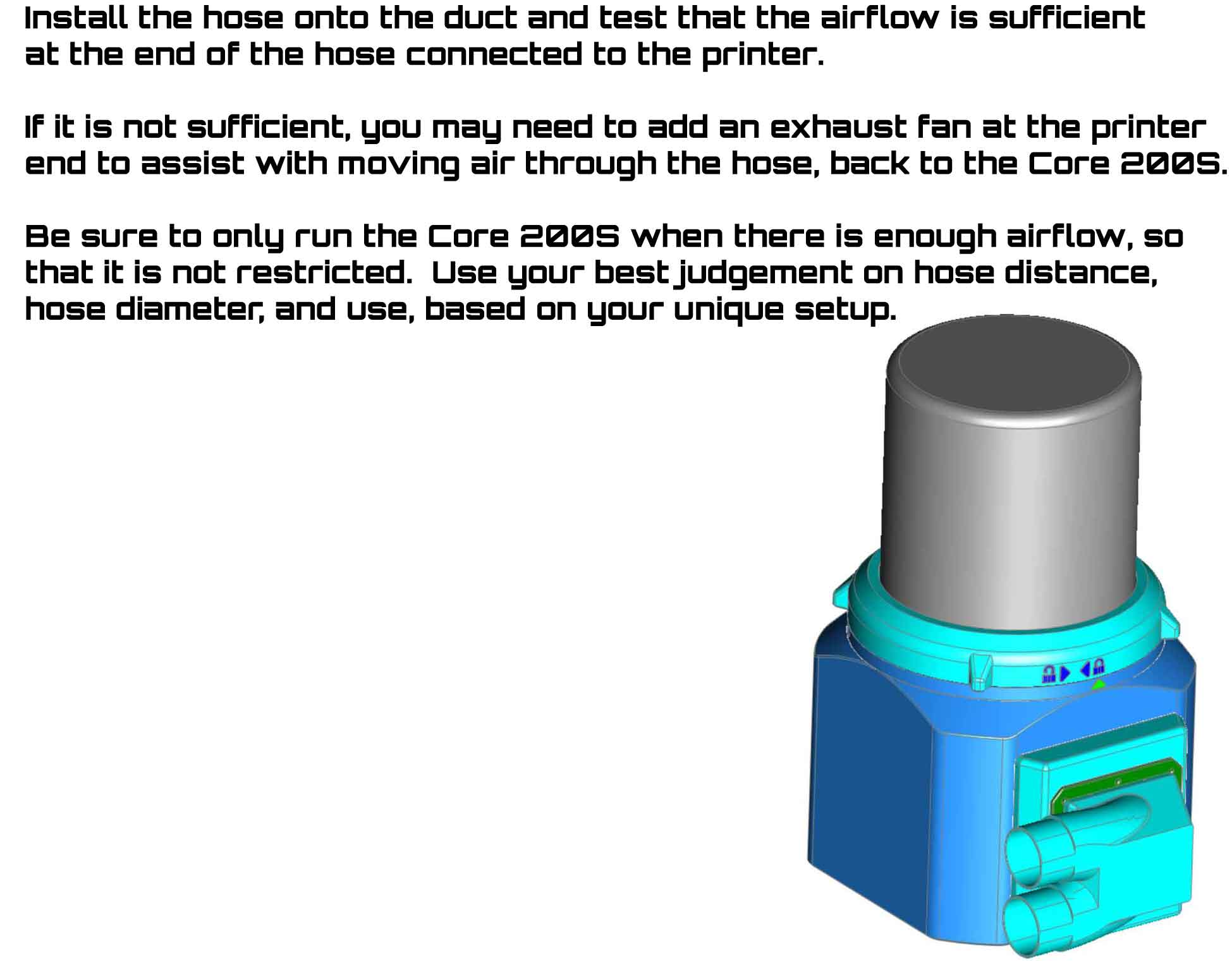
Step 11: Install the hose onto the duct and test that the airflow is sufficient at the end of the hose connected to the printer. If it is not sufficient, you may need to add an exhaust fan at the printer end to assist with moving air through the hose, back to the Levoit Core 200S. Be sure to only run the Levoit Core 200S when there is enough airflow, so that it is not restricted. If you have an H2C or other printer that has louvers to shut off the exhaust from the printer, be sure they are open when running the Core 200S, so there is no restriction on air flow. Use your best judgement on hose distance, hose diameter, and use of the filter, based on your unique setup. Monitor the system to make sure it is operating normally.
This is currently released under the CC BY-SA-NC license, so feel free to remix the ducts or other parts to suit your needs. I plan to cross post this to Printables soon. If you have a duct size you need, or want to remix a duct, let me know and I can post the STEP files required to help with that (it's a bit of work so I don't plan to do that unless it's necessary). Please note that commercial use is not permitted by the license.
One additional thought is that it may be possible to integrate a Levoit Core 200S (wireless version) with the printer using the HA-Bambulab integration for Home assistant. The wireless version of the Levoit filters appears to have an integration with Home Assistant (https://www.home-assistant.io/integrations/levoit/), but as I do not own one of these filters (and am very new to useing Home Assistant), I have no way to test it. If it's possible however, it would be a cool way to control the filter based on the printer's operational state. If anyone gets that working, please share about your experience with it in the comments.
Related Models:
These related models were also suggested and tested by MadMopar, and use the same duct design as this Levoit Core 200S filter. These models were used with his complete exhaust and filtering system, along with the Levoit Core 200S based filter here. They are currently posted only on Printable. If you decide to try out the untested 2.5" ducts, please post a comment with your thoughts.
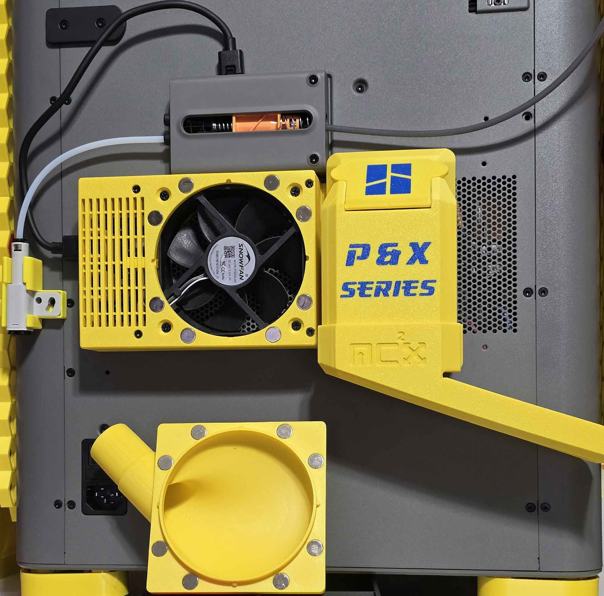
Low Profile P2S Chamber Exhaust Fan Kit ver1.0
Note that the “poop chute” shown in the images below is a remix of Mc2.project3D's “Inspectable Waste Chute – Series P / X / H2”.
| 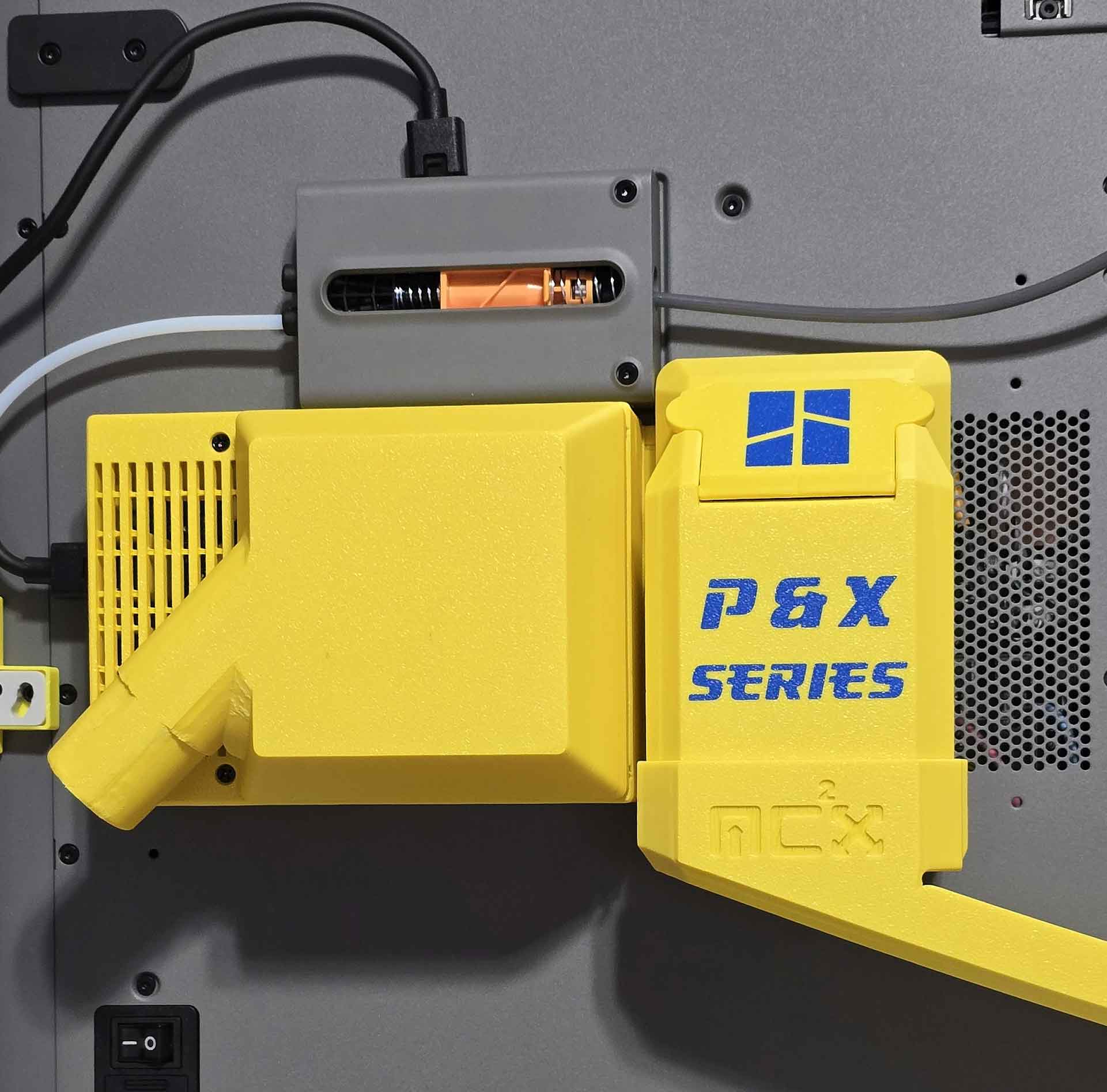 |
Bambu P1S 2" and 2.5" Magnetic Duct Adapters
This is an adapter to mount a duct to the exhaust on a P1S printer. It uses the same magnetic duct design as the Core 200S filter and the above P2S low profile exhaust.
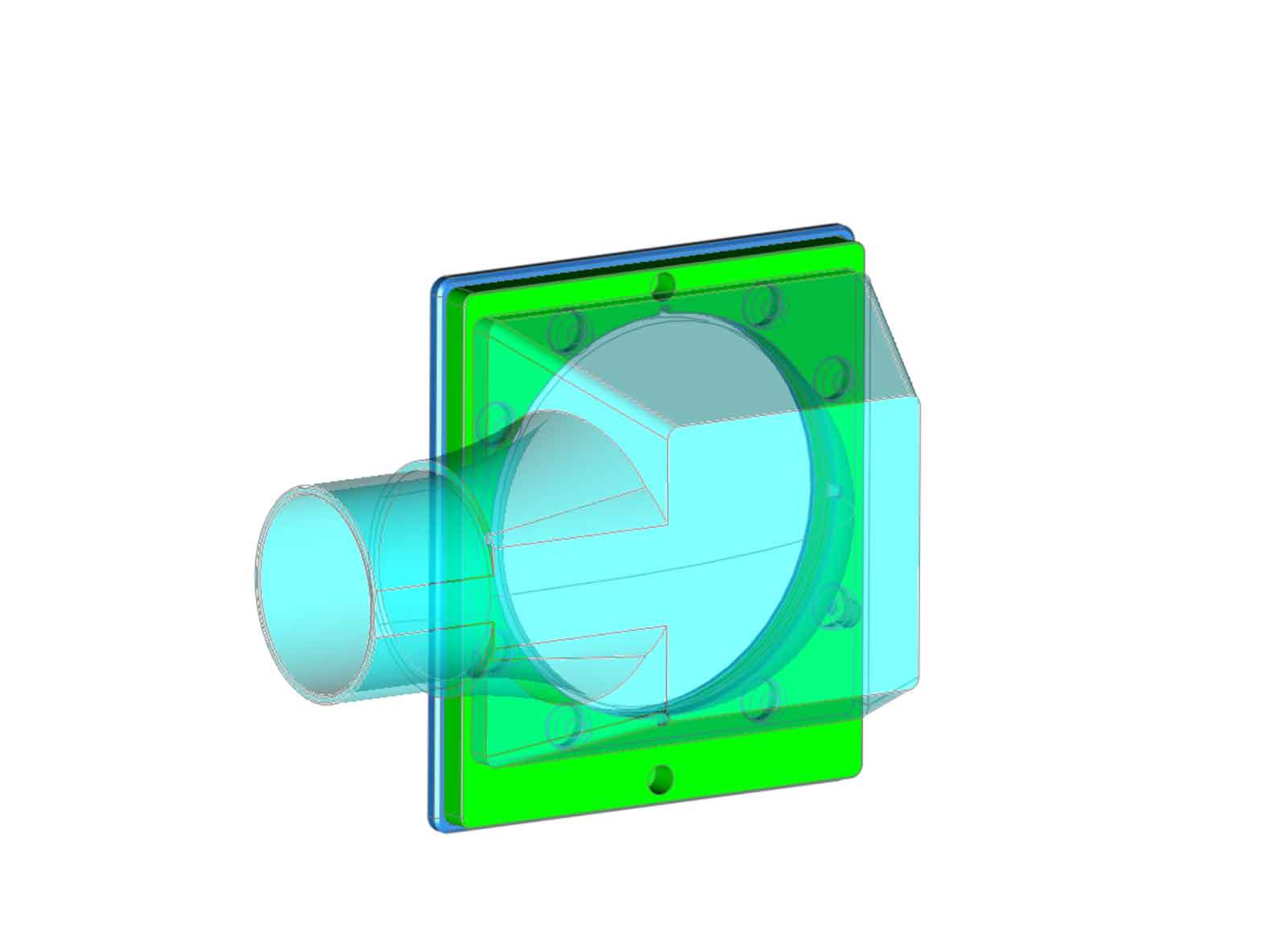
2.5" Ducts for Bambu P2S and P1 Exhaust (untested)
These 2.5" ducts are designed to work with this Core 200S filter as well as the P1 and P2 exhaust parts shown above. They have not been tested and are only available on Printables at this time. If you use these, please post a comment with your thoughts on the ducts.
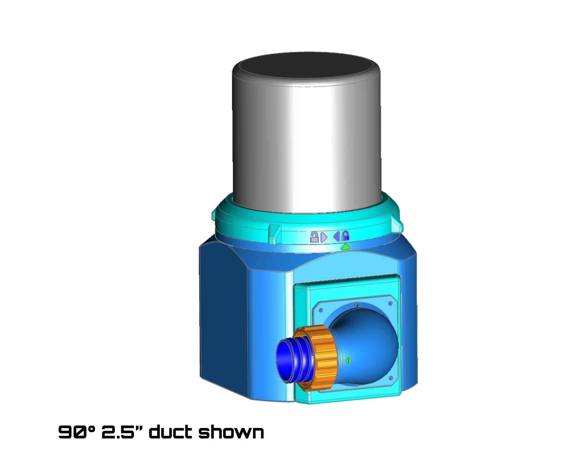 | 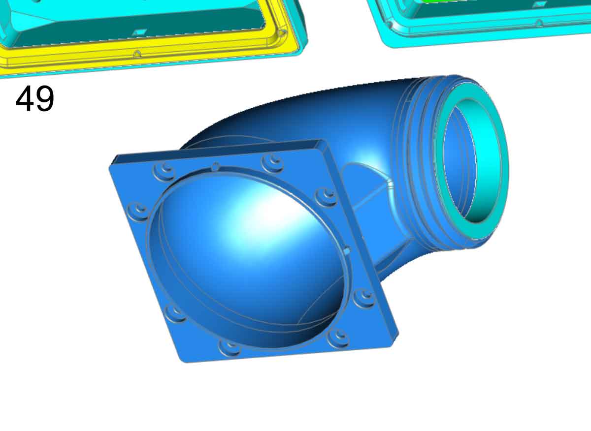 |
If you find these models useful, please post a like or a comment with some pics of your prints.
You can find the other things I'm working on at my blog here. You can also follow me here on MakerWorld, to see what new stuff I post. If you would like to support my work, you can Buy Me A Coffee using this link:
[https://www.buymeacoffee.com/mystoopidstuff](https://www.buymeacoffee.com/mystoopidstuff)
Thanks for looking!
Changelog:
6/11/2026: Uploaded design.
6/16/2026: Posted the design on MakerWorld
Levoit Core 200S 3D printer Filter Adapter

Publicado em 12 de jun de 2026
Gostou deste modelo? Crie uma conta grátis para salvar seus favoritos e voltar a eles depois.
Criar conta