Você está no 3DFinder
Buscamos em Thingiverse, MakerWorld e Printables ao mesmo tempo para te dar o melhor de cada uma.
Descrição
Ok, so I just wanted to try and make a 3D printable DIY sequential shifter that met a few criteria:
1 - Simple / easy to assemble.
2 - Wanted the throw (lever pull travel distance) to be more than the others I have 3d printed.
3 - Have a nice amount of force required (resistance) to pull the lever.
I looked at many real-life sequential shifter videos and looked up specs. Seems depending on brand and setup travel could be from 3 to 6 inches and force required from 3 to 10 lbs of force.
There are 3 lever lengths to accommodate rig setup and shifting feel.
The length of the lever will determine the travel and force.
These are rough measurements (not exact).
Long lever - 3.25 lbs, 3 inches of travel
Mid lever - 5 lbs, 2.5 inches of travel
Short lever - 7 lbs, 2 inches of travel
In purchased parts its roughly $28 in parts and you will have some parts, screws and nuts left over to maybe make another or for other projects.
Can be cheaper if you already have some of the items or find cheaper sellers.
Print Parameters:
Tested with 4 walls 10% gyroid infill and it all holds up well. You can add walls if you shift like the hulk.
The tracks are set to 8 walls, I suggest printing the tracks with PTEG as PLA can warp over time.
The carriages are set to 8 walls, also printed in PTEG for durability.
All other parts are printed PLA plus and set to 4 walls, 10% Gyroid infill.
The levers have two cylinder modifiers to add extra walls to the spring guide shafts for structural strength so don't delete them.
The bearing spacers are set to 100% infill.
BOM (purchased parts)
1 - 6700zz bearings - Quantity needed = 4
2 - 1.0mm x 15mm x 10mm (wire diameter x length x spring diameter) springs - Quantity needed = 4
3 - M4 X 40MM DOWEL PINS (guide rods) - Quantity needed = 4
4 - M10 nuts - Quantity needed = 2
5 - Plunger ball spring retainer 12mm x 16mm - Quantity needed = 2 - AliExpress
6 - Zero delay arcade controller or Arduino or whatever you want to use. The arcade controller is the simplest and you can use the other button inputs to ae a button box (that's what I did). And you can wire it up to your Fanatec CSL dd wheelbase (look at the comments for a pin diagram).
7 - Micro switches - Quantity needed = 2
8 - M4 x 45mm screws - Quantity needed = 9
9 - M4 Nuts = Quantity needed = 9
10 - M4 x 20mm conical screws - Quantity needed = 2
and miscellaneous wires, plugs zip ties etc... depending on how you decide to implement it.
Component Assemblies
Bearing Carriage assembly
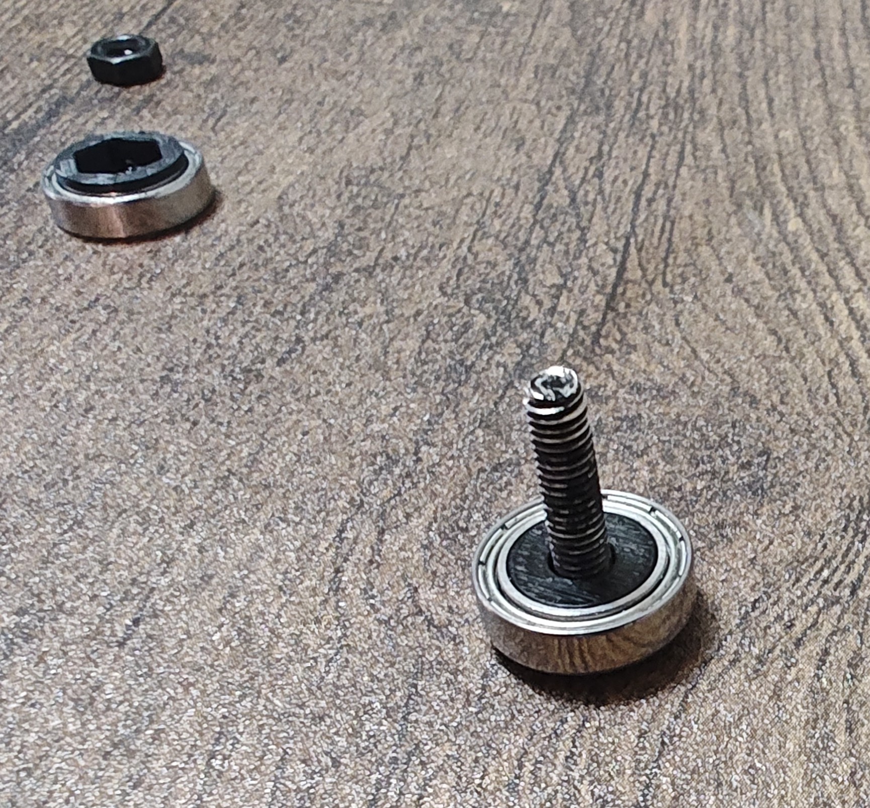
1 - Insert the M4 x 20mm Conical screw in the printed conical bearing spacer.
2 - Then place the bearing on the same screw.
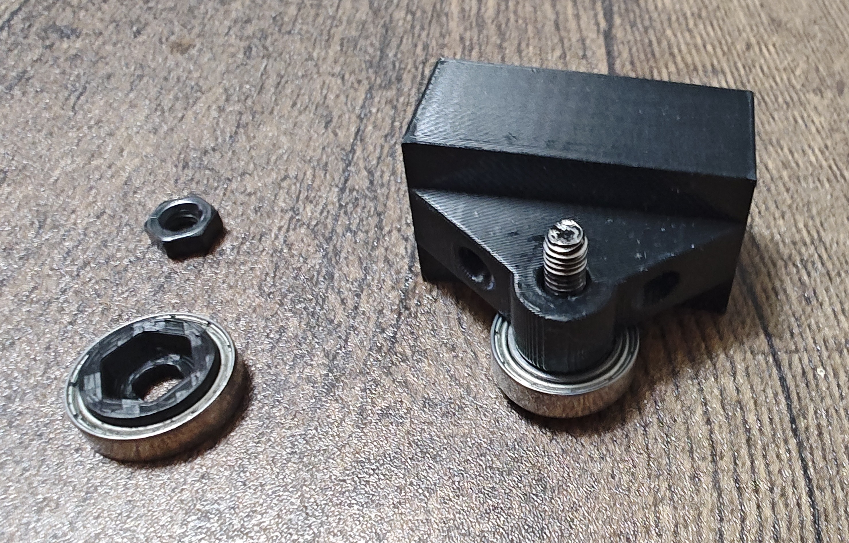
3 - Insert the screw + bearing + spacer through the carriage screw hole.
4 - On the other side place the nut bearing spacer + bearing + M4 nut.
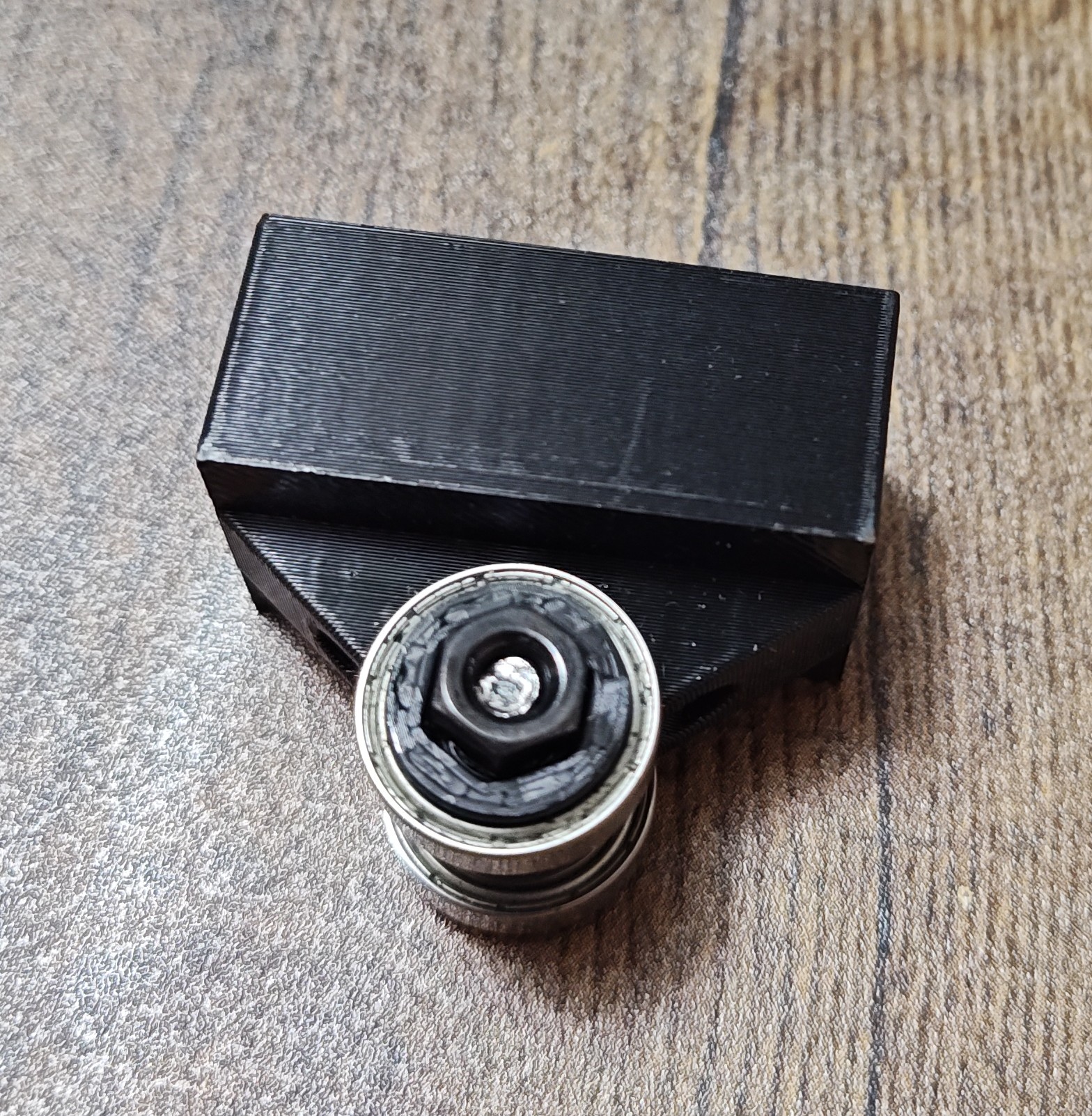
5 - Tighten (you can use a dot of locktite).
6 - Repeat all for the second carriage
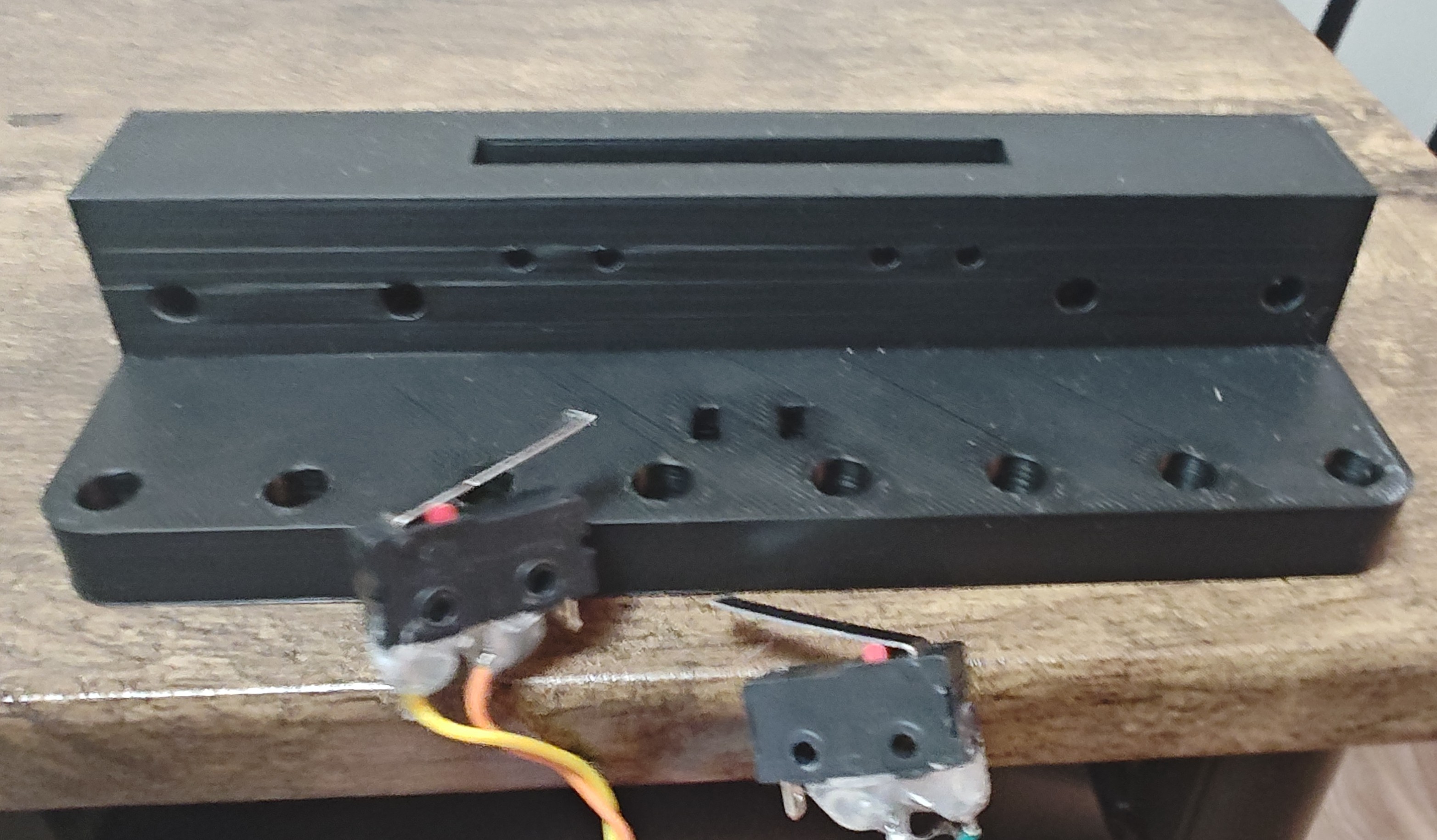
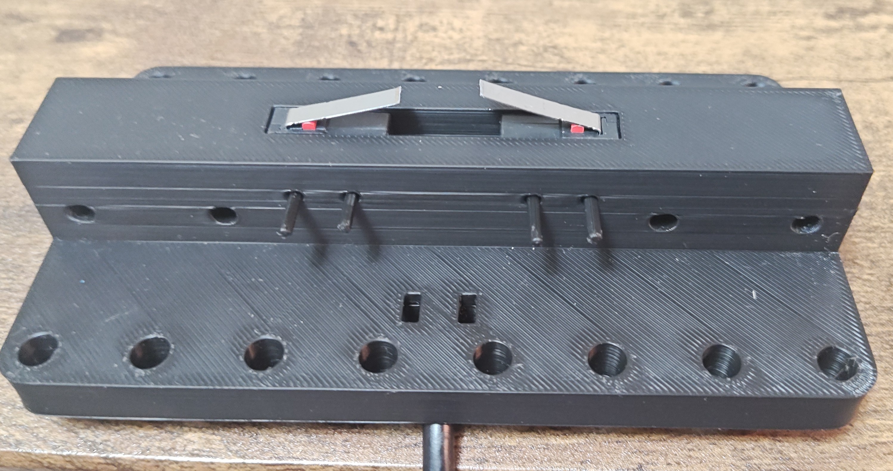
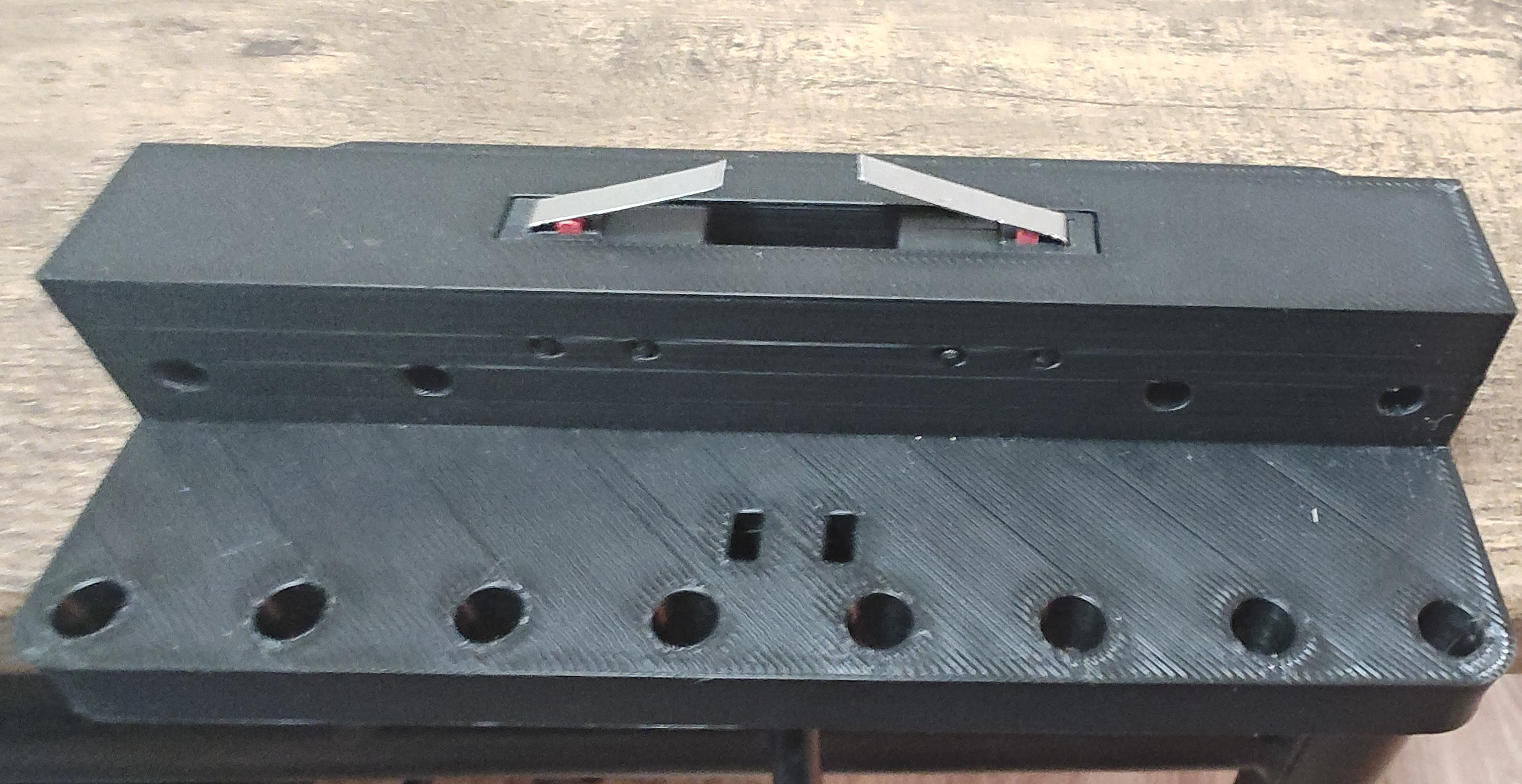
Switch assembly
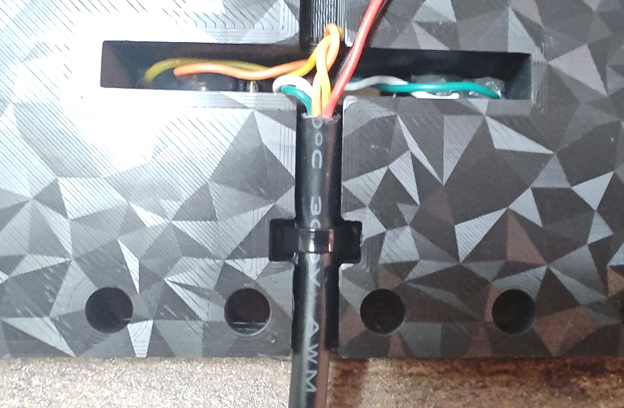
1 - Attach/solder the wires to each switch (the two pins closest to the red button). I put hot glue to help secure the wires and trimmed the glue with wire cutters.
2 - Place the switches in the switch housing from the bottom up with the levers pointing towards the center.
3 - Insert the 4 printed retaining pins to hold the switches in place.
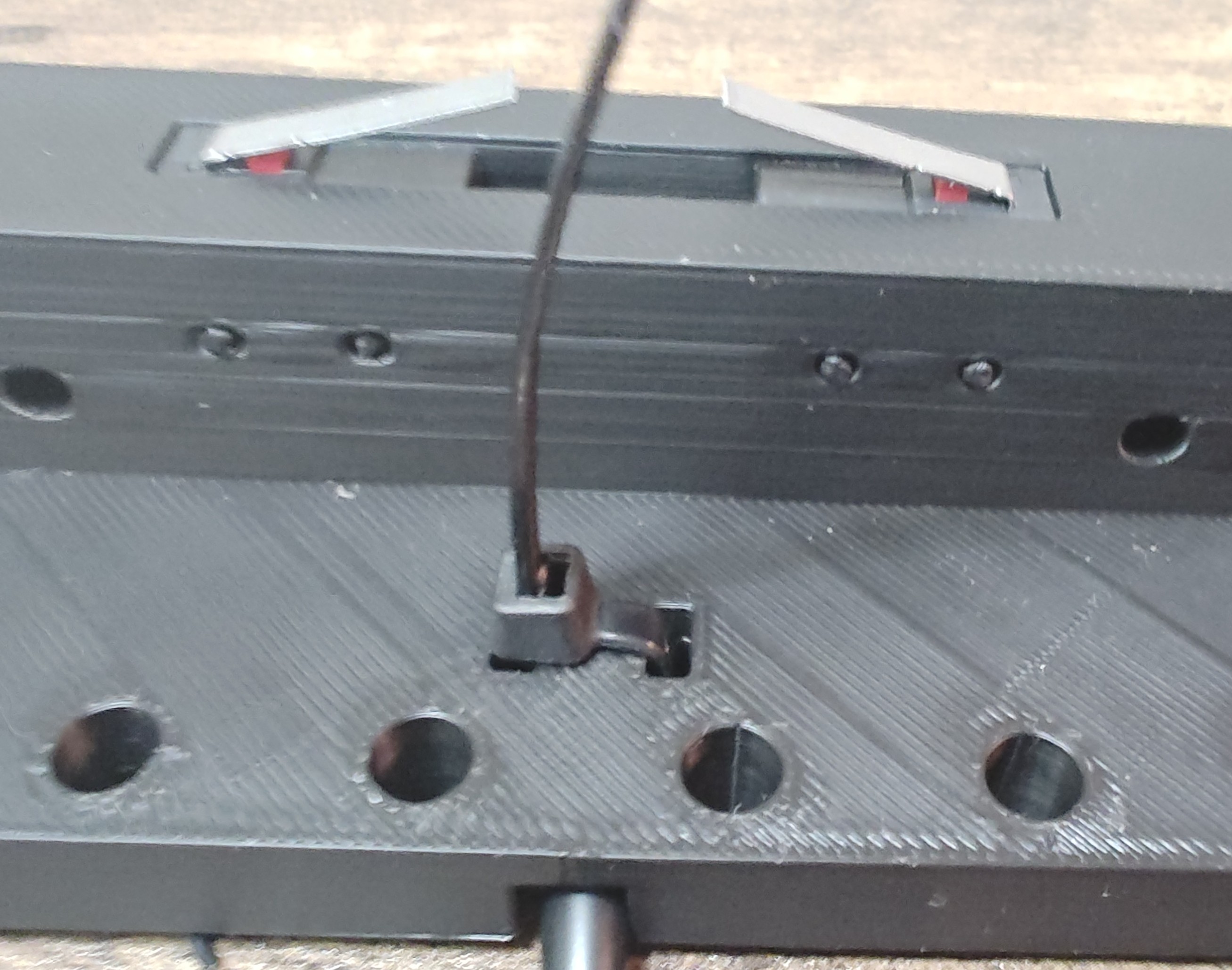
4 - Place a ziptie from the top down and loop it back upwards to secure the cable tightly in place.
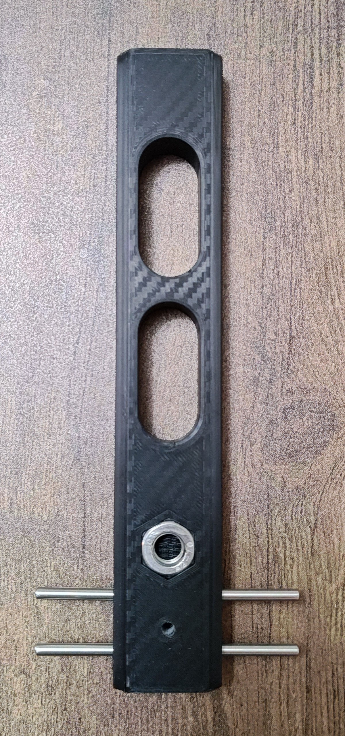
Lever Assembly
1- Insert the M4x40mm dowel pins into the 4 holes on the lever. It is a tight fit on purpose. You can tap them in lightly with a hammer or push down on the lever with the guide rods facing down on the floor like I did.
2- Place the M10 nut on each side of the lever.
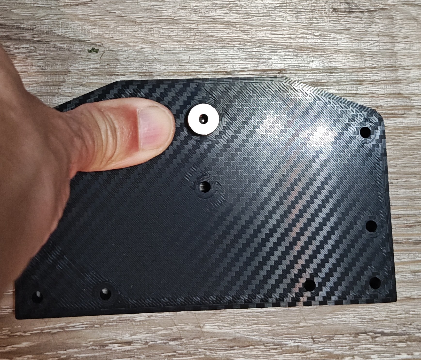
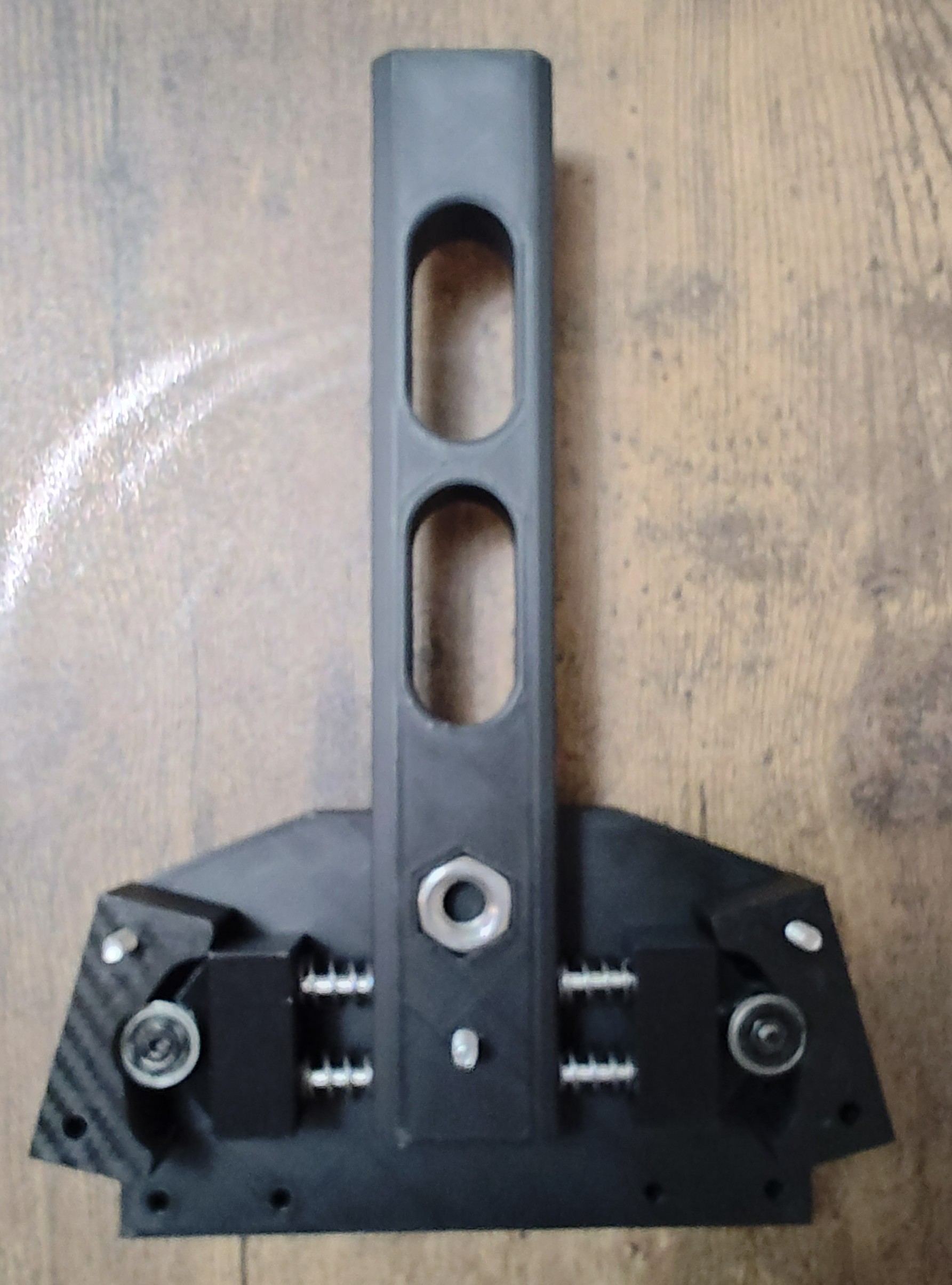
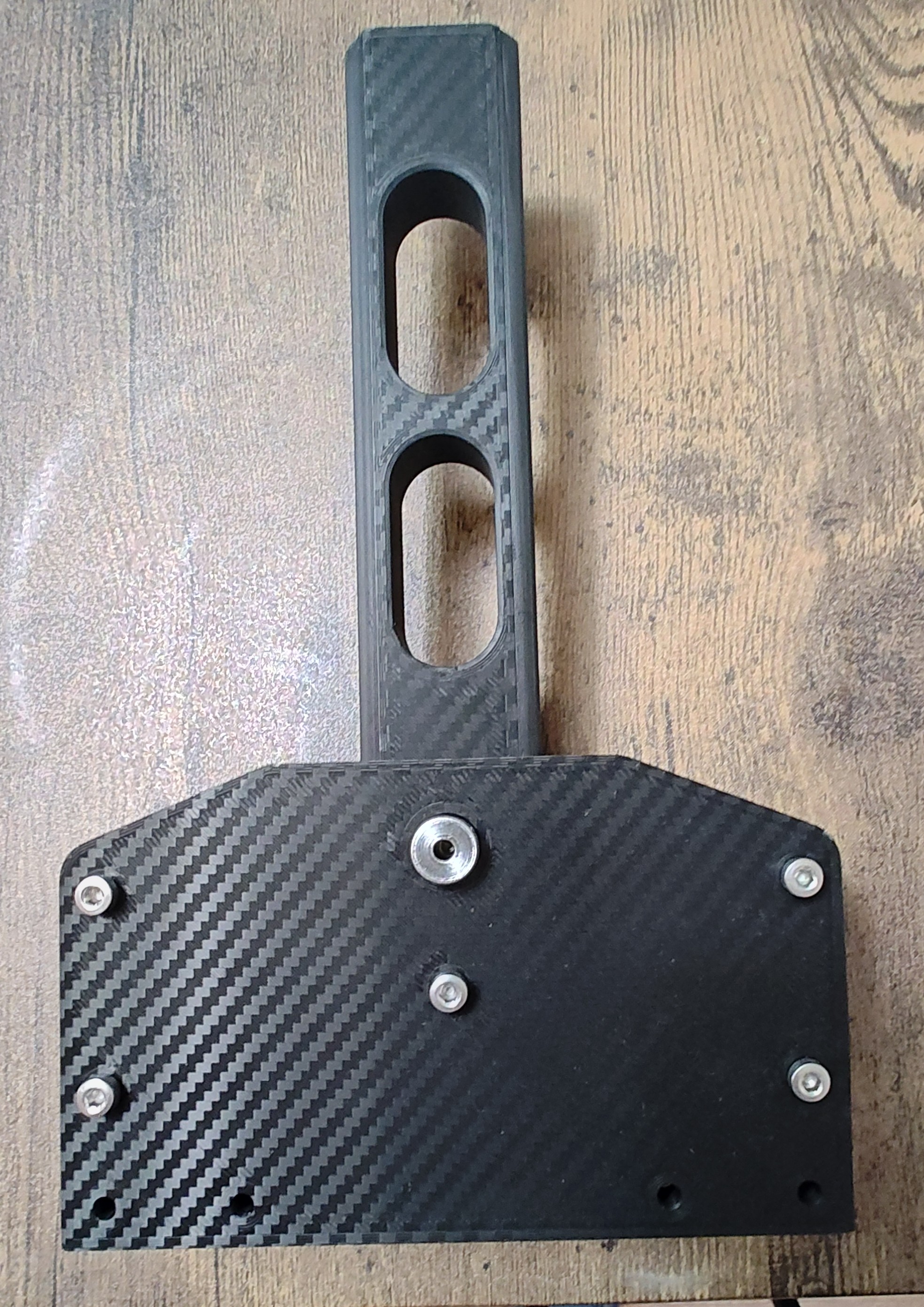
Face/side plate Assembly:
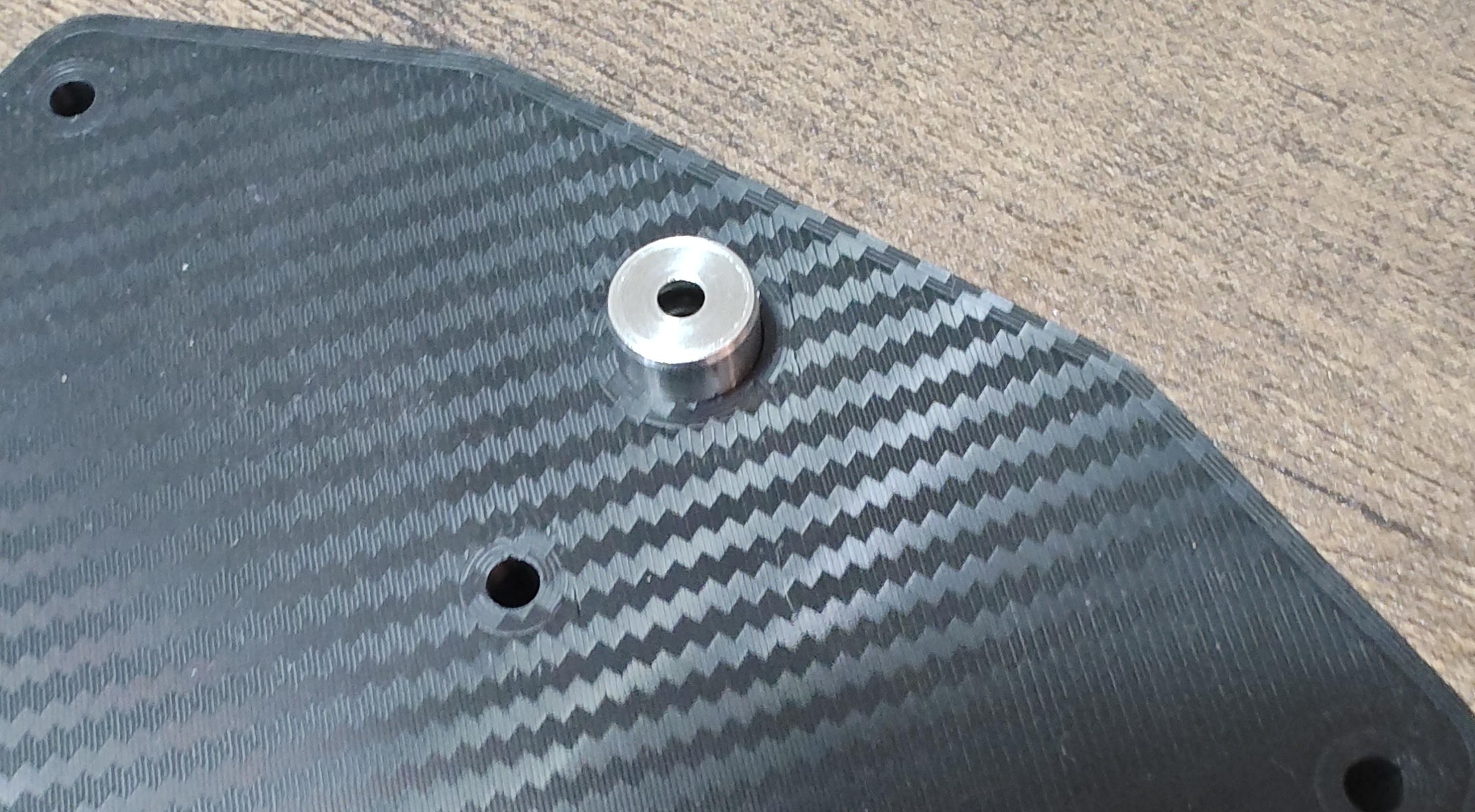
1 - Insert a plunge retainer on each face/side plate. There is a recess for the lip of the plunge retainer to sit flush. This side of the plate goes facing inward.
I placed it on the hard floor and pressed down on each side of the plunge retainer until it was completely seated in the recess.
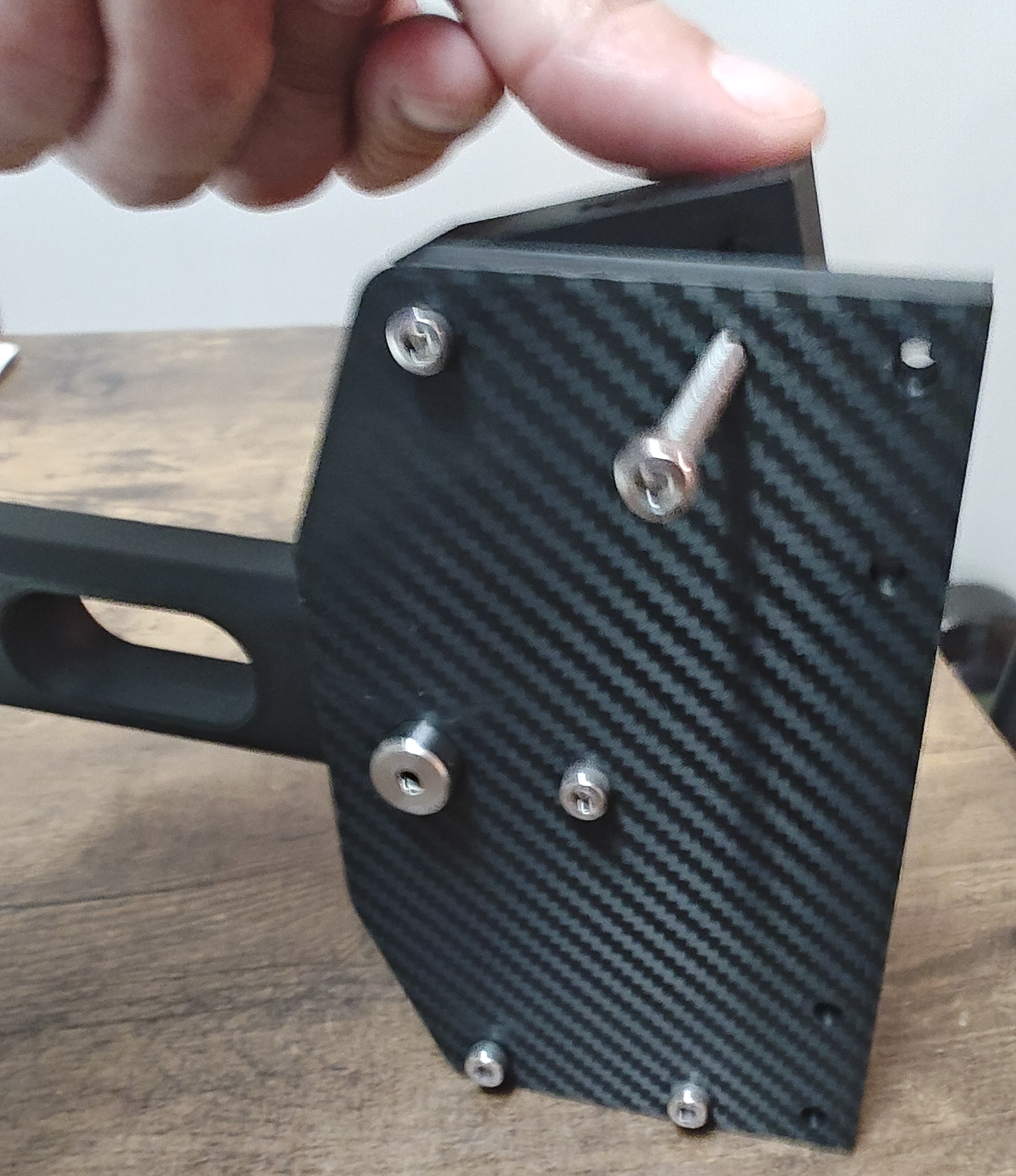
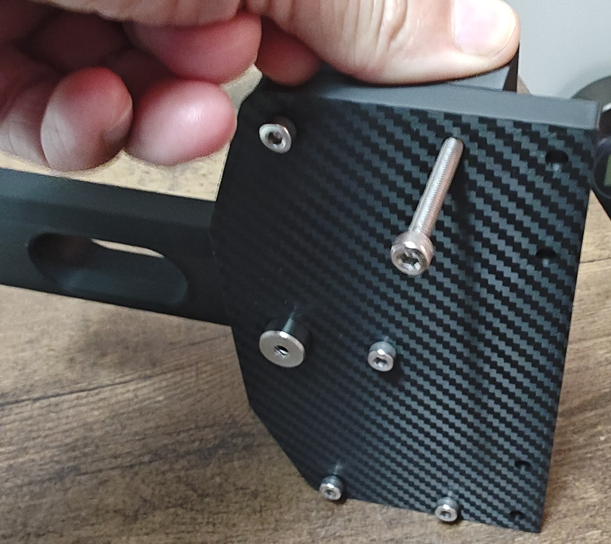
(I printed mine on a carbon fiber pattern pei plate to give it a carbon fiber look).

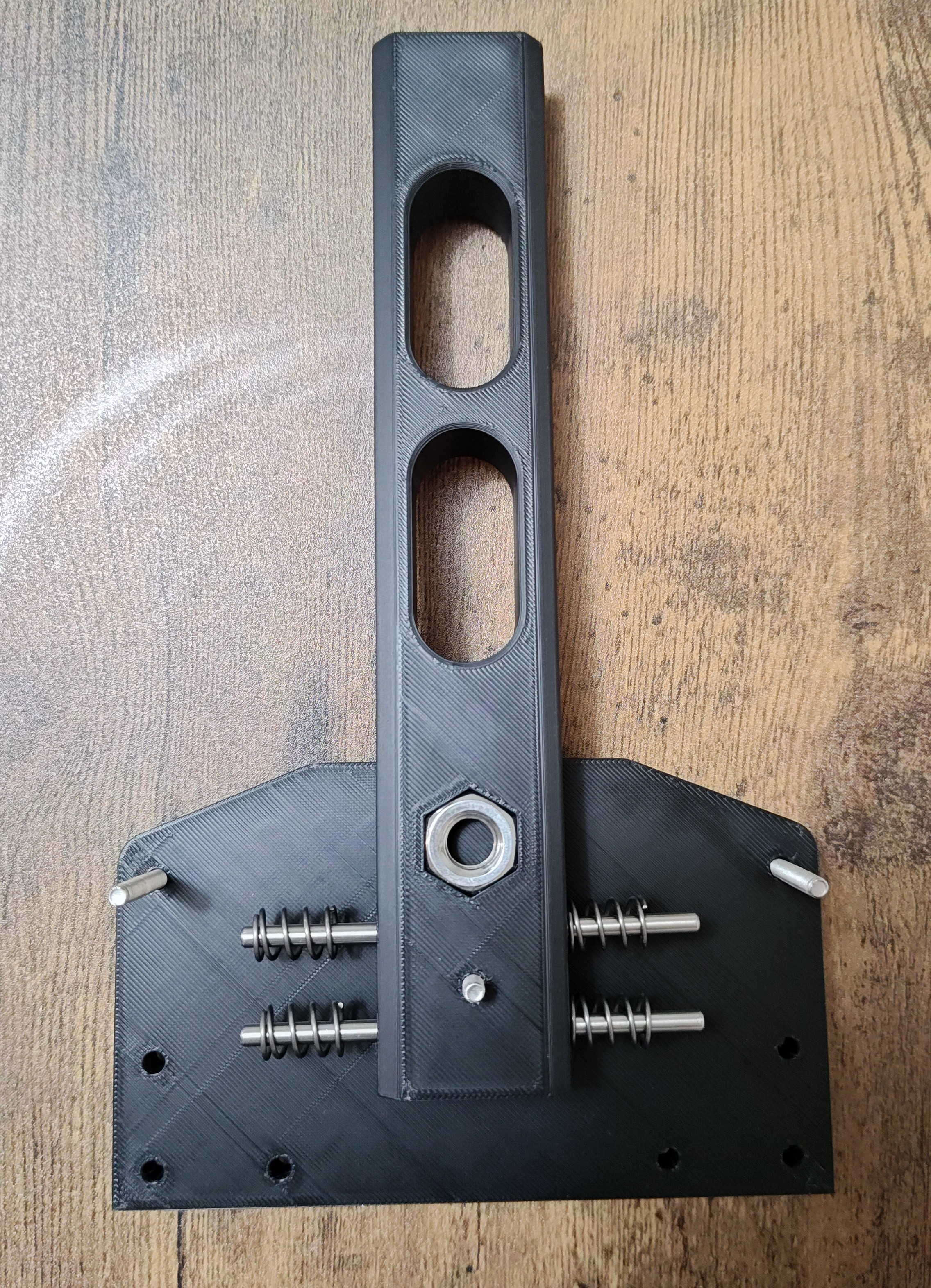
Complete Assembly
1 - Insert a M4 x 45mm screw in the center hole of the side plate (for the lever) and one M4 x45mm screw at the top corner on the left and right side.
2 - Slide the lever on the center screw
3 - Place a spring on each guide rod
4 - Slide the bearing carriage on to the dowel pins each side of the lever
5 - Place the tracks on the one top screw on each side. The bearing carriage will push them outward
6 - Place the assembly on its side and push the track down to align the bottom track hole, hold it in place and insert the other screw for the bottom of the track. Repeat for the other side.
7 - Place the other side plate on top and tighten the screws/nuts. You may need to push the tracks inward a little to align the screws with the side plate holes. The springs tend to push the tracks outward tilting the screws.
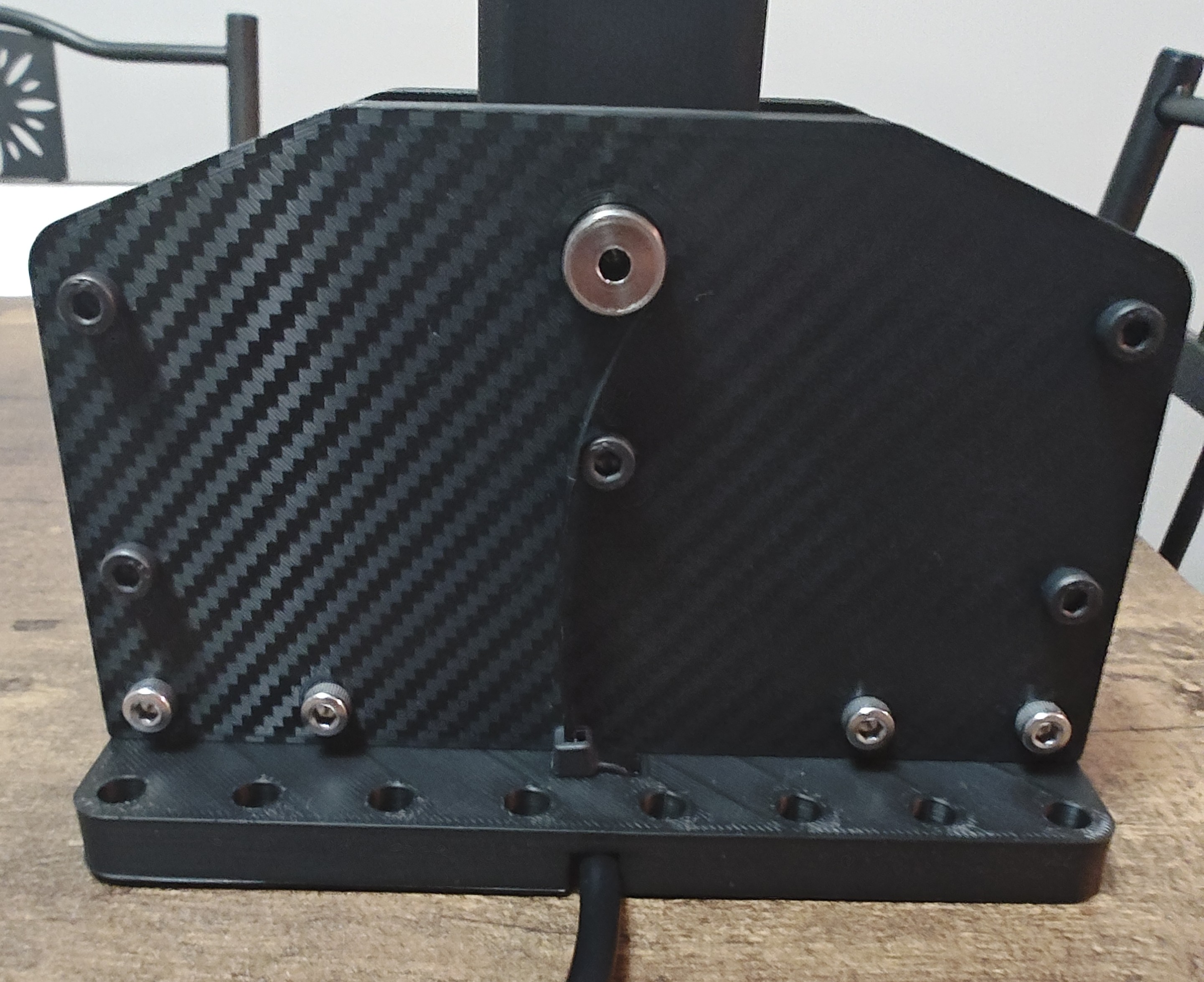
8 - Insert the switch assembly at the bottom of the sequential housing and secure it with either 2 or 4 M4 x 45mm screws/nuts
9 - Insert knob/lever connector into the lever and knob of your choice (you can check my other posts for other knobs).
10 - Bolt the base with M6, M5 etc… screws to your shifter mount.
11 - Connect the wire to your controller of choice and to your computer
Start shifting and drifting.
Later I will be posting the levers with added micro switch to use as return to neutral or whatever you want.
And I will be adding an old school style bent shift lever for it.
Stay Sidewayz...
DIY 3D printed SIM Racing Sequential Shifter

Publicado em 19 de mai de 2026