Você está no 3DFinder
Buscamos em Thingiverse, MakerWorld e Printables ao mesmo tempo para te dar o melhor de cada uma.
Descrição
My Educational Mechanical Examples Series
This model is one of my educational mechanical mechanism examples on 80mm x 80mm base plates.
You can find all models of the series in this collection => [Mechanical Mechanism Examples]
The present model
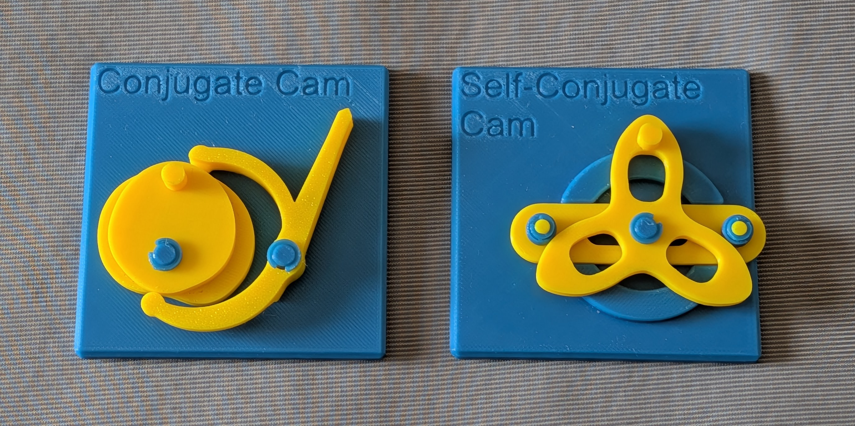
These are educational models of conjugate cams. One is a normal conjugate cam, the other is a self-conjugate cam.
Brief Description
In a typical cam mechanism, the follower is restrained by the cam only from one side. So, preload supplied by gravity or by a spring acting from the opposite side is required to keep the follower in constant contact with the cam; without it, the follower separates from the cam profile and the intended motion breaks down. Even with preload, at sufficiently high speed the follower can still lose contact with the cam profile. To extend this one-way constraint into a two-way constraint, a second cam can be added that restrains the follower from the opposite side. The two cams are designed in concert so that they impose the same motion law on a pair of followers rigidly connected to each other from both directions, fully constraining the motion of two followers whose relative position is fixed, without relying on springs or gravity. The added cam is conjugate to the original cam, and the overall arrangement is known as a conjugate cam mechanism or, emphasizing the positive drive, a desmodromic cam mechanism. The word desmodromic derives from the Greek δεσμός (desmós, constraint) and δρόμος (drómos, course). This terminology is most commonly encountered in the context of four-stroke engine valve actuation, where conjugate cams open and close the intake and exhaust valves without valve springs — an arrangement known as desmodromic valve actuation.
A groove cam (also called a face cam with a slot) also constrains the follower in both directions without preload. However, a conjugate cam mechanism, with its open contact surfaces, allows easier lubrication and debris clearance, which can be advantageous in high-speed applications.
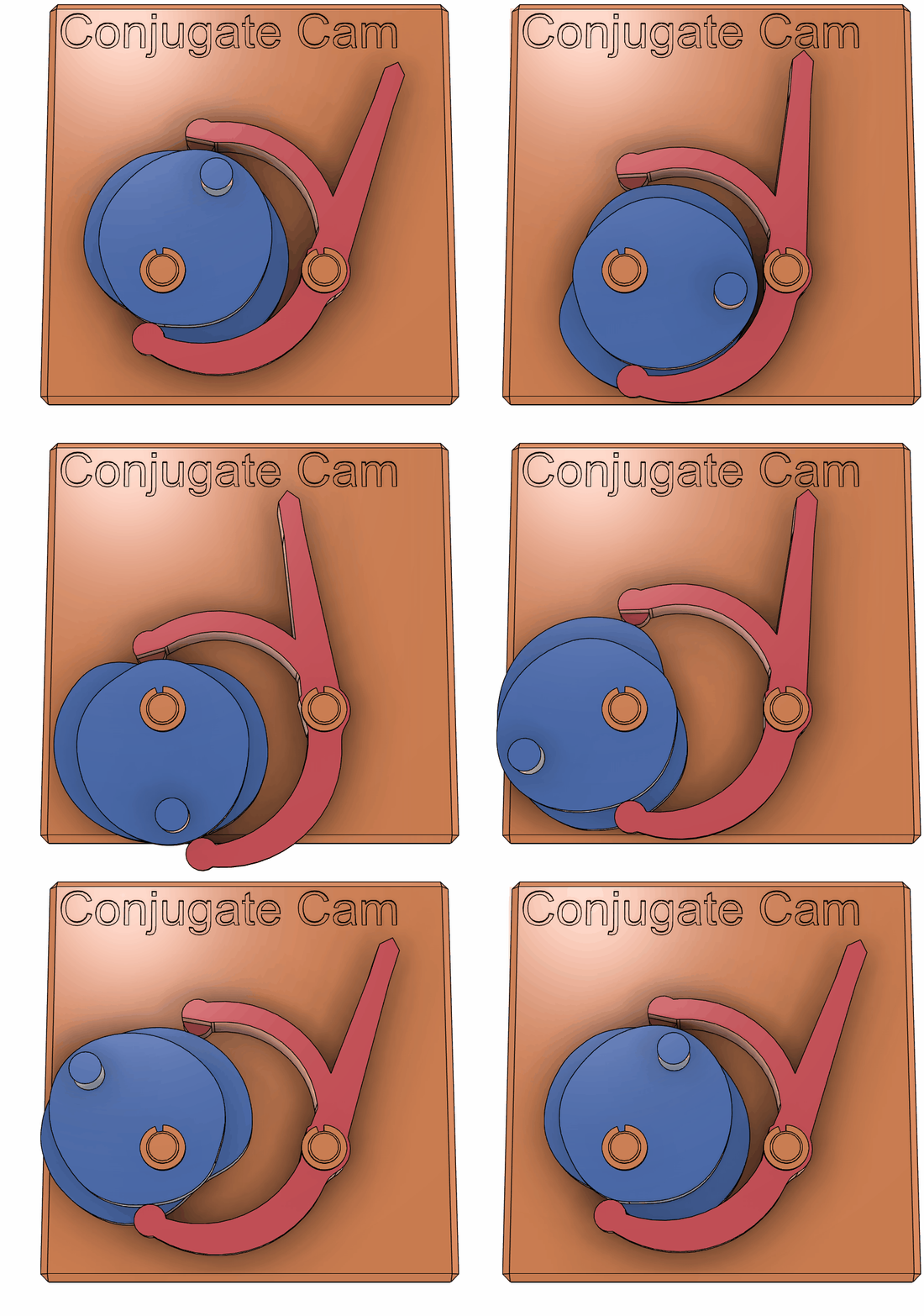
In the first mechanism shown here, the top cam was first designed to be mirror symmetric and the bottom cam was designed to be conjugate of the top cam. Note the bottom cam is not mirror symmetric because of the asymmetry of the follower motion against the mirror.
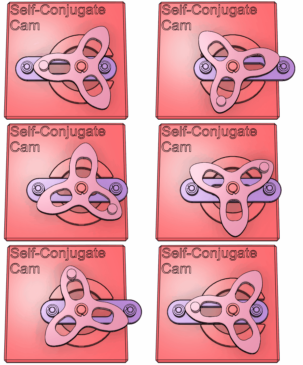
In the second mechanism shown here, the pitch curve has constant width as measured along any line passing through the cam pivot, which allows a single cam to serve simultaneously as its own conjugate. That is, one cam alone constrains two opposing followers at the same time, eliminating the need for a separate conjugate cam. In this sense, we refer to this cam mechanism as a self-conjugate cam, though this word is not common. Because only one cam is needed, the part count and assembly tolerance requirements are reduced; on the other hand, an inevitable trade-off is that the cam profile has less design freedom than in a conventional conjugate cam arrangement. For example, this model has three-fold rotational symmetry and mirror symmetry, which together reduce the independent portion of the profile to 1/6 of the full rotation. The constant-width constraint required for self-conjugation halves this further as it determines one side of the pitch curve from the other. As a result, only 1/12 of the full profile remains freely choosable to define the entire cam shape.
Reference
Related Models
Case
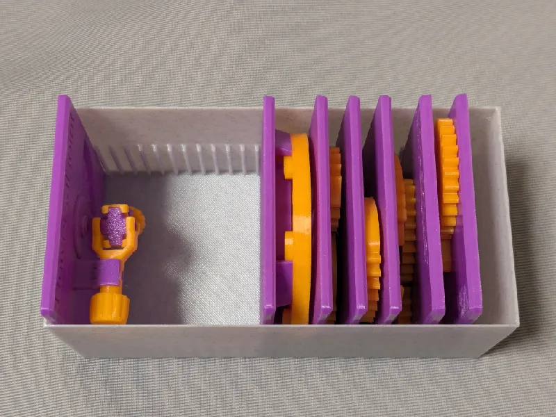
This model is compatible with the case included in my first set.
Printing
- Use the models named ???-printable.stl for printing.
The models named ???-assembled.stl are provided just to show how they should be assembled.
- Use well-dried PETG to have better dimensional accuracy.
- Use 0.1 mm or 0.08 mm layer height to have smoother surfaces.
- Use slow printing speed for overhangs.
- Select “Random” seam position to have smoother rotation.
Randomly distributed seam should be easily worn out after some wearing.Printing
Sanding and Filing
Note that, in this model, the rotation of the bases for bearings is intentionally made not too smooth.
Sometimes, the gears suffer from the stringing effect and/or elephant foot effect, resulting in a too tight fit to the shafts (they are designed with a 0.15 mm radial clearance).
If you see rough surface on the shafts due to stringing, sand off the roughness with a small piece of sand paper.
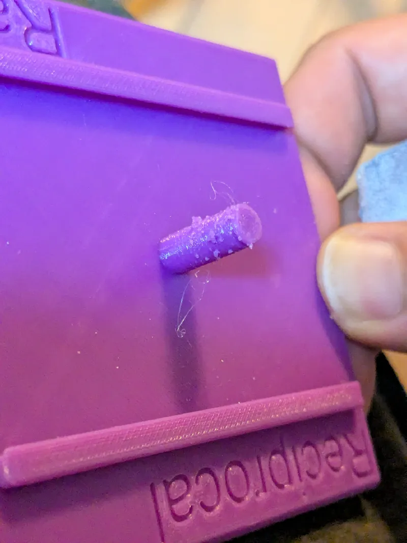
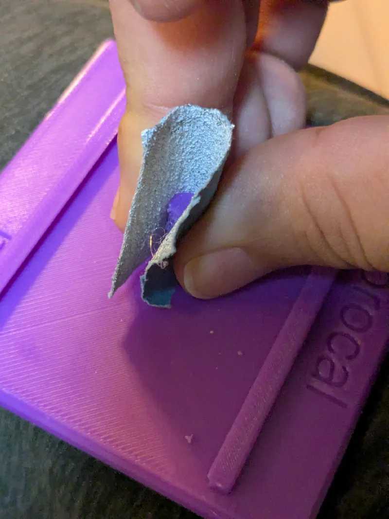
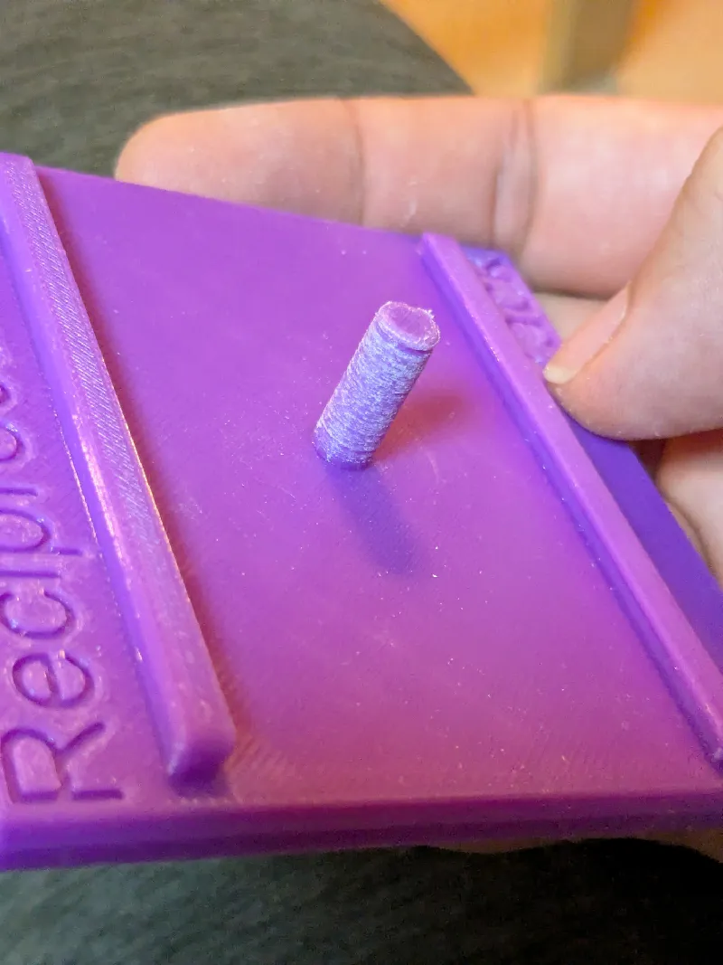
If you feel the gears do not rotate smoothly due to an elephant effect, widen the hole slightly by using a thin round bar file.
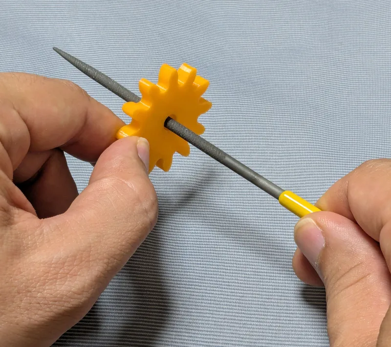
Without those issues, the parts should rotate very smoothly with minimal friction.
Assembly
Secure the parts with the retaining rings.
Other examples
You may also be interested in the models in my educational mechanical mechanism examples.
Find them in this collection:
[https://makerworld.com/collections/15048577-my-educational-mechanism-models](https://makerworld.com/collections/15048577-my-educational-mechanism-models)
Happy printing!
Acknowledgement
I got into gears thanks to K.$uzuki's amazing articles and YouTube videos. Many of the mechanisms shown in this series came from the introductions on his website. He also makes excellent gear models himself. This series wouldn’t have existed without his inspiration.
I learned a lot about technical detail of designing gear tooth profiles from Haguruma-No-Hanashi website. I’m truly grateful for that.
License
- The 3D model(s) are licensed under Creative Commons Attribution 4.0 International.
- However, the text and images on this page are copyright reserved.
Conjugate Cam - Educational Model

Publicado em 4 de mai de 2026
Gostou deste modelo? Crie uma conta grátis para salvar seus favoritos e voltar a eles depois.
Criar conta