Você está no 3DFinder
Buscamos em Thingiverse, MakerWorld e Printables ao mesmo tempo para te dar o melhor de cada uma.
Descrição
My Educational Mechanical Examples Series
This model is one of my educational mechanical mechanism examples on 80mm x 80mm base plates.
You can find all models of the series in this collection => [Mechanical Mechanism Examples]
The present model
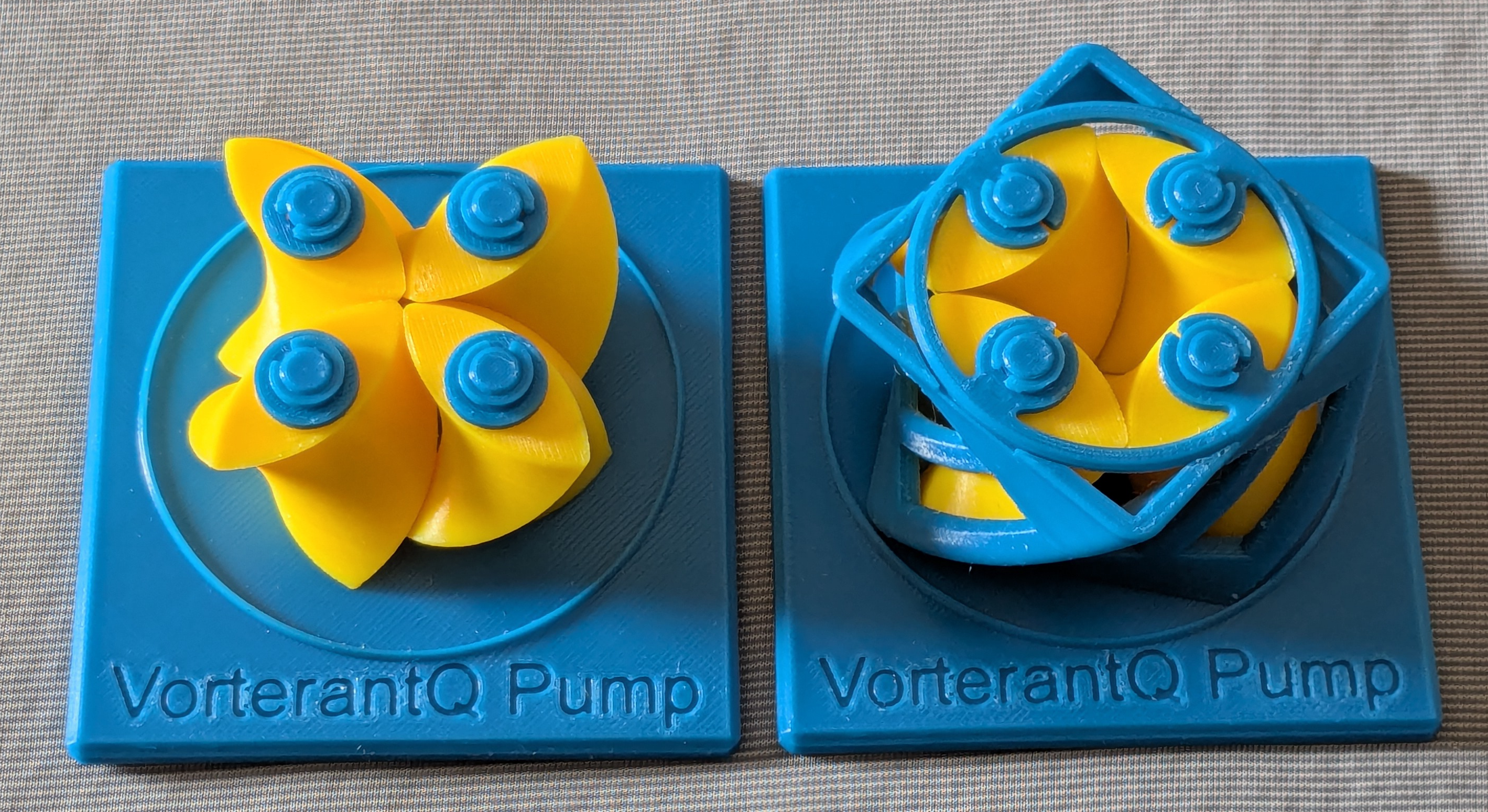
This model shows an educational model of a VorterantQ pump.
Brief Description
The VorterantQ Pump is a positive displacement pump in which four rotors spin in the same direction at the same speed. The sealed cavities trapped between the rotors travel along the rotational axes, transporting fluid. In this model, the rotors and casing are trimmed to the minimum axial length needed to understand the operating principle; a functional pump would require sufficient length to achieve complete sealing. The inlet and outlet required for actual pumping operation are also omitted.
Cross-sectional Geometry
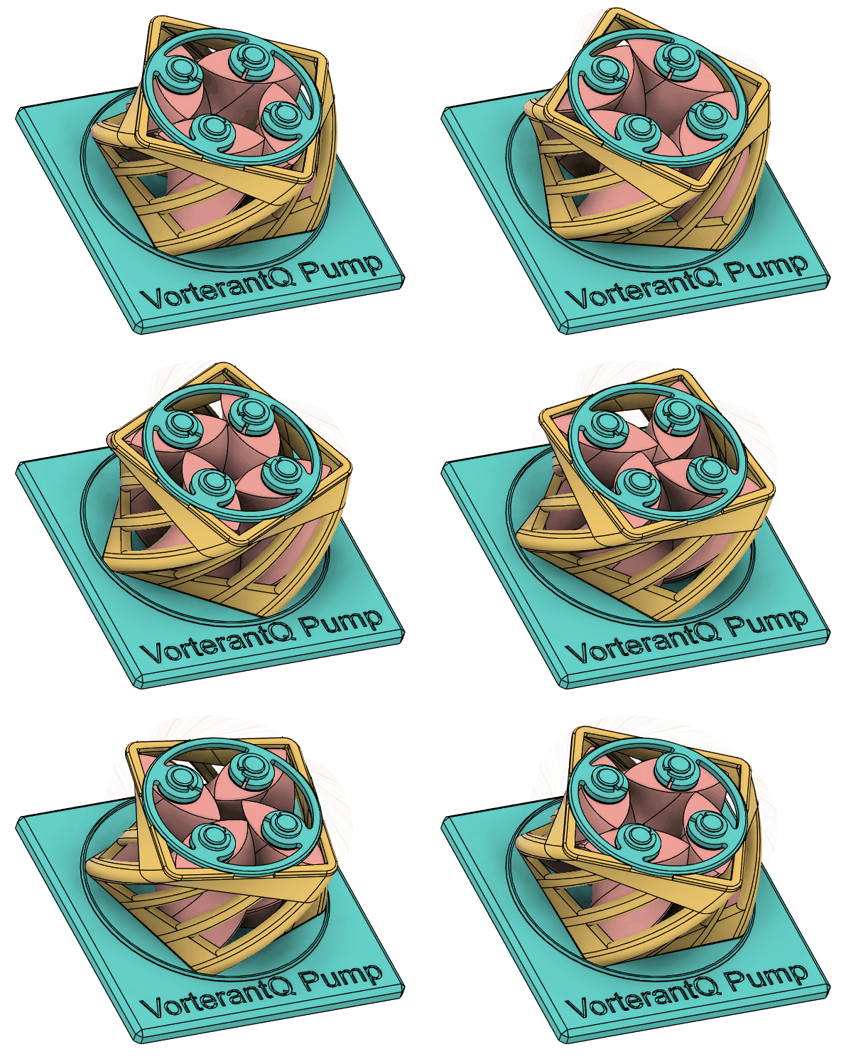
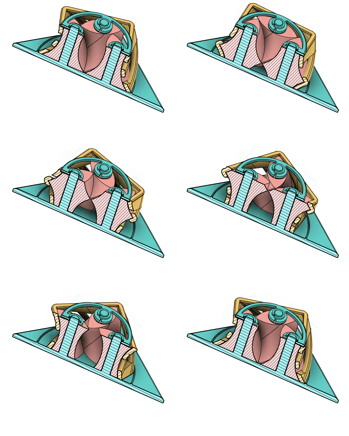
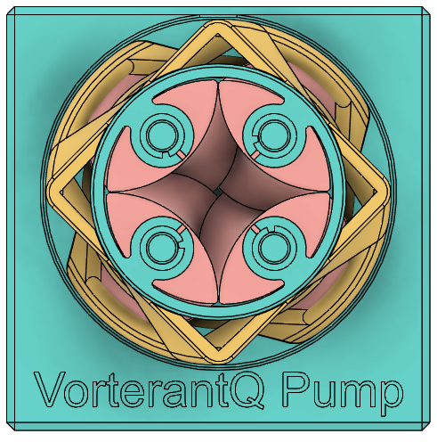
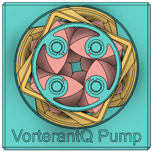
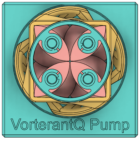
Let a denote the distance between adjacent rotational axes. Each rotor has a lens-shaped cross-section formed by two circular arcs of radius a. The distance between the two tips of a rotor is √2 a, and the width measured perpendicular to that axis is (1 − 1/√2) a. When all four rotors turn simultaneously, each rotor tip travels along the curved face of its neighbor, achieving an ideal seal. The four rotors are always inscribed within a square of side 2a that rotates at half the angular velocity of the rotors. Note that, as can be seen in the above animation gif, the tangent points between the square and the rotor always lie on the diagonal of the base plate — that is, within its particular cross-section.
The outer casing takes the form of a twisted square frame corresponding to this square, and transmits rotation to the rotors at a gear ratio of 1:2: one quarter-turn of the casing produces one half-turn of the rotors, returning the assembly to the tip-to-tip configuration. Considering a single cross-section in isolation, one might expect the drive to disengage — freewheeling — at the configuration where the rotor faces contact the midpoints of the casing's sides. However, because both the rotors and the casing are helically twisted along the axial direction, some cross-section is always in tip-to-tip engagement, and rotation is transmitted without interruption. Note that the open cutouts in the casing walls of this model are included solely for visualization purposes; in a functional pump, the casing walls would be fully enclosed.
In practice, the rotor tips must be filleted, which introduces a small void at the center where the four tips converge. Modifying the rotor face profile to mate with the filleted tips causes the casing sides to bow slightly outward rather than remaining straight.
Sealing Characteristics and Performance
Sealing is achieved by line contact between the sharp tip edge of one rotor and the gently curved face of its neighbor. As a result, the ratio of leakage flow to net delivered flow increases at low speeds with low-viscosity fluids, reducing efficiency. The pump is consequently considered best suited for displacing high-viscosity materials.
Even so, some leakage is unavoidable. High-viscosity fluid that accumulates in the space between the rotor faces and the casing wall will be churned continuously, leading to potentially significant energy loss and heat generation. Periodic flow pulsation is a further drawback of this pump type.
One approach to mitigating these difficulties is to omit the casing entirely and submerge the bare rotors directly in the source pool. Any lateral leakage simply returns to the pool, eliminating the need for additional sealing. The churning of fluid outside the rotors is expected to cause less energy loss than when the same fluid is confined to the narrow gap between the rotors and a casing wall, as the surrounding fluid is free to move rather than being forced through a restricted space. Heat generated in the process is also readily dissipated into the source pool, which acts as a thermal bath and prevents significant temperature rise. The drawback is that the casing can no longer be used to drive the rotors; an alternative means of driving their rotation — such as an external gear train — becomes necessary.
Potential for Multi-rotor Arrays
Unhoused rotors can transmit rotation directly to their neighbors — and unlike conventional external gears, adjacent rotors turn in the same direction. This makes it possible to arrange, for example, a 3×3 array of nine rotors and drive them all simultaneously, creating four pumping zones at the 2×2 internal rotor intersections. Such an arrangement reduces the ratio of dead volume within the casing to the actively pumped volume. Furthermore, because adjacent pumping zones operate in antiphase, significant reduction of flow pulsation is also expected.
Current Status
I understand that this pump type has not yet seen widespread practical deployment; the technology is currently at the stage of proof-of-concept demonstration.
References
- [https://makerworld.com/en/models/469791-vorterantq-pump](https://makerworld.com/en/models/469791-vorterantq-pump)
- [https://www.reddit.com/r/EngineeringPorn/comments/1722g1n/multi_rotor_pump_vorterant/](https://www.reddit.com/r/EngineeringPorn/comments/1722g1n/multi_rotor_pump_vorterant/)
Case
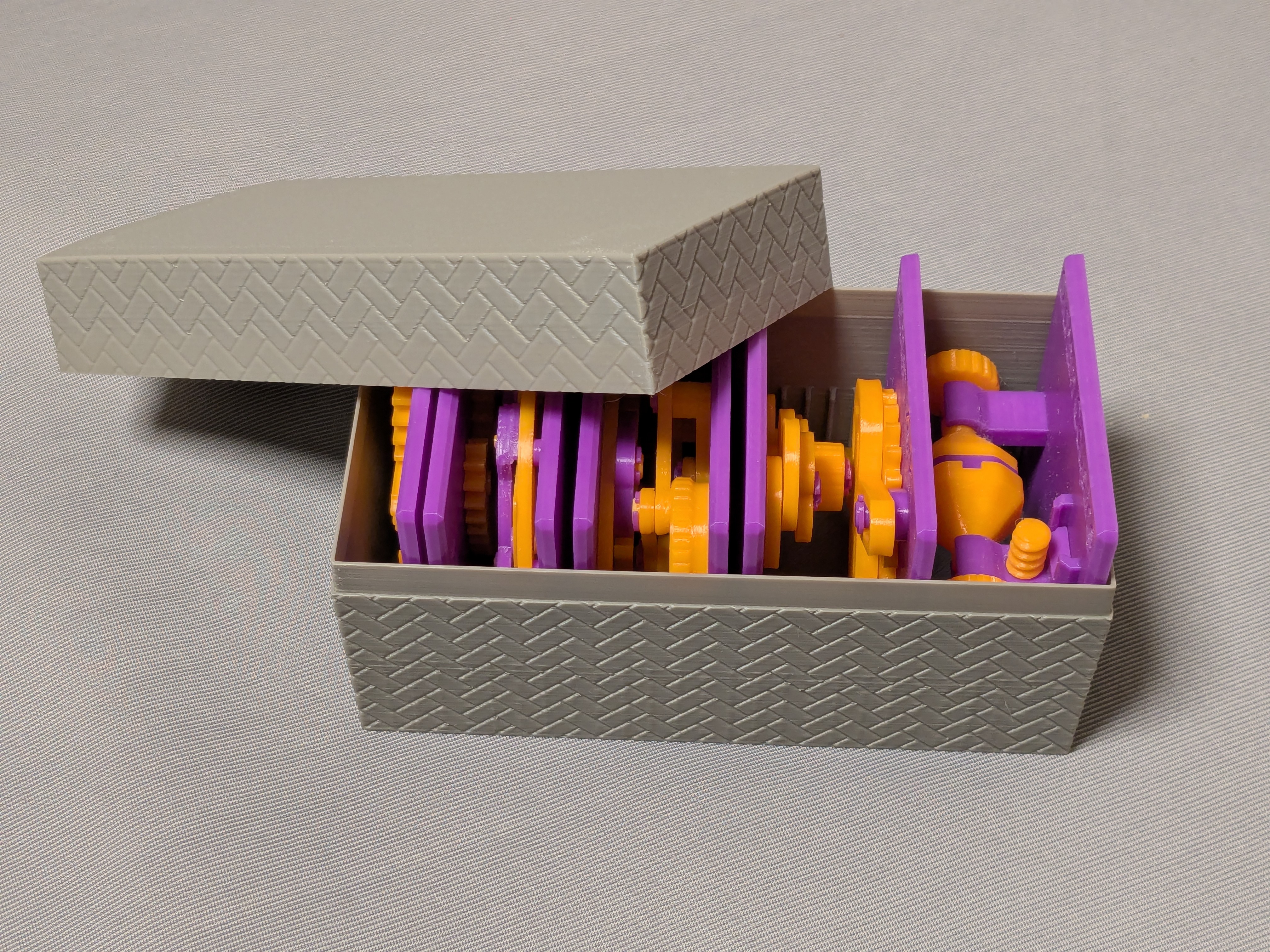
This model is compatible with the case included in my first set.
Printing
- Use the models named ???-printable.stl for printing.
The models named ???-assembled.stl are provided just to show how they should be assembled.
- Use well-dried PETG to have better dimensional accuracy.
- Use 0.1 mm or 0.08 mm layer height to have smoother surfaces and better overhang tolerance.
- Use slow printing speed for the sever overhangs.
- Select “Random” seam position to have smoother rotation.
Randomly distributed seam should be easily worn out after some wearing.Printing
Sanding and Filing
Note that, in this model, the rotation of the bases for bearings is intentionally made not too smooth.
Sometimes, the gears suffer from the stringing effect and/or elephant foot effect, resulting in a too tight fit to the shafts (they are designed with a 0.15 mm radial clearance).
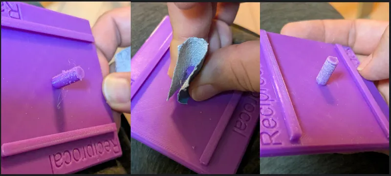
If you see rough surface on the shafts due to stringing, sand off the roughness with a small piece of sand paper.
Especially for this particular model, you need to make the inner wall of the twisted square casing smooth. Because it has sever overhangs and bridges, it surface can be printed rough. If you find roughness, file it off. If you have clean surface, the casing and the rotors should rotate super smoothly.
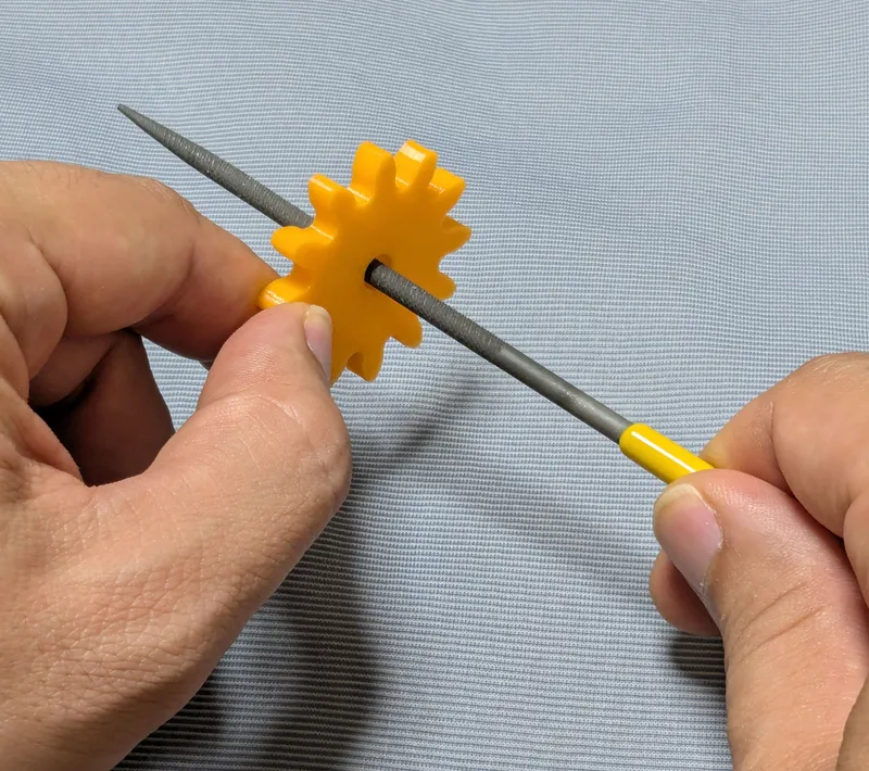
If you feel the gears do not rotate smoothly due to an elephant effect, widen the hole slightly by using a thin round bar file.
Without those issues, the parts should rotate very smoothly with minimal friction.
Assembly
Just secure the parts by the retaining rings.
Other examples
You may also be interested in the models in my educational mechanical mechanism examples.
Find them in this collection:
[https://makerworld.com/collections/15048577-my-educational-mechanism-models](https://makerworld.com/collections/15048577-my-educational-mechanism-models)
Happy printing!
Acknowledgement
I got into gears thanks to K.$uzuki's amazing articles and YouTube videos. Many of the mechanisms shown in this series came from the introductions on his website. He also makes excellent gear models himself. This series wouldn’t have existed without his inspiration.
I learned a lot about technical detail of designing gear tooth profiles from Haguruma-No-Hanashi website. I’m truly grateful for that.
License (2026-03-13 updated)
- The 3D model(s) are licensed under Creative Commons Attribution 4.0 International. (unchanged)
- However, the text and images on this page are copyright reserved. (added on 2026-03-13)
VorterantQ Pump - Educational Model

Publicado em 14 de abr de 2026
Gostou deste modelo? Crie uma conta grátis para salvar seus favoritos e voltar a eles depois.
Criar conta