Você está no 3DFinder
Buscamos em Thingiverse, MakerWorld e Printables ao mesmo tempo para te dar o melhor de cada uma.
Descrição
This sensor housing is designed to hold a GPS module, a light sensor, and a temperature/humidity sensor in a compact, weather‑aware enclosure. It was originally built for use on a boat, but the design works well in any environment where airflow and splash‑resistance are important.
The housing allows air to circulate freely around the sensors while providing drainage paths so that any water entering the enclosure can exit through dedicated holes. This helps maintain accurate readings without trapping moisture.
Design Notes
- The Main Housing has a specific print requirement:
the first two layers must be printed in clear PETG, with the remaining layers printed in any PETG colour.
This ensures the light sensor receives enough illumination while keeping the structure strong. - The enclosure is designed to be assembled once and not easily taken apart. Internal bolts secure the main housing, making it suitable for permanent or semi‑permanent installations.
- For wiring, I used 7‑core 12v trailer cable, which worked well for routing signals from the rear of a boat to the main electronics, but any multi‑core cable with suitable gauge can be used.
Bill of Materials
5m 7 core wire (or your required length)
2 x M2x5x4x3.5 Brass threaded inserts.
4 x M3x4x5 Brass threaded inserts.
2 x M4x40 bolts
4 x M4 nuts
2 x M3x16 bolts
2 x M3x6 bolts
2 x M2.5x6 bolts
2 x M6x30 bolts
2 x M8x30 bolts
2 x M8 Lock nuts
2 x M8 Washers
PETG HF Black
PETG HF Clear
PETG HF White
TPU 95A HF
Connector Strip
NEO-7M GPS Satellite Module
DHT11 Temperature/Humidity Module
Adjustable Photosensitive LDR Light Sensor Module
Assembly
The parts interlock cleanly, and the internal mounting points keep the sensors stable. Once assembled, the housing is robust and resistant to accidental disassembly. I’ll include construction photos and a full BOM to make replication easier.
Step 1
Gather all required printed parts items from BoM
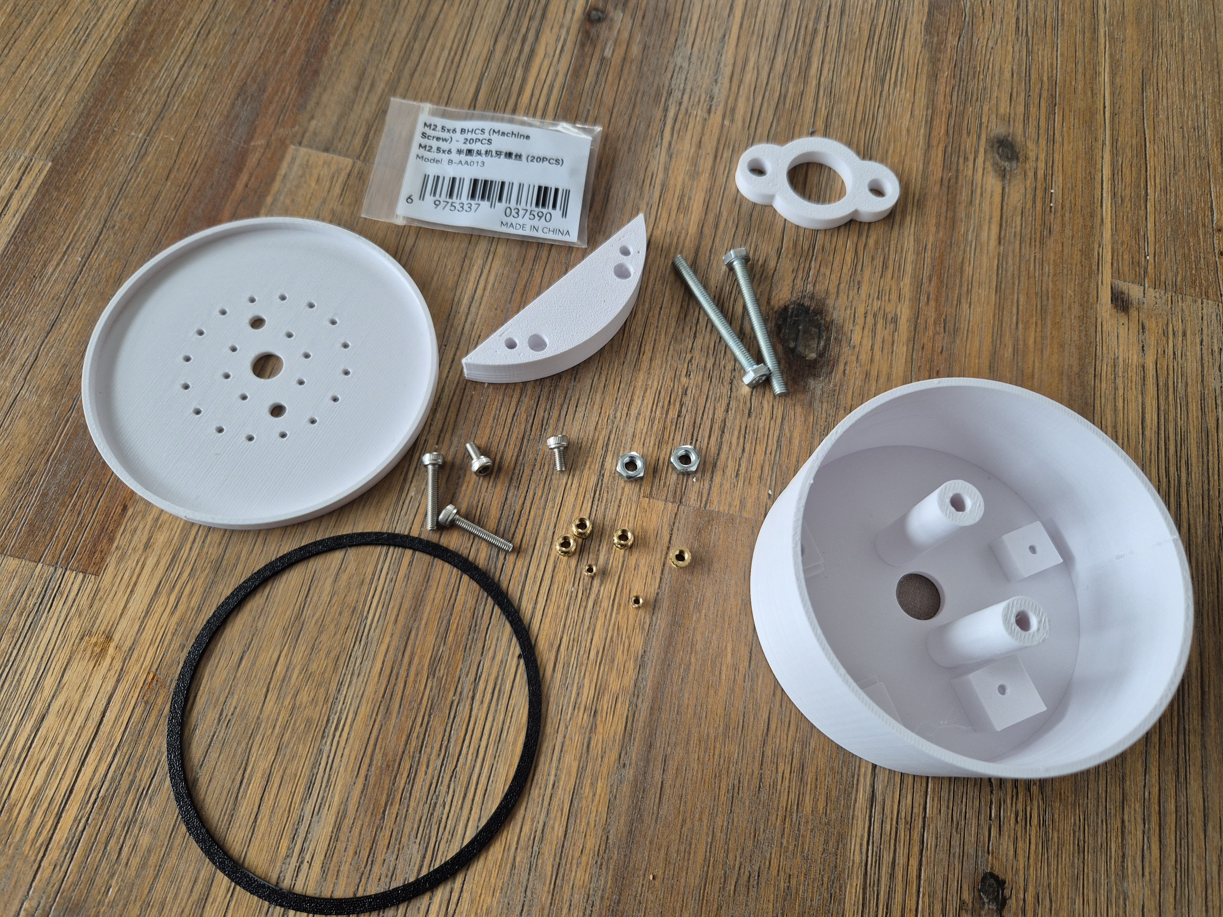
Step 2
Using a soldering iron insert the brass threaded inserts
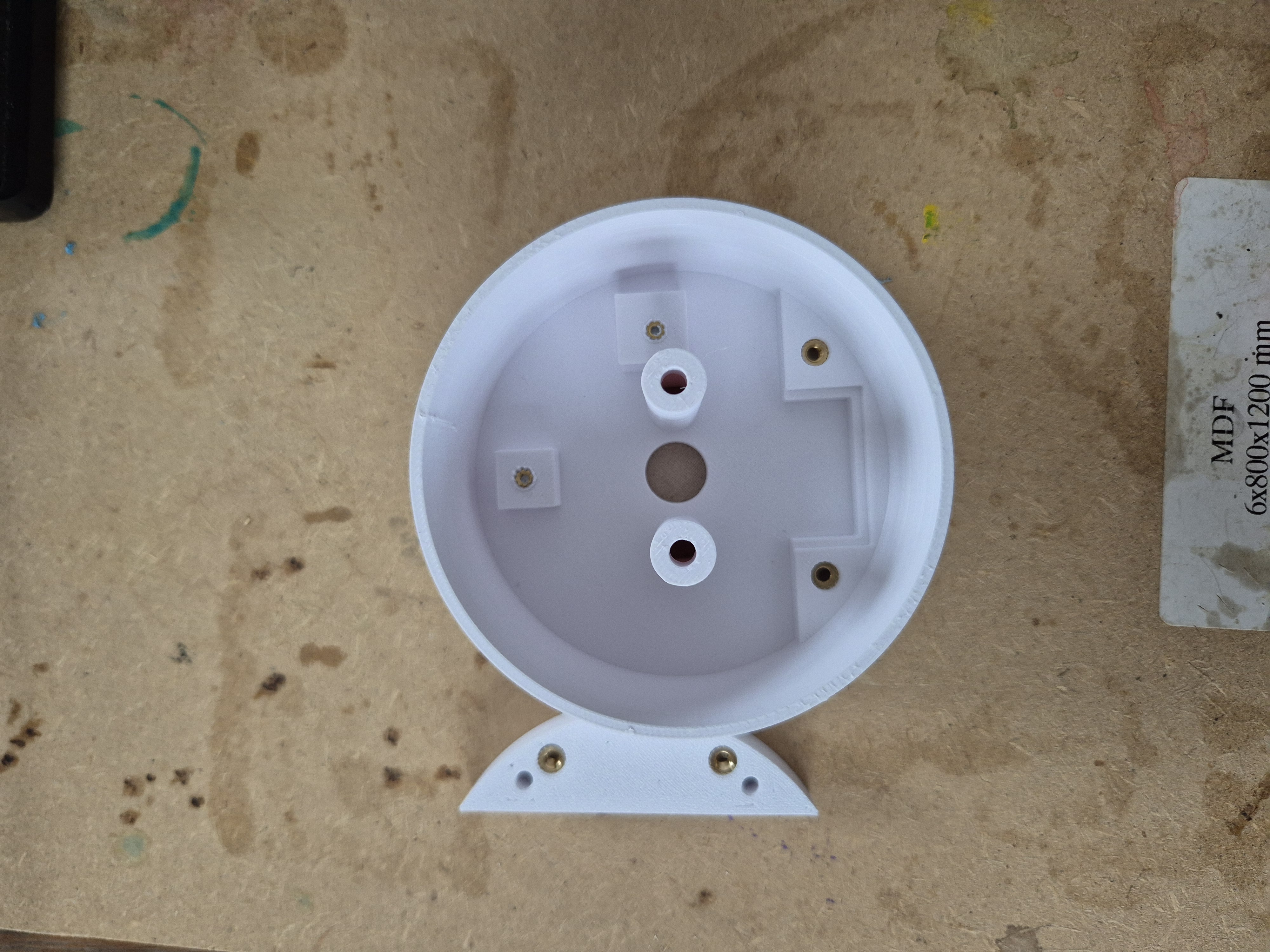
Step 3
Insert and secure the GPS module and secure
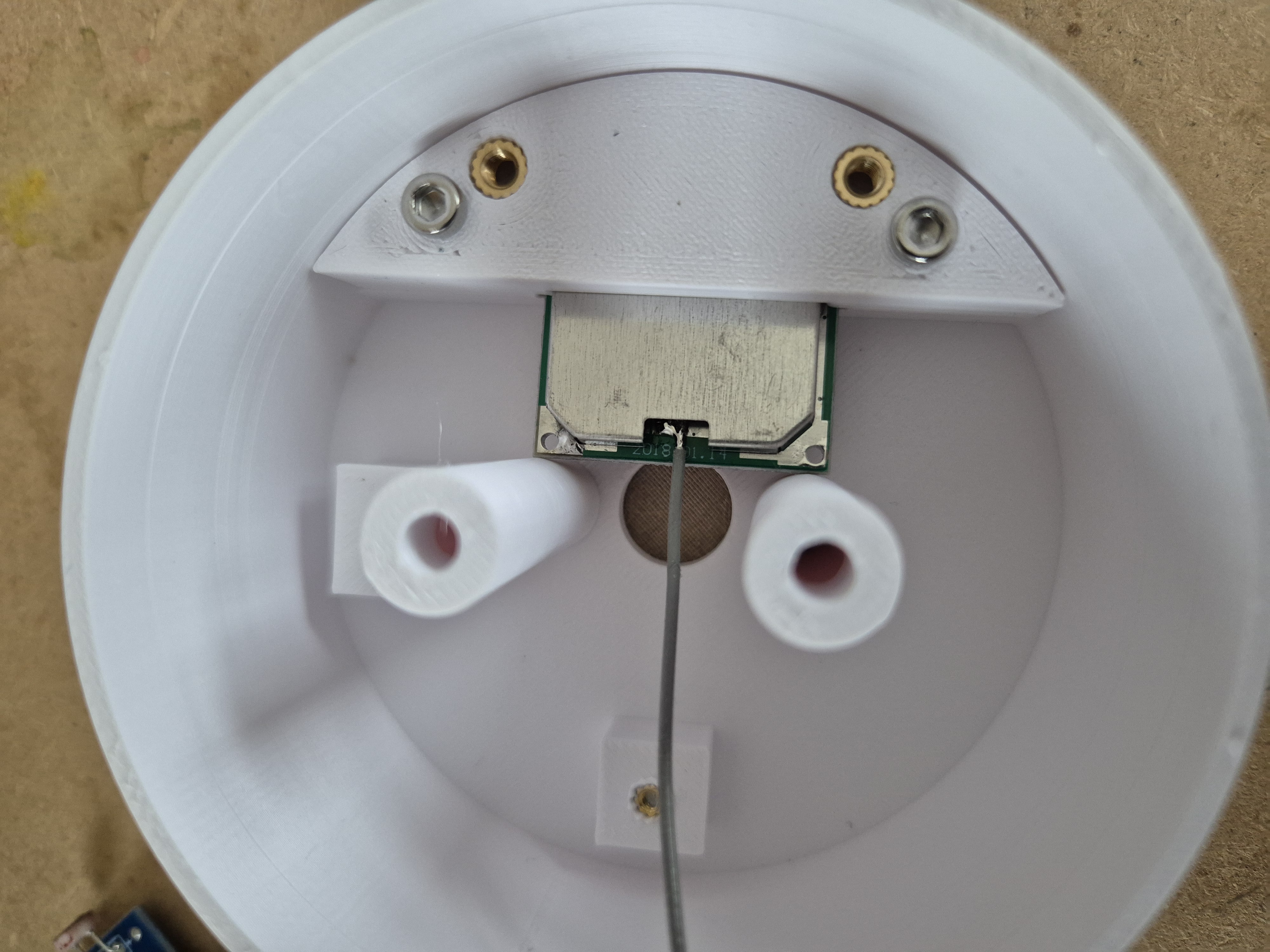
Step 4
Insert the DHT11 module and the Light sensor securing with M2.5 bolts
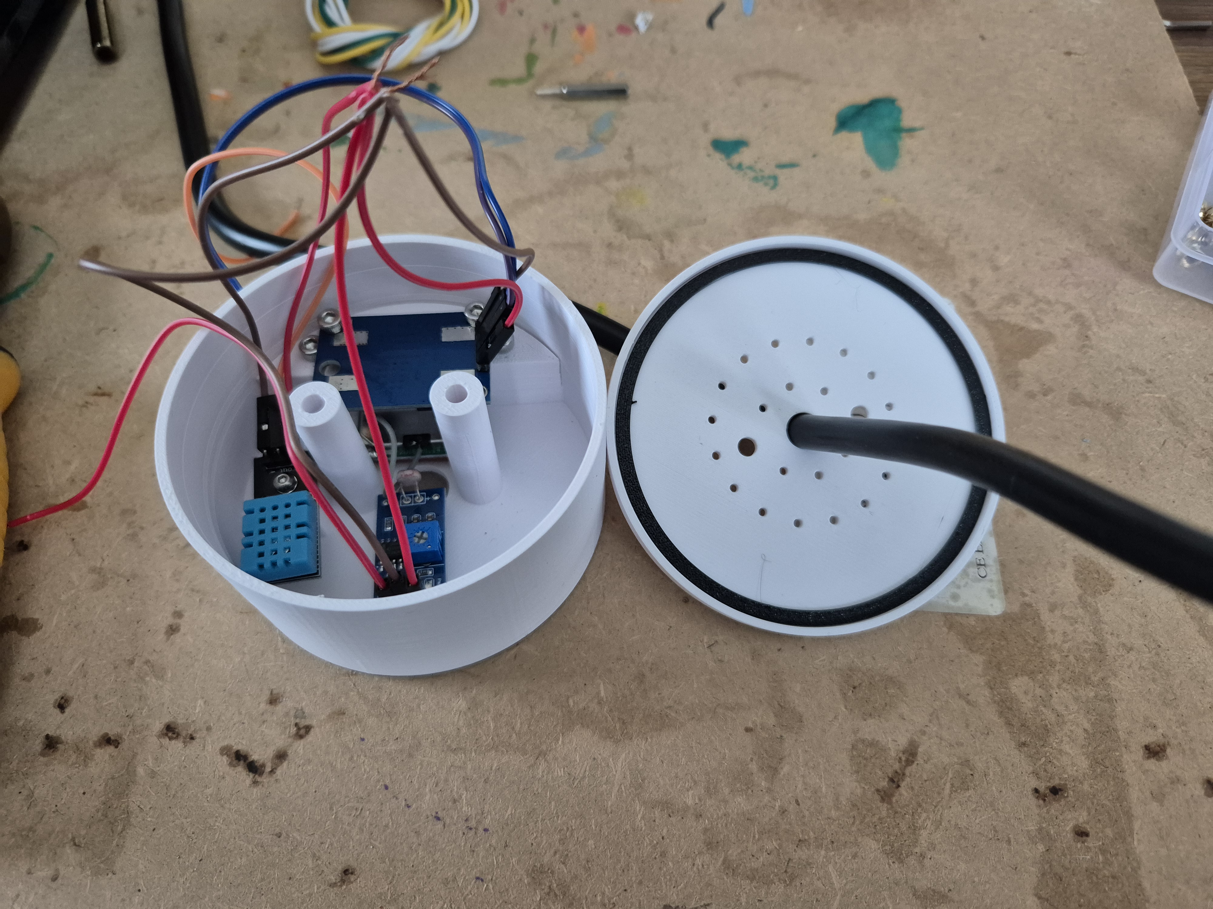
Step 5
After pushing the cable through the base and adding the TPU seal, connect your wiring
NOTE: Makes notes on wire colors !!!
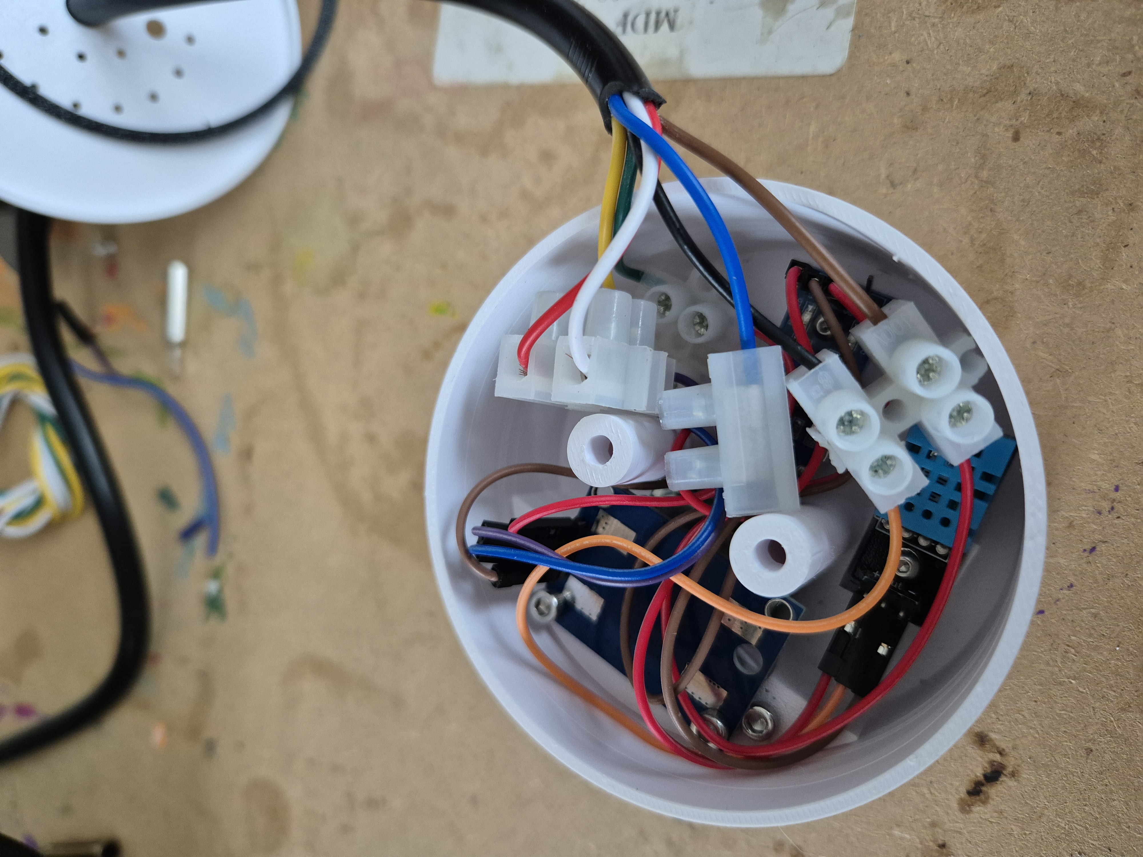
Step 6
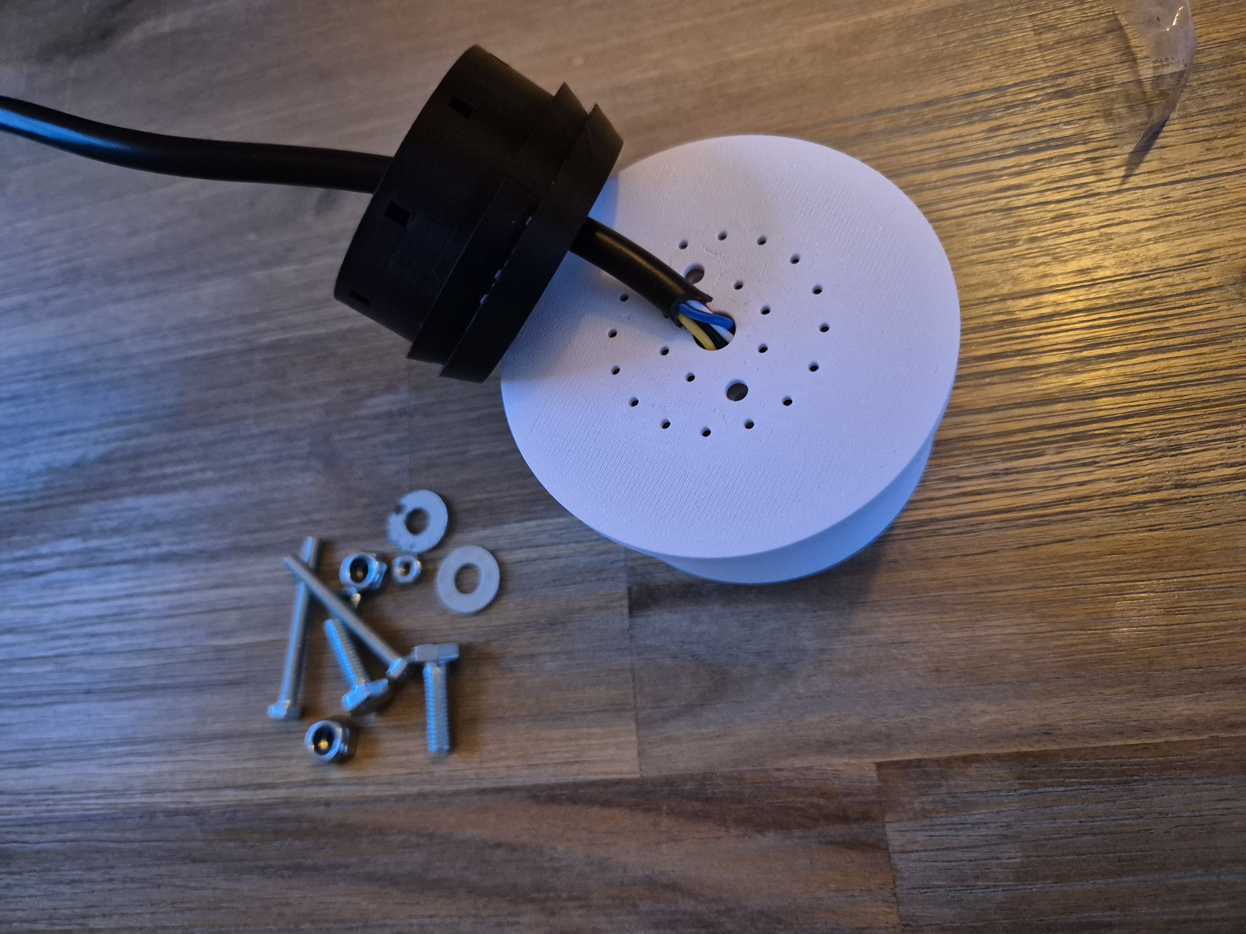
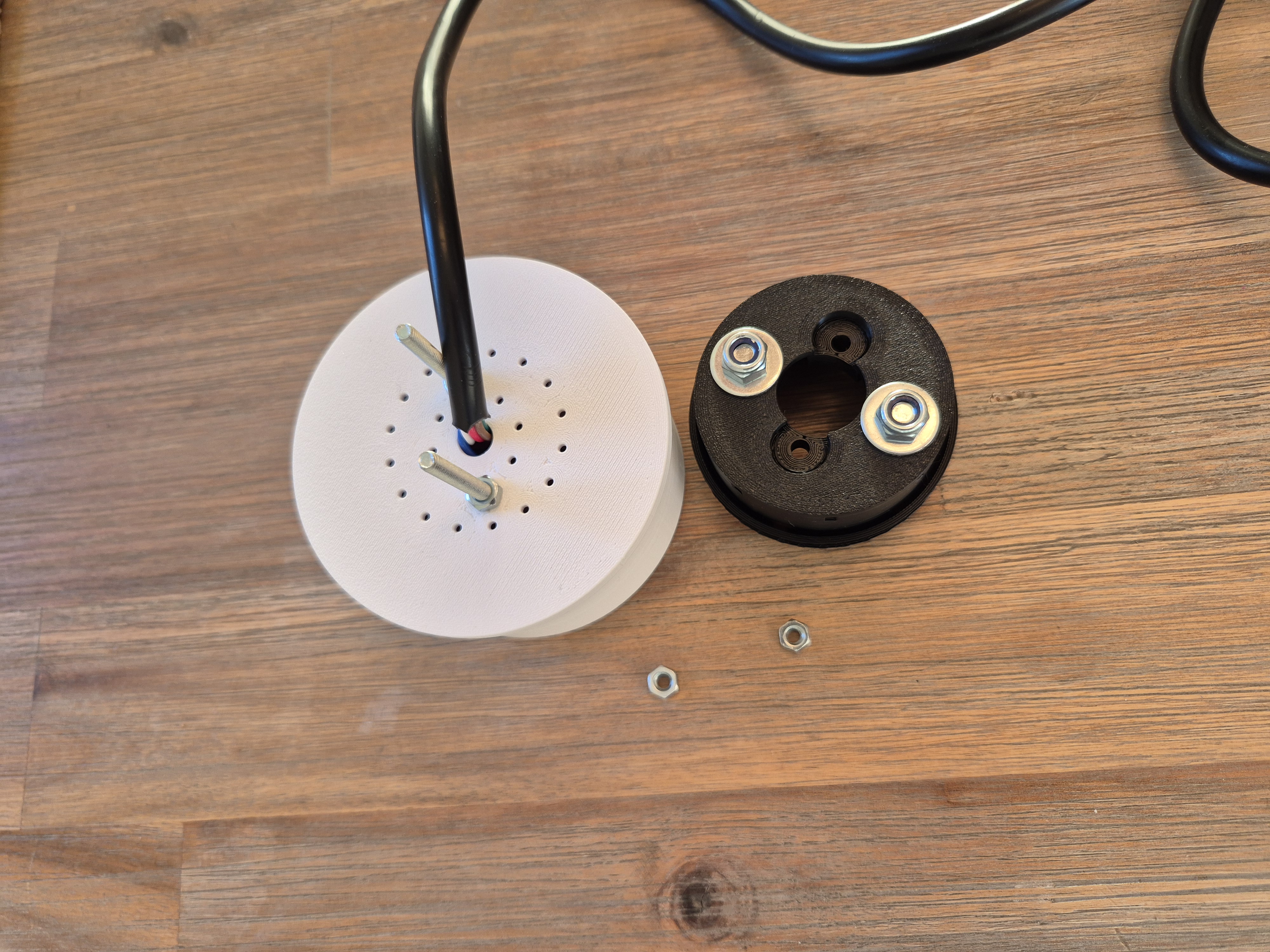
After placing the under plate on the sensor array, along with the seal, it is time to connect the base, Insert the M8 nuts into the base unit (add a little glue to stop them moving about.
Insert the M4 bolts into the white housing from the top and gently secure using M4 nuts, warning you do not need to go too tight here.
The add the bolts to the base unit.
Step 7
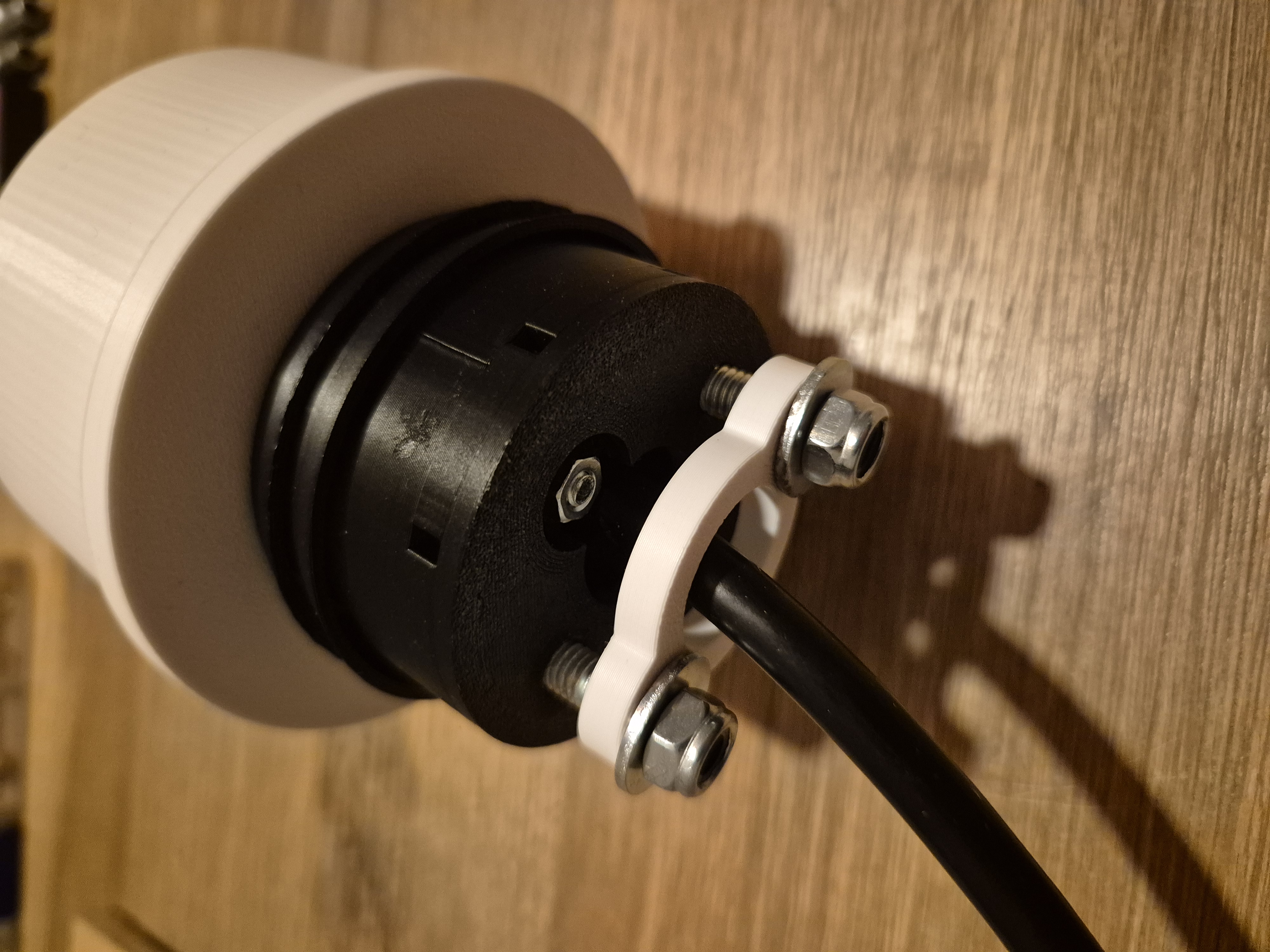
Connect the base unit to the M4 nuts and retain using 2 x M4 nuts
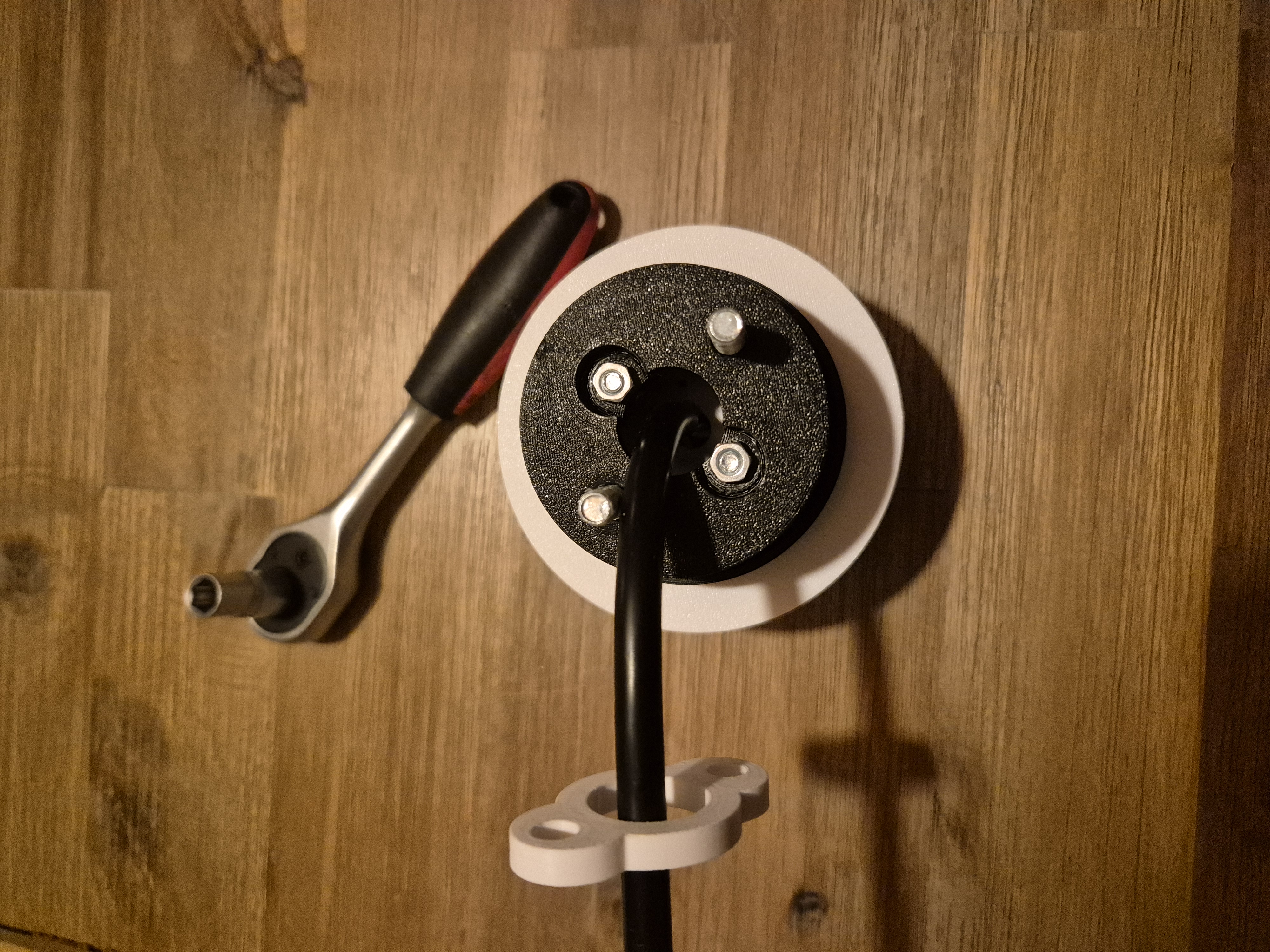
Step 8
You are now ready to install, using the base plate as a guide carefully drill the holes where it will be placed
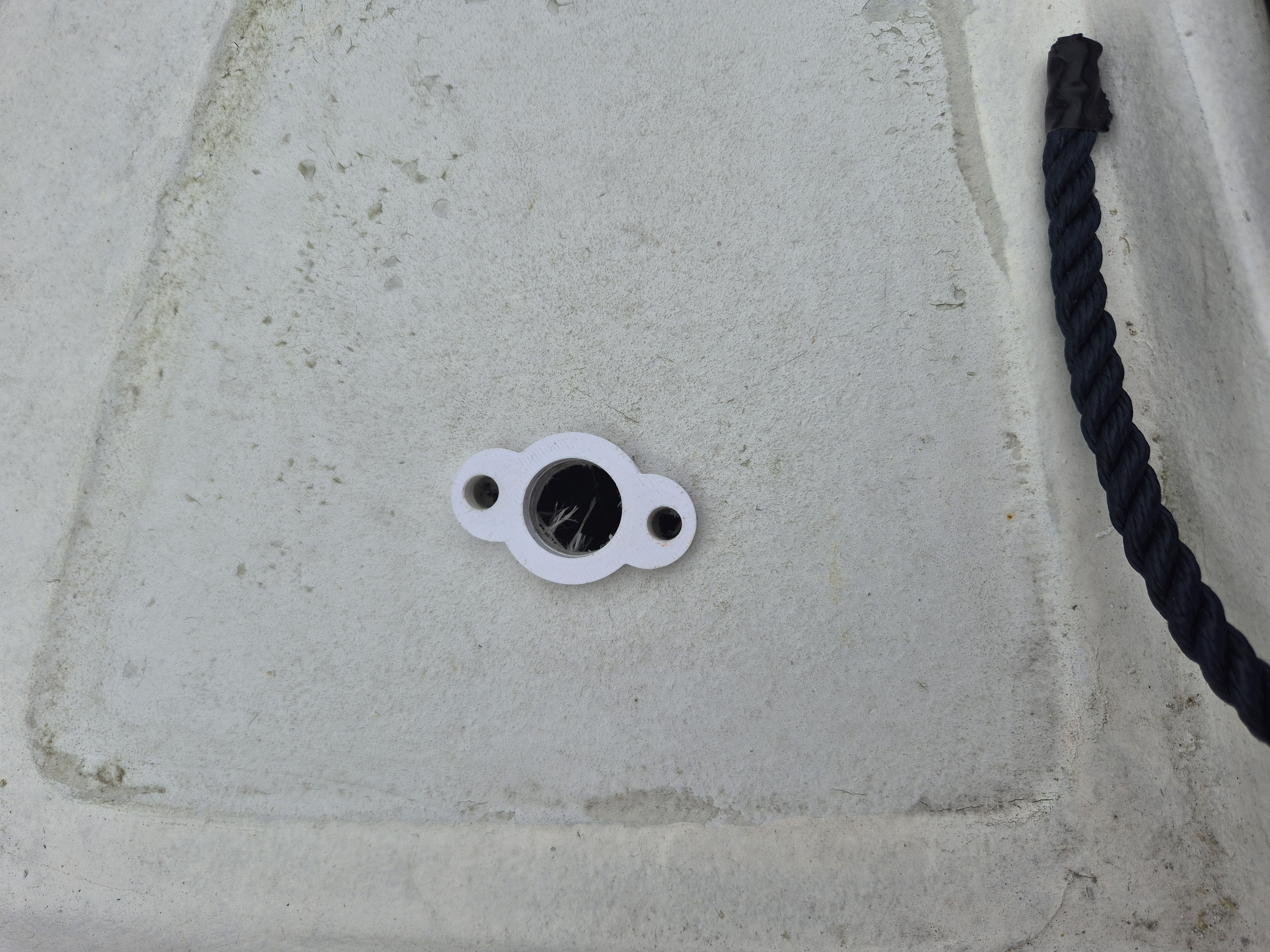
Step 9
Wire it up and you're ready to go.
Please note this was designed as part of a larger project involving a specially designed smart fuse box and boat control panel (coming soon). Although my use case was a boat, it could easily be placed in a static location on a shed etc.
If you use I hope you enjoy :-)

Gostou deste modelo? Crie uma conta grátis para salvar seus favoritos e voltar a eles depois.
Criar conta