Você está no 3DFinder
Buscamos em Thingiverse, MakerWorld e Printables ao mesmo tempo para te dar o melhor de cada uma.
Descrição
Overview
This HO Station was modeled after the La Grange Texas Station of the Missouri Kansas Texas (MKT) line. The MKT (Katy) Railroad station in La Grange, Texas, is now the home of the La Grange Depot Museum, located at 260 N Washington St. The current depot was built by the MKT in 1897 to replace an earlier one that burned down in 1897, and the building has since been preserved and adapted to serve as a museum and cultural center.
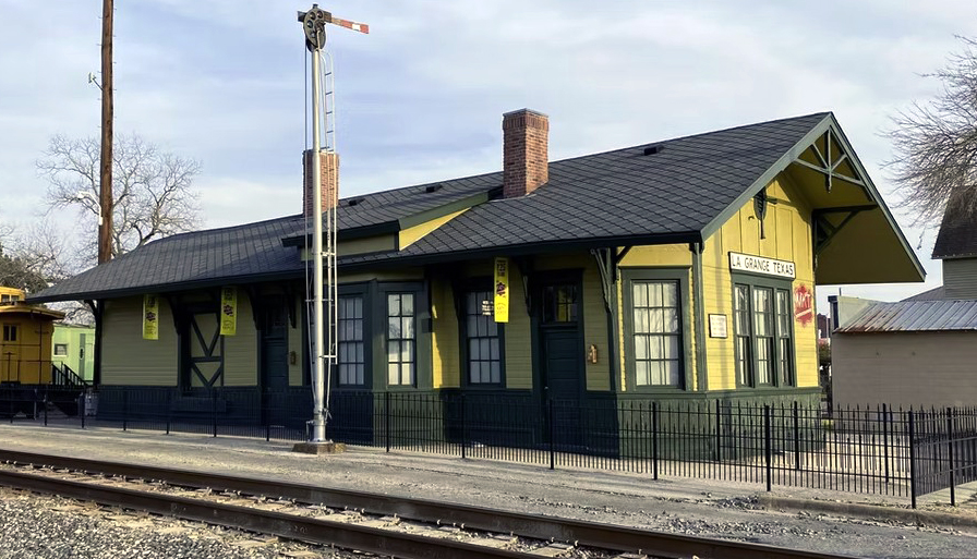
In my design I tried hard to preserve the details of the original structure.
Note: It is recommended that you assemble the station by following the order of the sections below. Otherwise, some parts may be very difficult to install.
Note: An 0.2mm nozzle is required to get the necessary resolution!
I used WeldOn 3 glue with a syringe to glue the parts together. WeldOn 3 is VERY fluid solvent, wicking down parts very quickly. When applying the glue, hold the part in an orientation that will allow the glue to wick down along the target edge. The glue works very quickly. For most parts you will only need to hold them in position for 10-20 seconds. This glue can also damage the paint on a table, so apply the glue over a sheet of cardboard.
Preparation
NOTE: Ensure that all pieces fit before gluing.
Station Walls
Take a moment to clean up the edges of the all the parts. There may be a little sagging of the plastic due to bridging or supports.
Assembly
The following illustrations walk through the assembly process for the Train Station.
Roof
The roof is installed as 3 sections then 2 braces are added.
The Rear Lower Roof is installed first. It rests on top of the rear and side wall, and the Station Back Lower Wall Section aligns with the wall as indicated by the blue arrow. The green arrows in Figure 1 show how the roof should be placed. Run a bead of glue along the top of the back and side wall before installing the roof section.
Figure 1: Rear Lower Roof Installation
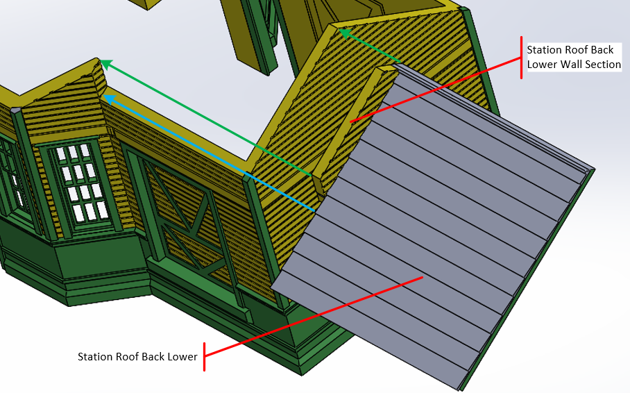
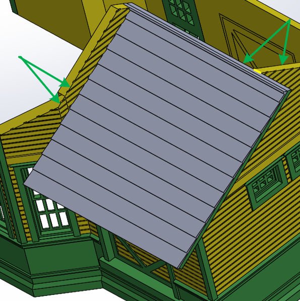
Figure 2 shows the position of the Lower Rear Roof after installation. Note that the edge of the ‘Lower Rear Roof Wall Section’ should be flush with the Station Wall, as shown by the 2 green arrows on the left. And the edge of the right side of the roof should be flush with the front edge peak (short yellow line) of the Station Wall, as shown by the 2 green arrows on the right.
Figure 2: Rear Lower Roof Installed
The Front Roof is installed next. It rests on top of the front and side walls, and against the right side of the Rear Lower Roof (in Figure 3). The green arrows in Figure 3 show how the window should be placed. Run a bead of glue along the top of the front and side walls and the right side of the Rear Lower Roof before installing the Front Roof section.
Figure 3: Front Roof Installation
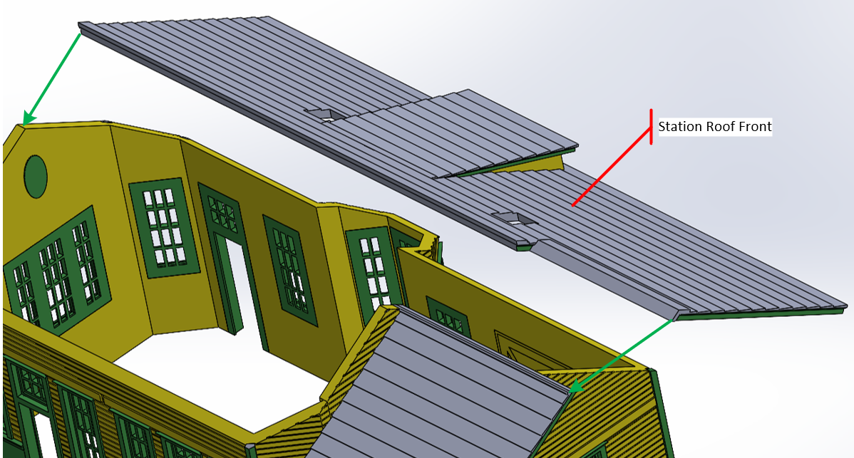
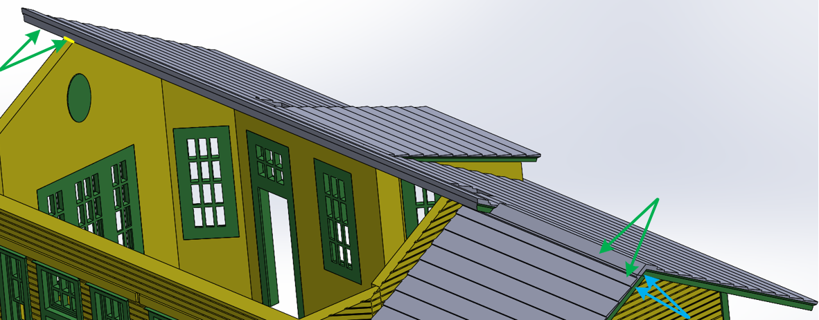
Figure 4 shows the position of the Front roof after installation. Note that the rear edge of the Front roof should align with peak (i.e., the short yellow line on left side) of the far wall, as shown by the 2 green arrows on the left. And the edge of the roof top should be flush with the corresponding top edge on the Rear Lower Roof, as shown by the 2 green arrows on the right. And the right side of the Front roof should be flush with the right side of the Rear Lower Roof, as shown by the 2 blue arrows on the right.
Figure 4: Front Roof Installed
Now the Rear Upper Roof is installed. It rests on top of the rear and side walls, left side of the Read Lower Roof (in Figure 5). The green arrows in Figure 5 show how the Upper Rear Roof should be placed. Run a bead of glue along the top of the rear wall, the far side wall, the short wall section that is part of the Lower Rear Roof, and the inside of the peak of the Upper Rear Roof, where it meets the Front Roof peak, before installing the roof section.
Figure 5: Rear Upper Roof Installation
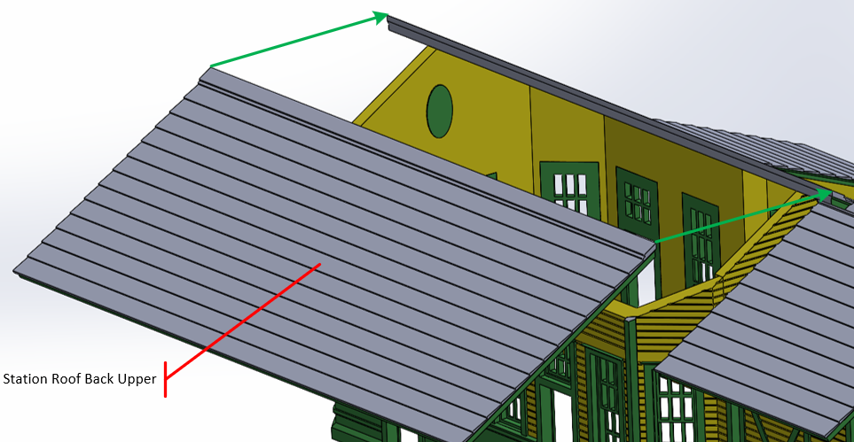
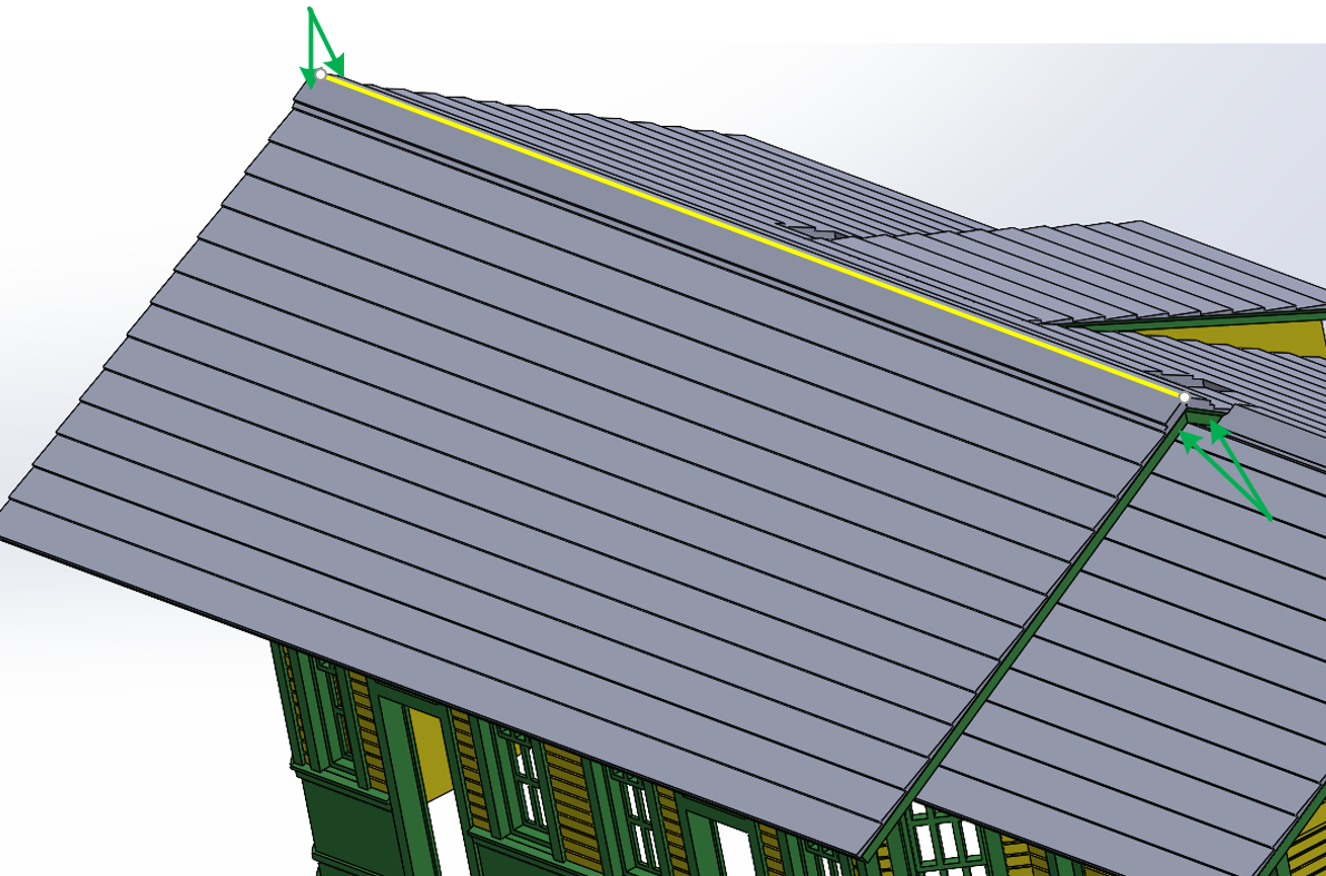
Figure 6 shows the position of the Rear Upper Roof after installation. Note that the front edge of the roof should align with peak (i.e., the long yellow line) of the Front Roof, as shown by the 2 green arrows on the left. And the right side of the Rear Upper Roof should be flush with the right edge of the Front Roof, as shown by the 2 green arrows on the right.
Figure 6: Rear Upper Installed
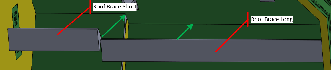
Finally install the Roof Braces. The roof braces fit under the two peaks of the roof. Run a bead of glue along both sides of the top of the Roof Braces, then press them into the peaks of the respective roof sections. Refer to Figure 7.
Figure 7: Roof Brace Installation
When installed, the Roof Braces should fit tightly against the peak of the roofs, as shown in Figure 8.
Figure 8: Roof Brace Installed
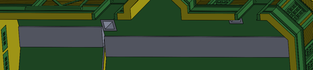
Chimneys
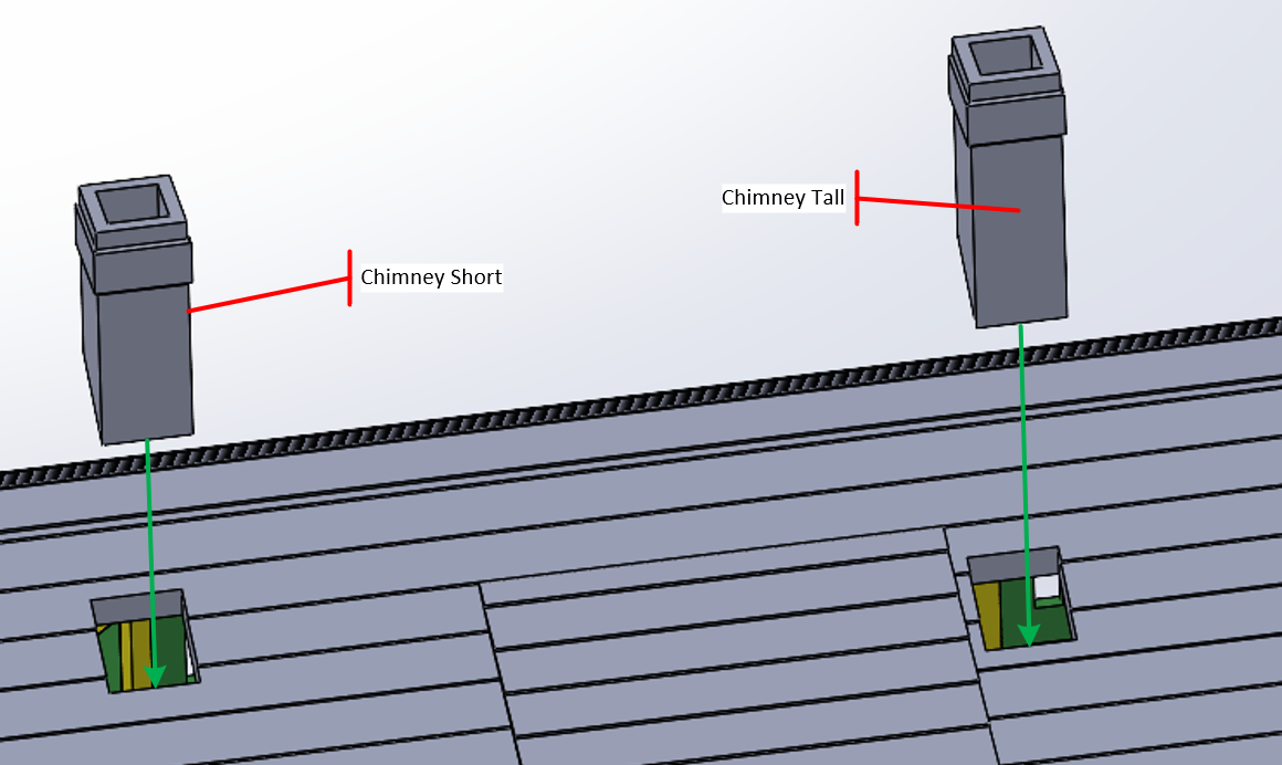
The two chimneys are pressed in place, then glued.
Note that there is a Short and a Tall Chimney. Looking at the station from the front, the Short Chimney is fitted to the left hole in the Front Roof, and the Tall Chimney is fitted to the Right hole in the Front Roof.
If properly installed, the bottoms of the chimneys should be flush with the inside surface of the Front Roof. After fitting the chimneys, run a bead of glue around the inside of it joint between the chimney and Front Roof from the bottom.
Figure 9: Chimney Installation
30 Degree Roof Braces
There are 12 30 Degree Roof Braces that are glued into place.
Figure 10 shows how the 7 30 Degree Roof Braces on the front of the station are positioned (green arrows). The braces on the far right and left are centered on their respective green trim sections, while the remaining 5 braces are position in small vertical slots that are in the crown board on the wall of the station. Refer to Figure 10.
Run a bead of glue along the top and vertical sides of the “Roof Brace 30 Degree.STL” parts then press them into position until the glue cures.
Figure 10: Front 30 Degree Roof Braces
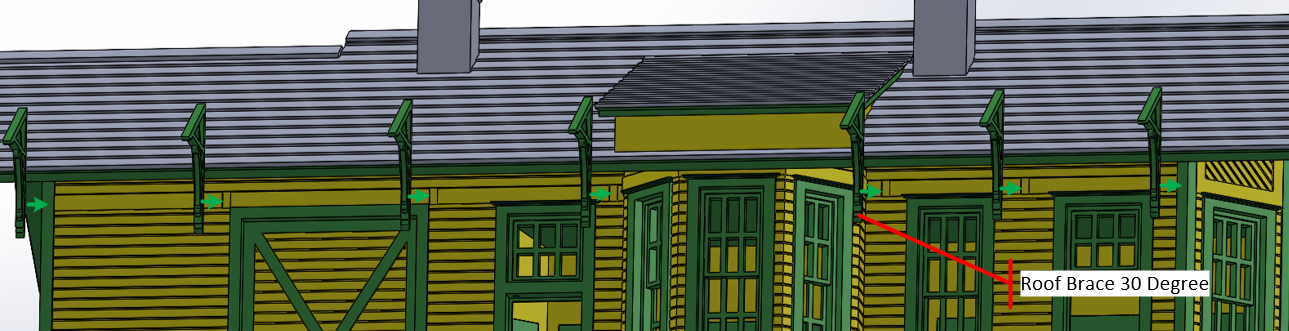
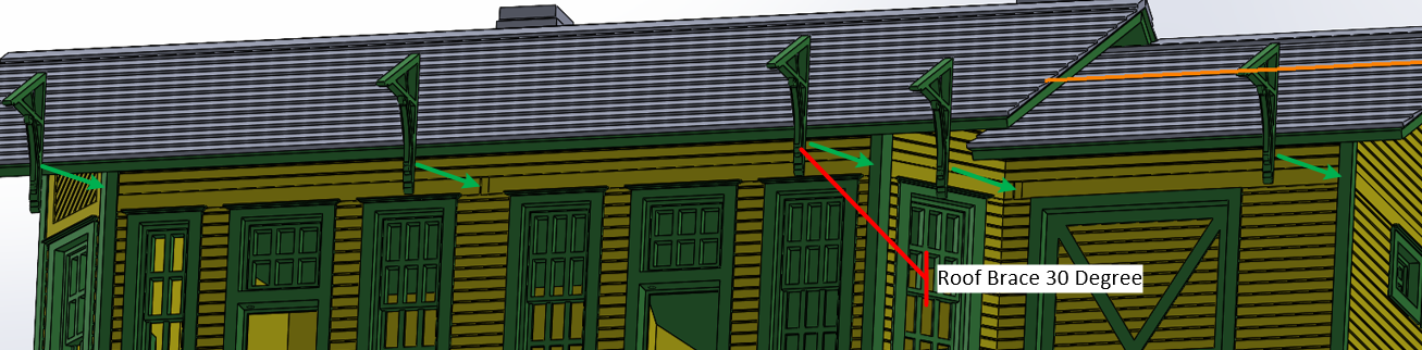
Figure 11 shows how the 5 30 Degree Roof Braces on the back of the station are positioned (green arrows). The 3 braces on the far right, left, and center are centered on their respective green trim sections, while the remaining 2 braces are position in small vertical slots that are in the crown board on the wall of the station. Refer to Figure 11.
Run a bead of glue along the top and vertical sides of the “Roof Brace 30 Degree.STL” parts then press them into position until the glue cures.
Figure 11: Rear 30 Degree Roof Braces
Side Wall Roof Braces
There are 2 90 Degree Corner Roof Braces that are glued into place.
Figure 12 shows how the Right and Left 90 Degree Corner Roof Braces on the right end of the station are positioned (green arrows). The braces are centered on their respective green trim sections. Refer to Figure 12: Corner 90 Degree Roof Brace. Look carefully at the Braces to determine which one is the Left vs. the Right.
Run a bead of glue along the top and vertical sides of the Roof Braces then press them into position until the glue cures.
Note the horizontal and vertical accents of the oval end vent in the wall (shown in Figures 12-15) are too small to be rendered with an 0.2 nozzle.
Figure 12: Corner 90 Degree Roof Brace Installation
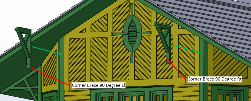
Figure 13 shows the Corner Roof Braces properly installed.
Figure 13: Corner 90 Degree Roof Braces Installed
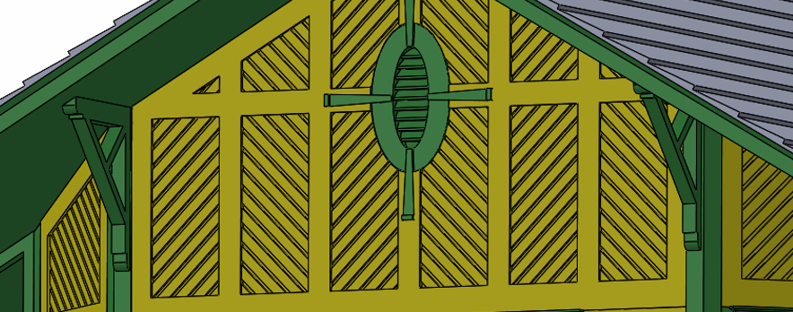
Figure 14 shows how the Side Roof Brace the end of the station is positioned (green arrow).
Run a bead of glue along the top sides of the Side Roof Brace.STL, then press it into position until the glue cures.
Figure 14: Side Roof Brace Installation
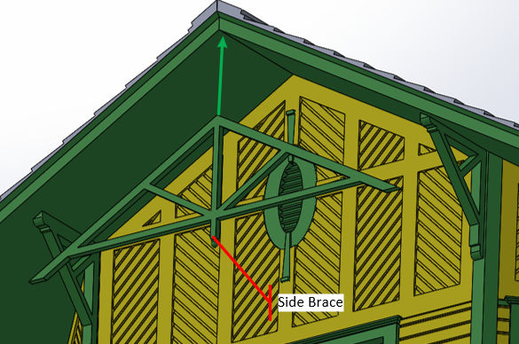
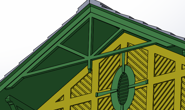
Figure 15 shows the Side Brace properly installed. Note that it is offset slightly in from the end of roof.
Figure 15: Side Roof Brace Installation
Install the Side Roof Brace on the opposite side of the station.
Final Assembly
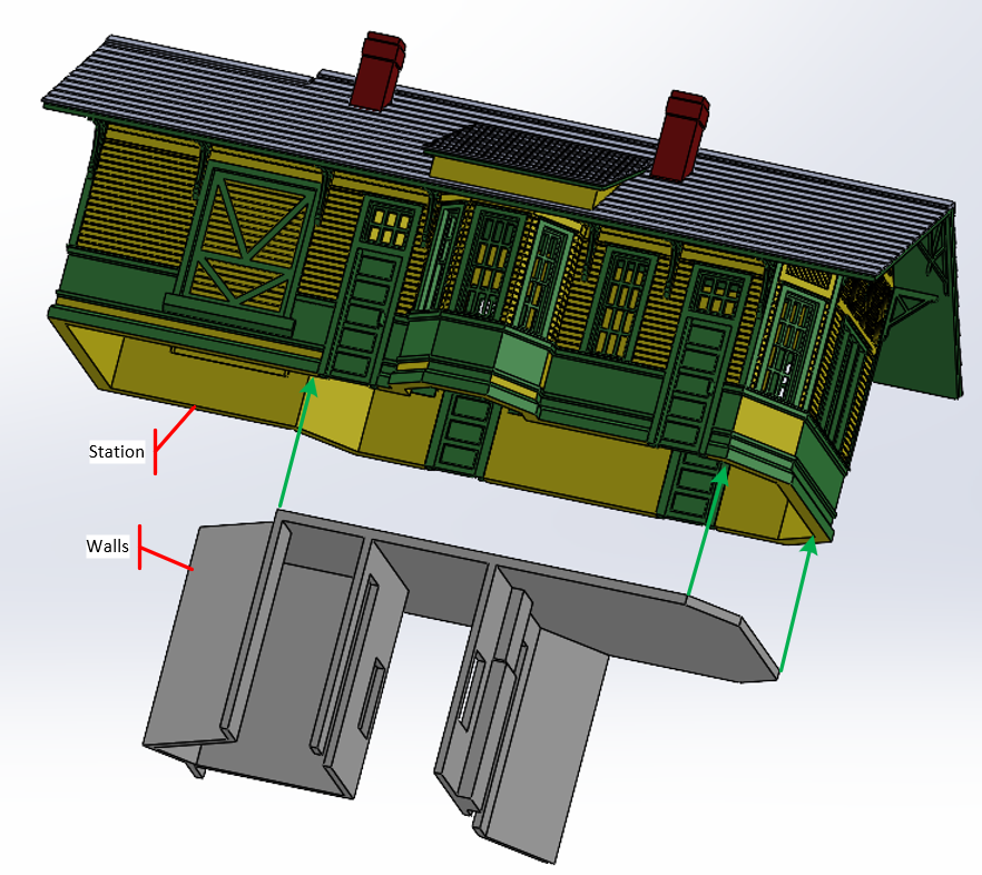
The use of these Interior Walls and Floor parts is optional.
The Interior Walls part allows individual rooms in the station to be lit. To do this, you will need to drill holes in the ceilings of the Interior Walls part and wire lights, so if you plan to light the station, install the lighting before you glue the walls into place.
To install the walls press the part against the roof. No need to glue them if you are going to install the Floor.
Figure 16: Door and Base installation
To install the Floor, press it against the bottom of the walls. The bottom of the floor part should be flush with the bottom of the Station. Once in position, glue along the edges.
Figure 17: Floor Installation
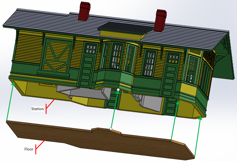
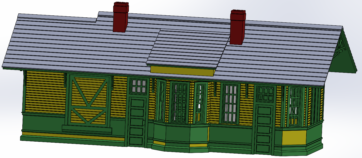
Figure 18: Final Build
Gostou deste modelo? Crie uma conta grátis para salvar seus favoritos e voltar a eles depois.
Criar conta