Você está no 3DFinder
Buscamos em Thingiverse, MakerWorld e Printables ao mesmo tempo para te dar o melhor de cada uma.
Descrição
This design features a folding utility knife with a complex internal architecture, integrating a Hawk-lock mechanism and an assisted-opening system.
Mechanical Logic: The system is centered on a power-reserve spring. Upon engaging the flipper tab, the spring begins to compress and store potential energy. Once the blade reaches a rotation angle of approximately 60 degrees, the stored tension is released, driving the blade to a fully deployed and locked position.
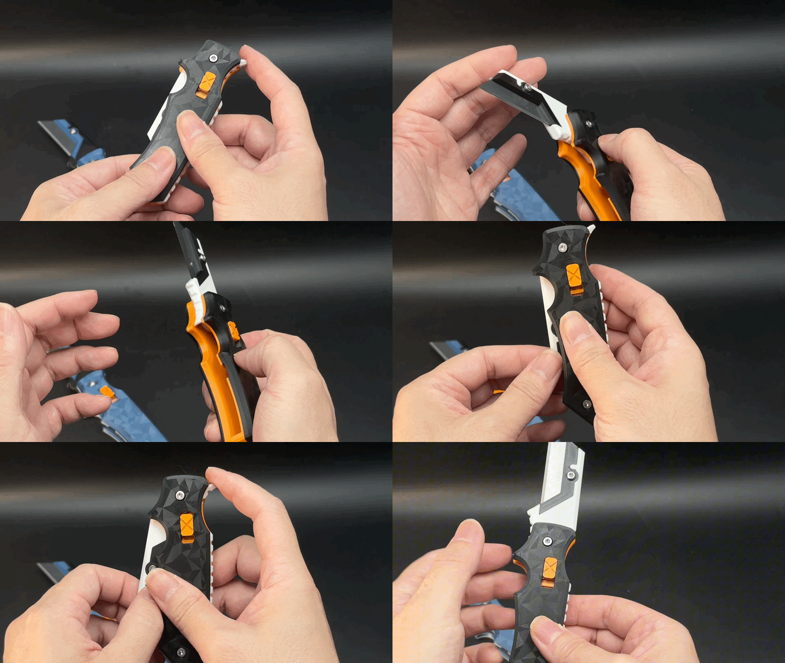
Durability & Material Science: A key engineering consideration was the material creep common in 3D-printed polymers. To mitigate this, the internal springs are designed to remain in a low-stress state when the knife is either fully closed or fully locked. Significant deformation occurs only during the brief opening transition, ensuring long-term reliability of the printed parts.
Layout: The internal systems are partitioned within the handle scales: the left side houses the Hawk-lock mechanism, while the right side contains the assisted-opening assembly. This is my most refined mechanical design of the past few months.
Technical Specifications
- Printability: Straightforward geometry; no supports required.
- Hardware: * 2 x M3-18mm screws
- 2 x M3 nuts
- 1 x M3-6mm screw & nut (for blade retention)
- Blade Compatibility: Standard Stanley Utility Blades (Model: 11-921H-22). These are globally available and easily replaceable.
Material Recommendation: This model was developed and tested using PETG. I cannot guarantee optimal spring tension with other materials (e.g., PLA or ABS). If you choose to print the body in a different material, I strongly recommend printing the spring components in PETG to maintain the intended mechanical properties.
Project Updates
1. Added Configuration: Designer’s Reinforced Edition
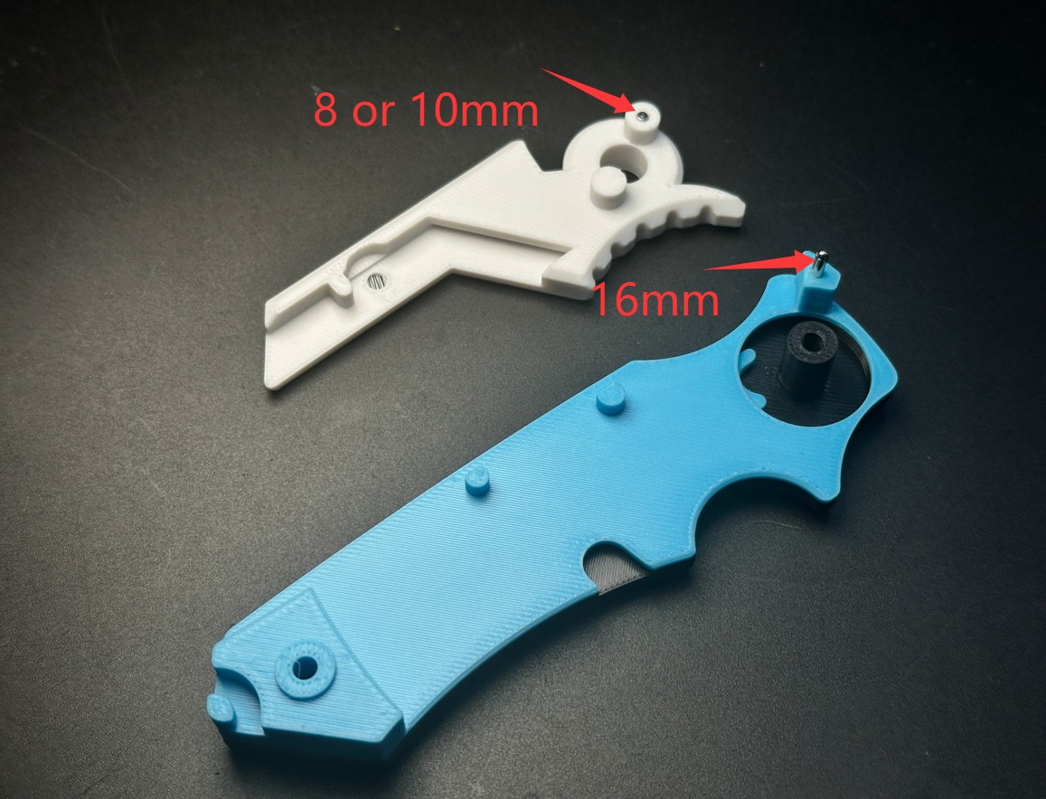
This version incorporates two metal pins into the base design to significantly enhance locking strength and the structural integrity of the stop pin.
- Requirements: 2 x 2mm diameter metal pins.
- Required Lengths: 10mm and 16mm.
The modeled diameter for the pin holes is 2.3mm. Under ideal conditions, this provides ample clearance for standard 2mm+/- 0.01mm pins.
However, some users have reported a very tight fit, making pin insertion difficult. I suspect these assembly challenges are likely caused by over-extrusion or the "elephant’s foot" effect on the initial layers, which can slightly constrict the hole's opening.
Recommendation: If you encounter significant resistance, you may need to use a 2mm drill bit to manually clear the holes for a smoother fit. This step may not be necessary if your printer’s tolerances are well-calibrated.
2. Added Configuration: Protective Storage Case
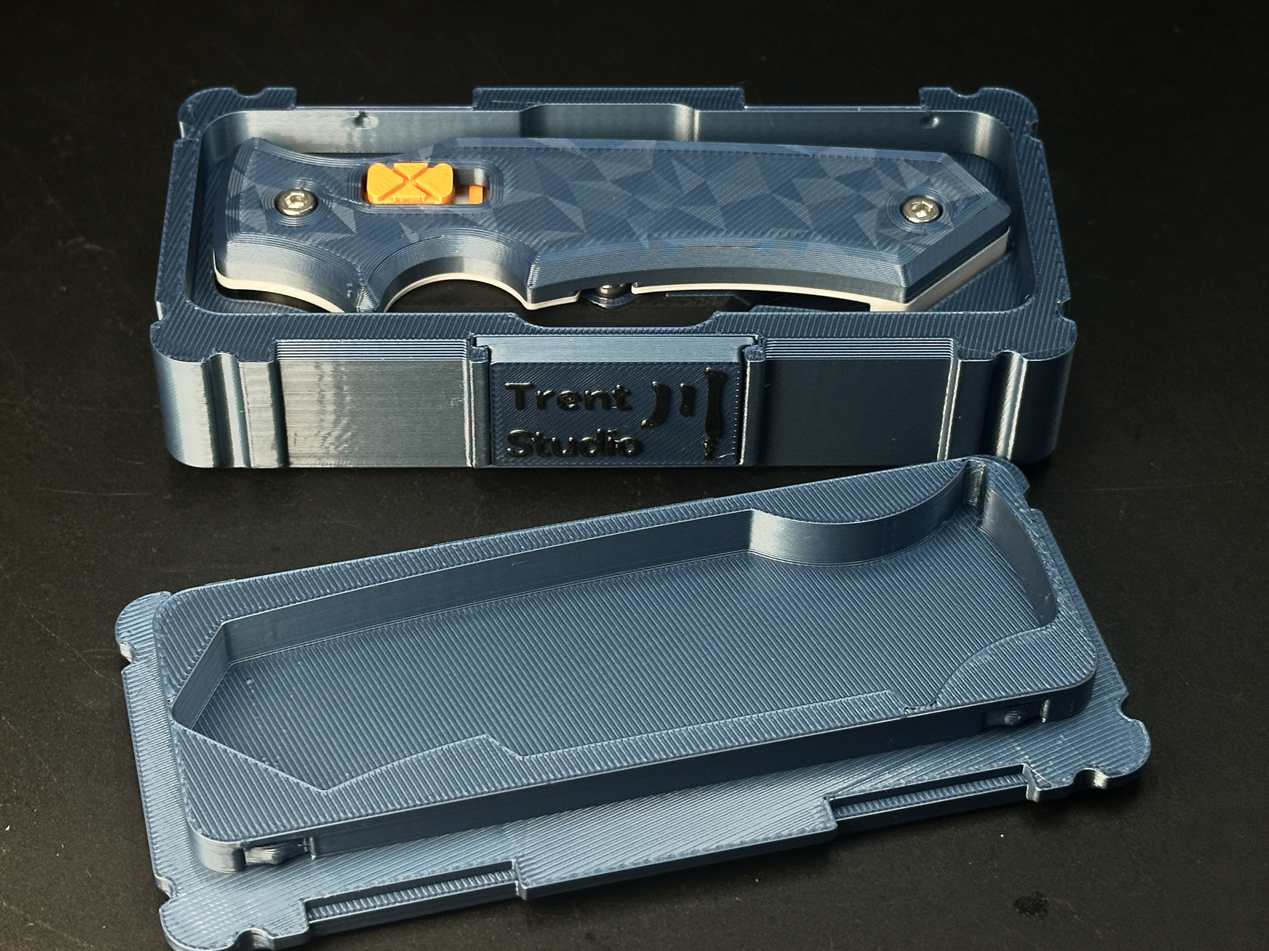
A dedicated storage case is now available. The lid features an integrated elastic tension clip for secure closure. Two nameplate options are included:
- Branded Version: Features my personal logo.
- Blank Version: Provided for customization. If you intend to give this as a gift, you can use your slicing software’s text tool to design a custom nameplate.
Assembly Instructions
It is highly recommended to watch the assembly video before proceeding.
1.Parts Overview: Lay out all printed components and hardware.
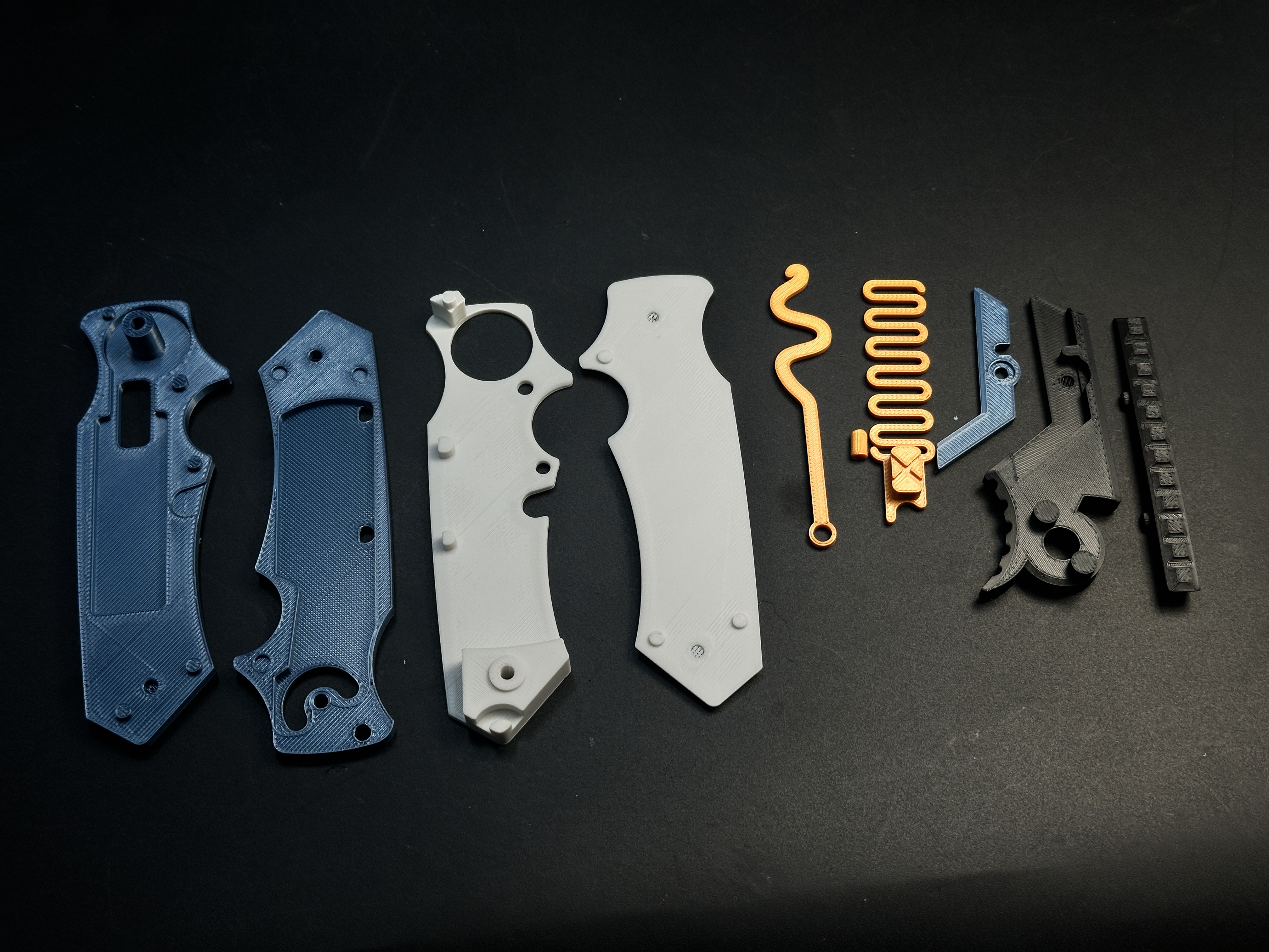
2.Locking Mechanism: Insert the locking spring into the designated recess of the left handle scale (Blue).
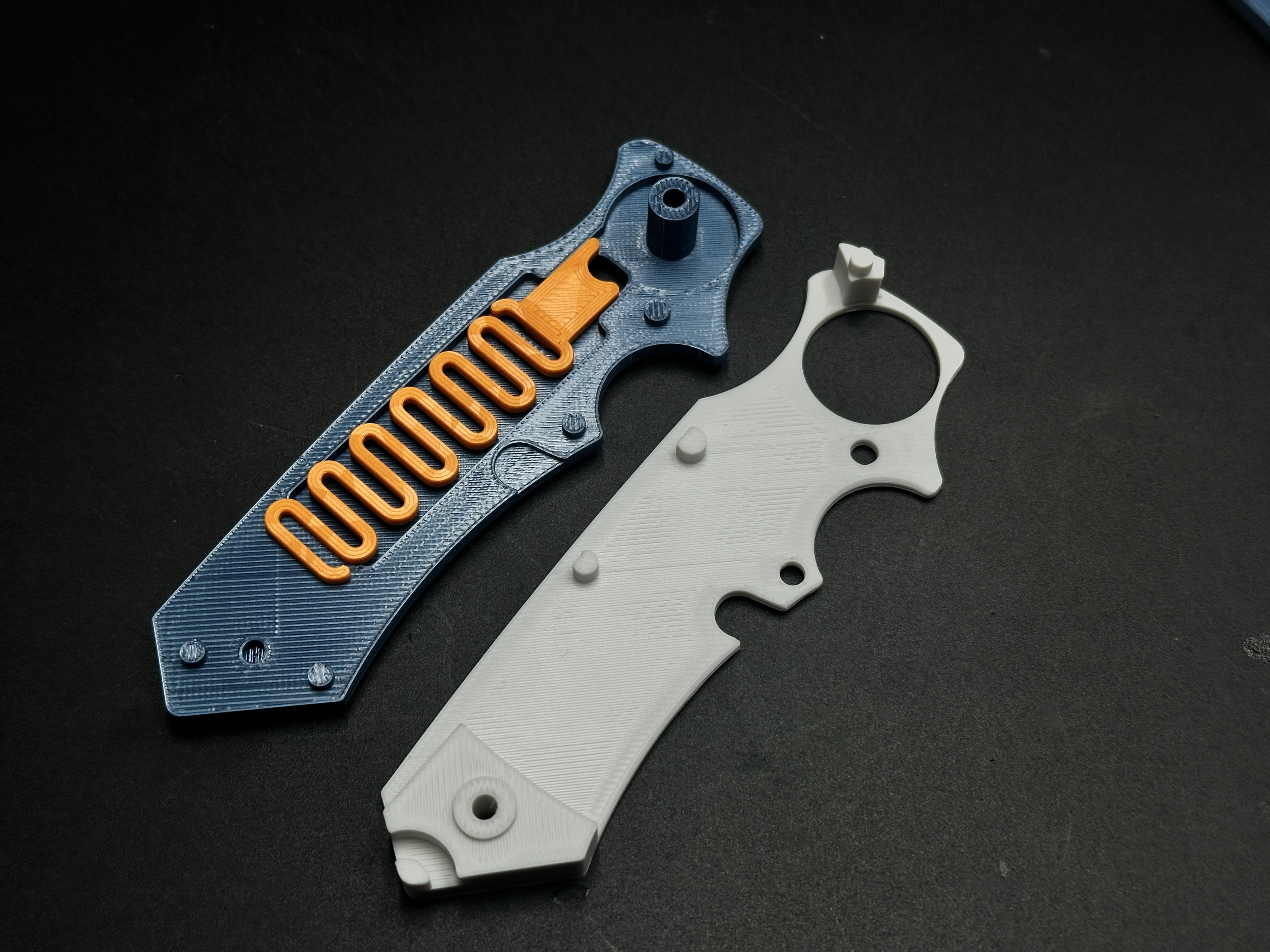
3.Left Sub-assembly: Snap the handle liner (White) over the locking spring to complete the left side.
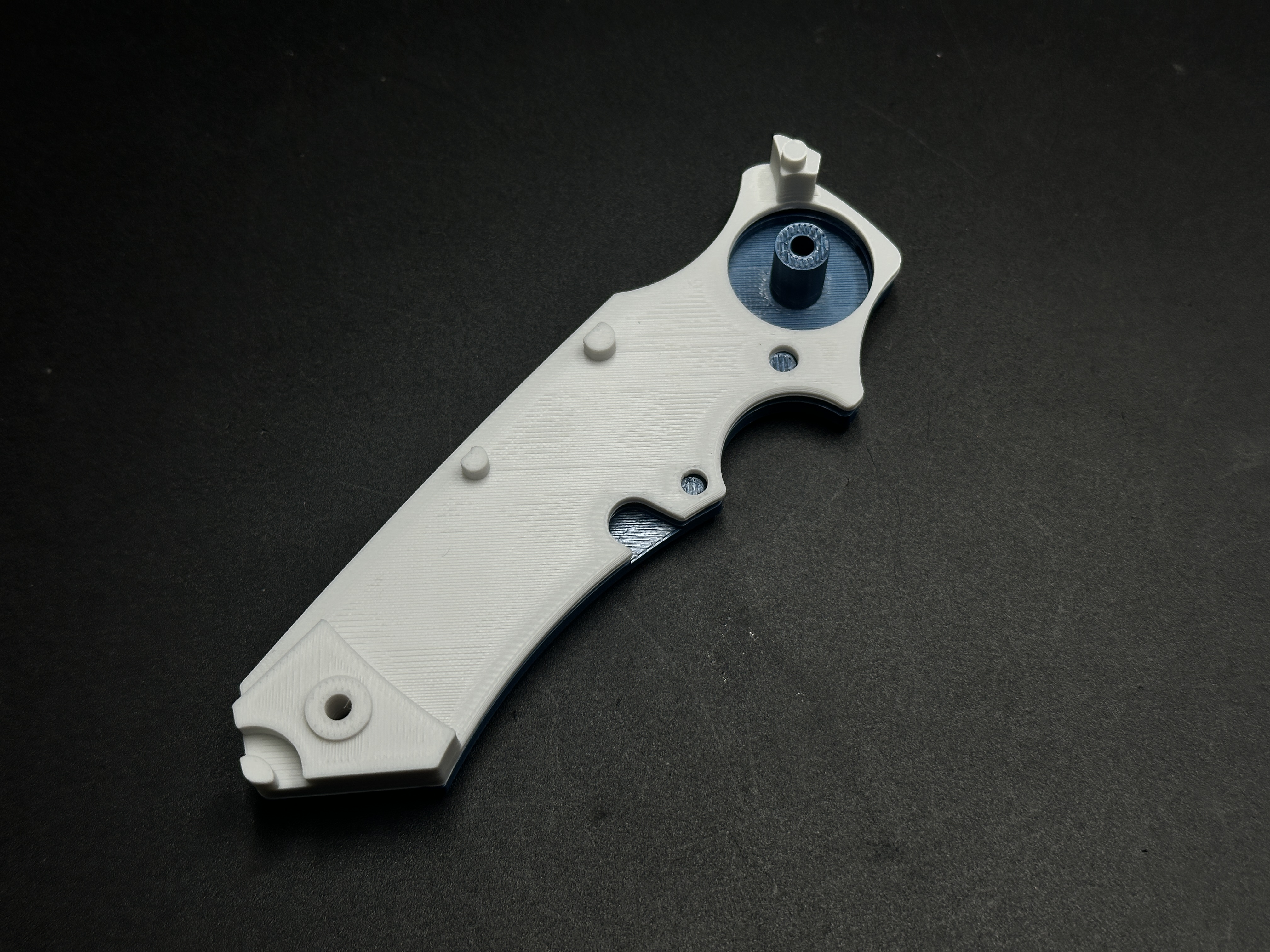
4.Pin Installation: Insert the D-shaped locking pin (Orange) into the blade holder. No glue is required; the pin will be secured by the outer housing.
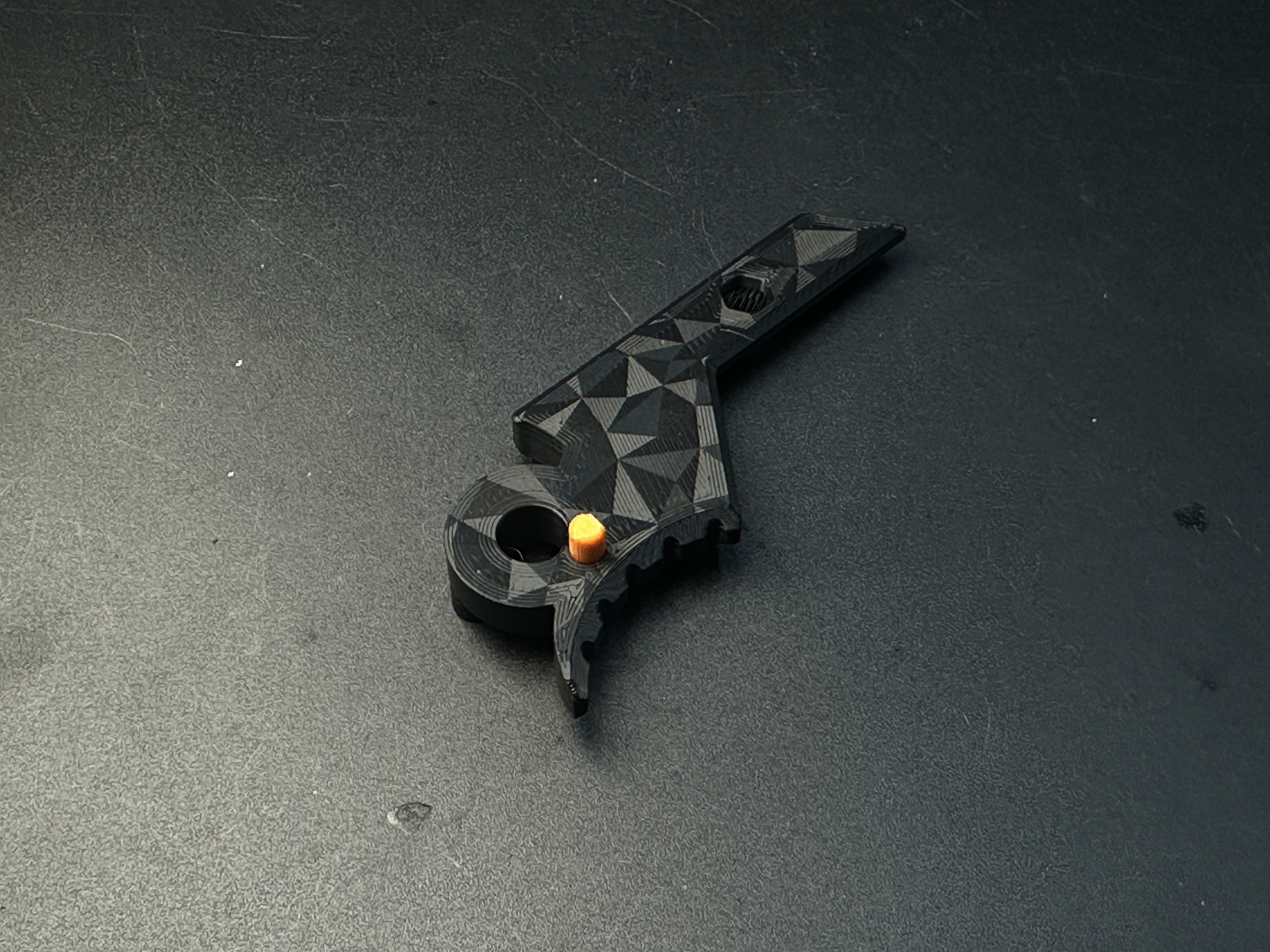
5.Core Assembly: Mount the blade holder (Black) onto the pivot of the left handle. Secure the backspacer (Black) into its corresponding slot.
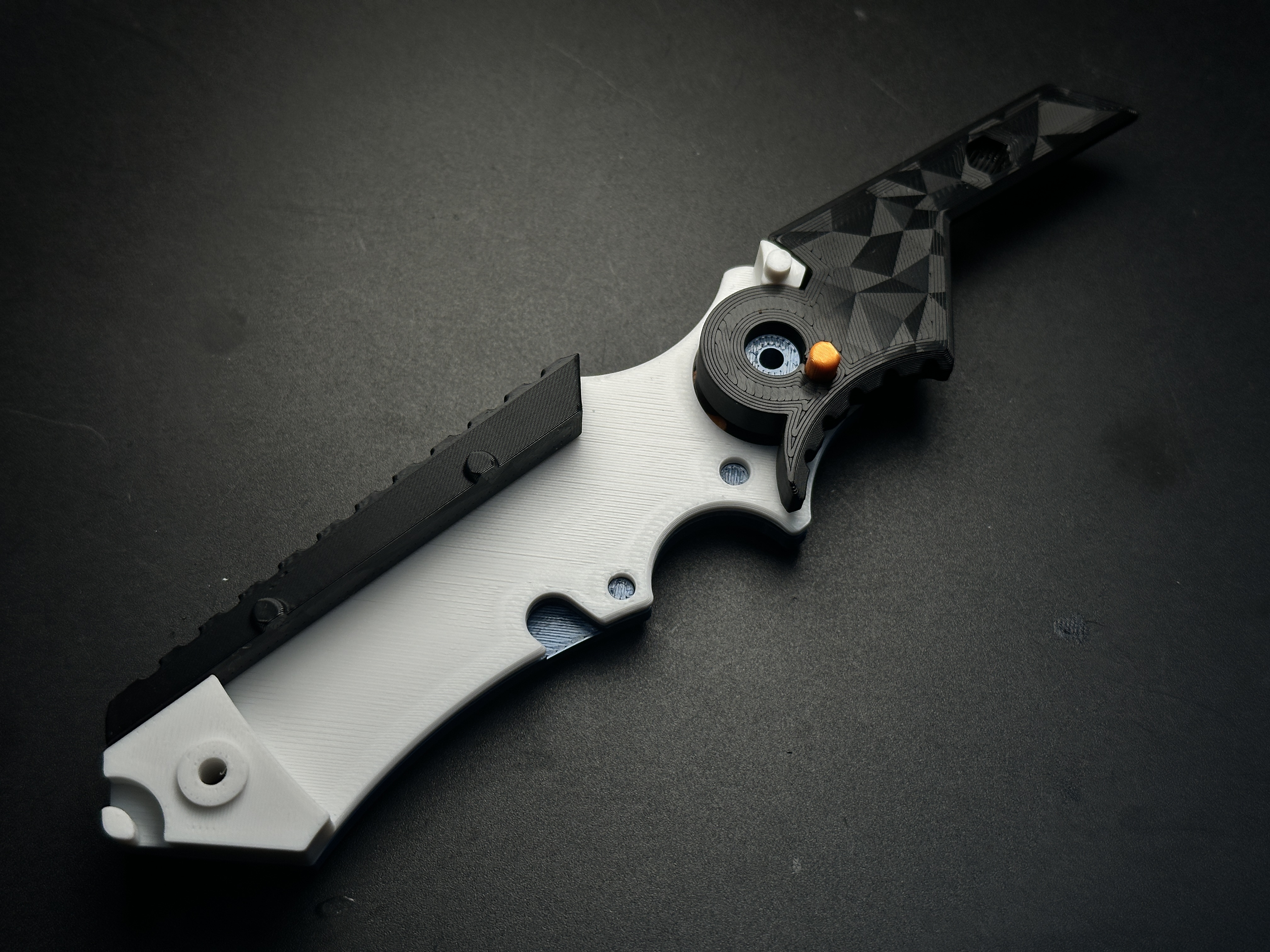
6.Assisted System: Place the right handle liner (Blue) over the assembly and install the asymmetric assisted-opening spring (Orange).
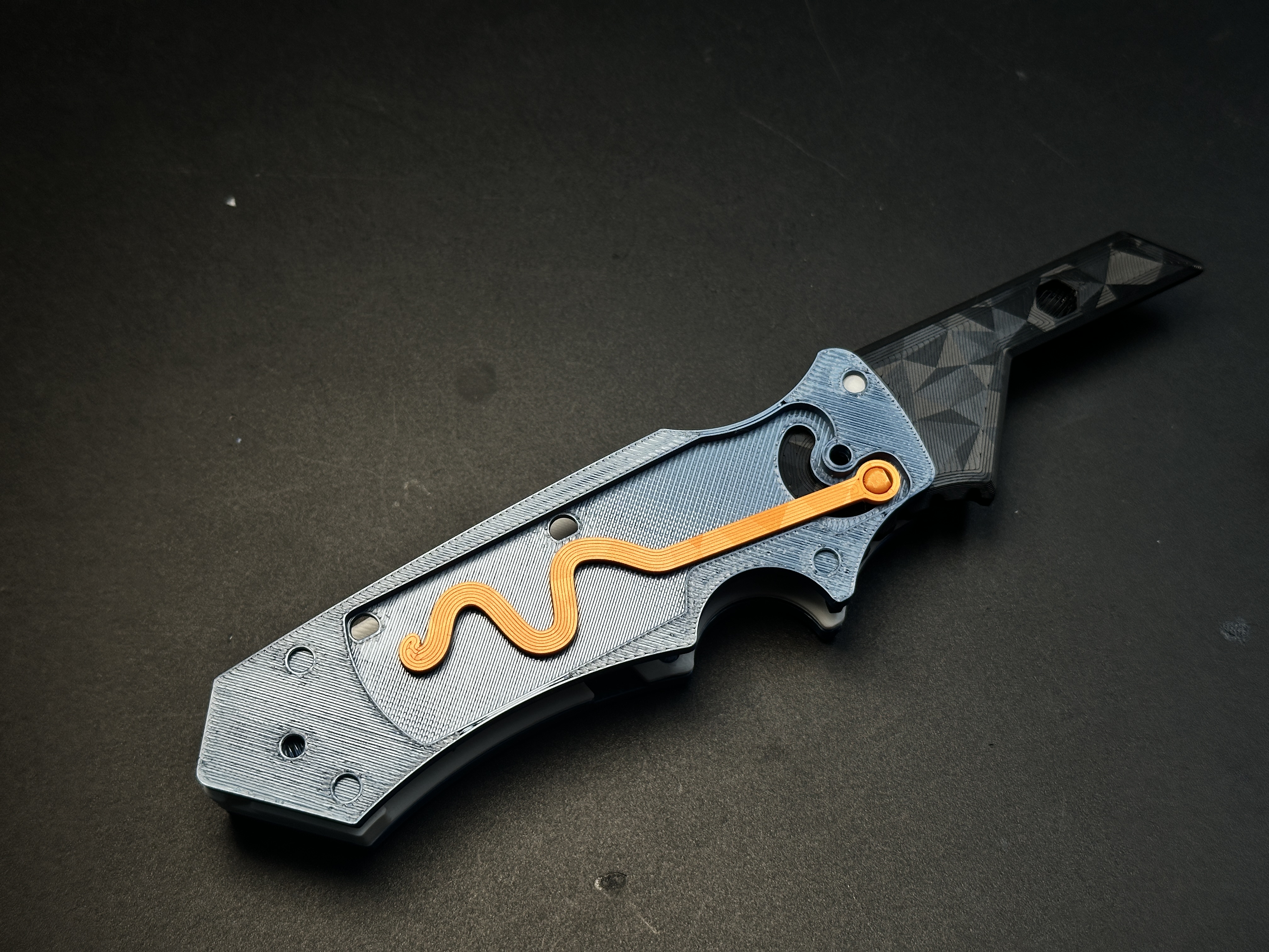
7.Right Housing: Snap the right outer handle shell (White) into position.
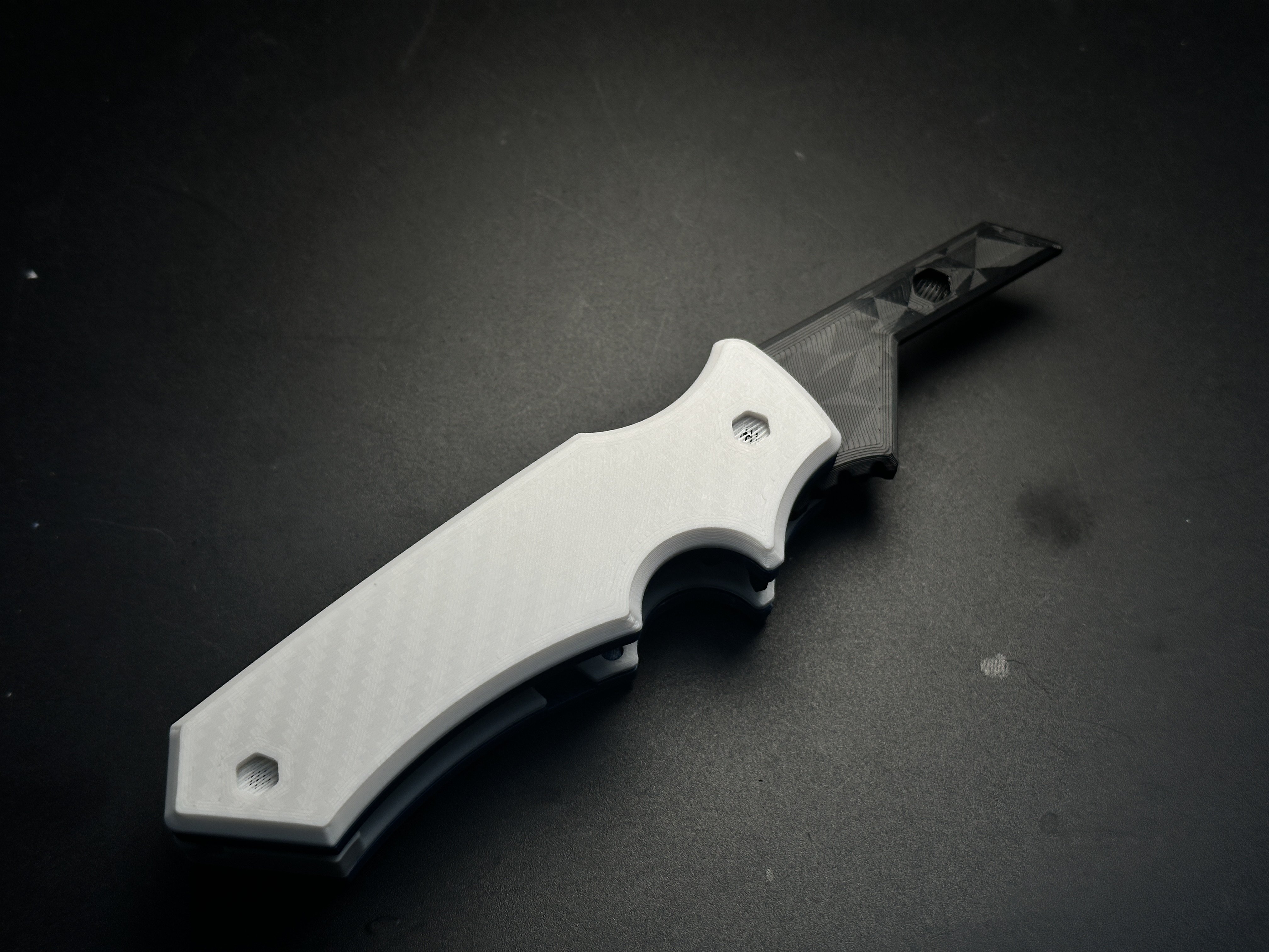
8. Final Fastening: Secure the entire handle assembly using the two M3-18mm screws and nuts. Install the blade using an M3-6mm screw and nut to finalize the build.
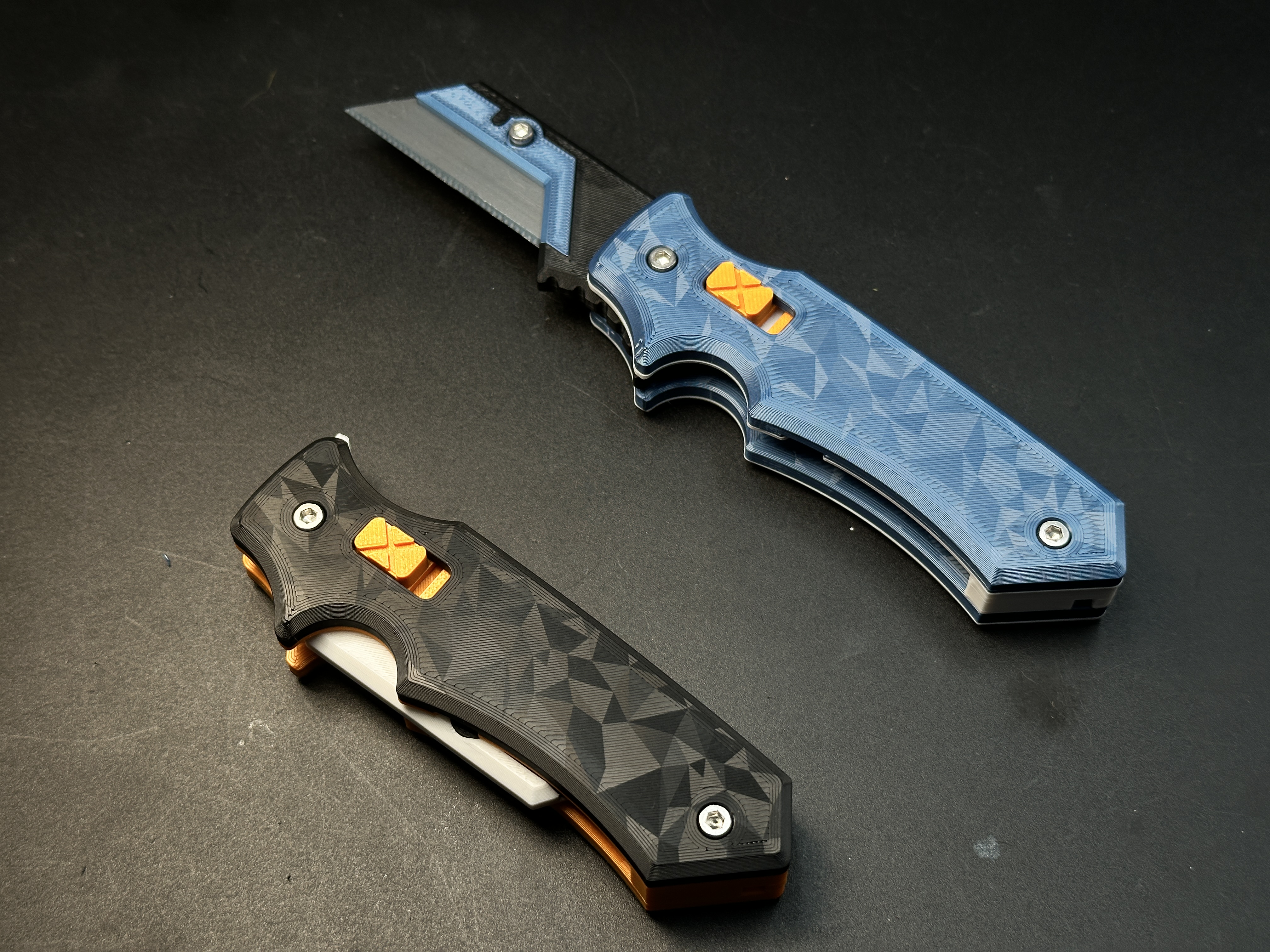
Hawk-Lock Kinetic Folder [assisted-opening system]

Publicado em 21 de fev de 2026
Gostou deste modelo? Crie uma conta grátis para salvar seus favoritos e voltar a eles depois.
Criar conta