Você está no 3DFinder
Buscamos em Thingiverse, MakerWorld e Printables ao mesmo tempo para te dar o melhor de cada uma.
Descrição
Are you tired of fully printed bearings that don't work well enough? Then this parametric ball bearing model generator is the perfect solution.
3D printing has its limitations, especially with curved parts. This is why fully 3D printed ball bearings simply can't compare to commercial ones.
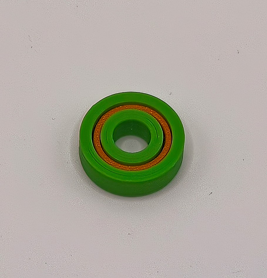
The solution is to remove the most difficult part - the balls. By using proper bearing balls and 3D printing the rest, you can get very close to the real thing.
This is a perfect solution when you can't decide which bearing size to use, or when the size you need is not readily available.
Depending on the material used, it can be a very good substitute for a commercial bearing.
If you need something that will work like a bearing should, look no further.
Read the rest of the page for more important information.
You will need to dial in the scaling based on your printer and material. If you plan on making multiple, I suggest you print one by one until you dial in the settings.
Features
- Fully parametric
- Gothic arch geometry of bearing raceways
- Assembled like a proper bearing
- The parametric model includes helpful assembly tools
Material selection
Material selection is important if you want the bearings to be useful.
In order, from most suitable to least suitable material:
- PPS-CF and PPA-CF
- Nylon (PA), -CF or -GF
- PETG-CF
- ABS/ASA -CF
- PLA-CF
You can use non-fiber-reinforced versions, but fiber reinforcements make the print more dimensionally stable during printing (less shrinking) and add extra stiffness, which is desirable in a bearing.
If you are making the bearing for test fitting only, then PLA will be your best choice. For functional parts, I recommend using at least PETG-CF, but Nylon will be a much better choice if you can print it.
The bearings will be limited by maximum speed and load, depending on the selected material.
Parameters
You can adjust the following parameters:
- id - bearing inner bore diameter in [mm].
- od - bearing outer diameter in [mm].
- h - bearing thickness in [mm].
- ball_size - steel bearing ball size in [mm] you plan to use (see below for more information).
- spacing - this parameter slightly increases the ball size to add some clearance between the bearing raceways and the balls. Most likely, the value will be between 0 and 0.05.
Decreasing it will increase friction, but improve positioning accuracy. Making this parameter too small may prevent the bearing from spinning.
Increasing it will decrease friction, but also decrease positioning accuracy.
The value depends on your printer, material flow calibration, and material shrinking. - chamfer - edge chamfer in [mm]. I recommend using a small value for easier insertion into holes.
- tools - select “Yes” or “No” if you want to generate additional tools that will help you with bearing assembly.
Ball size selection
The maximum ball size depends on bearing parameters. There should be a minimum of 3 walls with a 0.4 mm nozzle at the thinnest part of the bearing. You should confirm the generated 3D model after slicing.
Calculate the following values:
- a = ((od - id) / 2) - ball_size
- b = h - 2 - ball_size
Value “a” should be greater than 2.4 mm. Value “b” should be greater than 0.
If that is not the case, the minimum wall thickness may be too low, or the bearing balls may protrude outside the bearing.
Printing tips
- Scaling - Since materials shrink differently, you will need to scale the model appropriately. I recommend you first print one for testing. Measure it, and adjust the scale based on your measurements.
- Seam position - I set it to random. This will distribute the seams along the model, but it won't produce the smoothest surface.
You can place it in a straight line and sand and polish it out of the model. This will result in much smoother rotation, but requires additional post-processing. - Layer height - Use a low layer height of 0.16 mm or less with a 0.4 mm nozzle. Use a modifier for a low layer height in the bearing raceway area, which is the critical part.
- Speed - Go slow, use a high-quality print profile, and decrease outer wall speeds.
- Wall loops - Use a minimum of 3 wall loops. Ideally, print the bearing solid. Increase the number of wall loops instead of setting 100% infill.
In addition to proper scaling, a very important thing is to keep your print bed clean. You will be printing some tiny parts with a small surface area. Print bed adhesion issues are a user issue, not a print profile/model issue.
You can enable brim. It will need to be properly removed, which requires additional post-processing time.
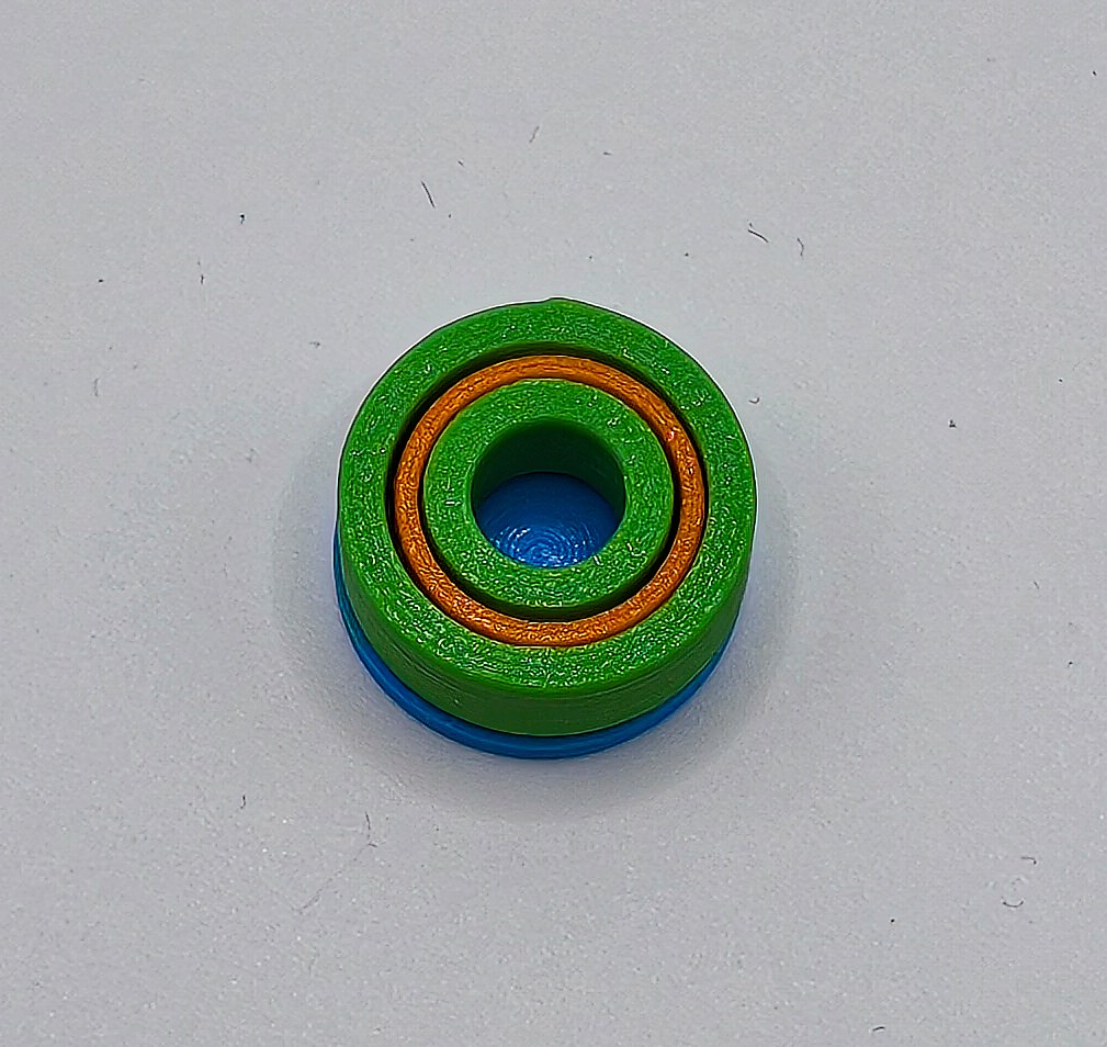
Assembly
The assembly procedure is similar to commercial bearing assembly procedures.
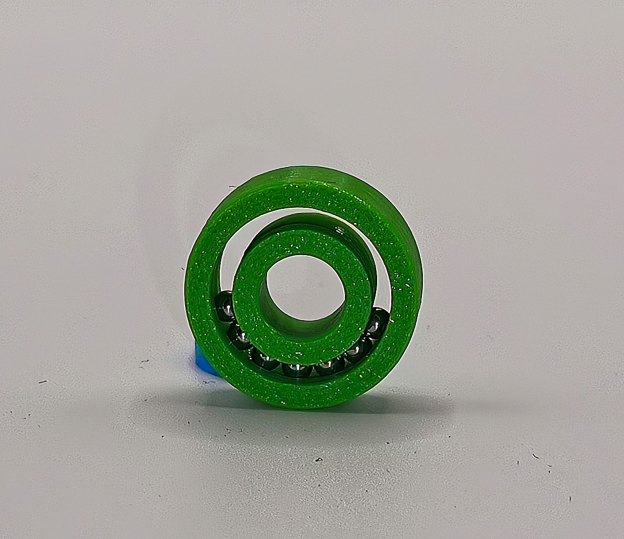
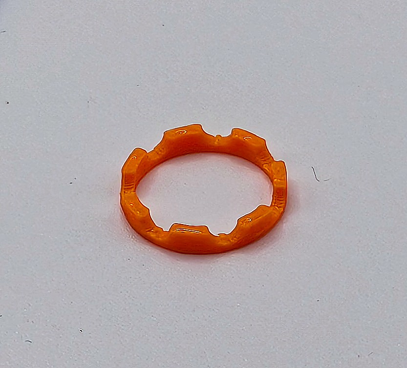
Prepare the required number of bearing balls. You can get the number by counting the slots in the bearing ball cage half part. For example, my custom 608 bearing uses 7 x 3 mm balls.
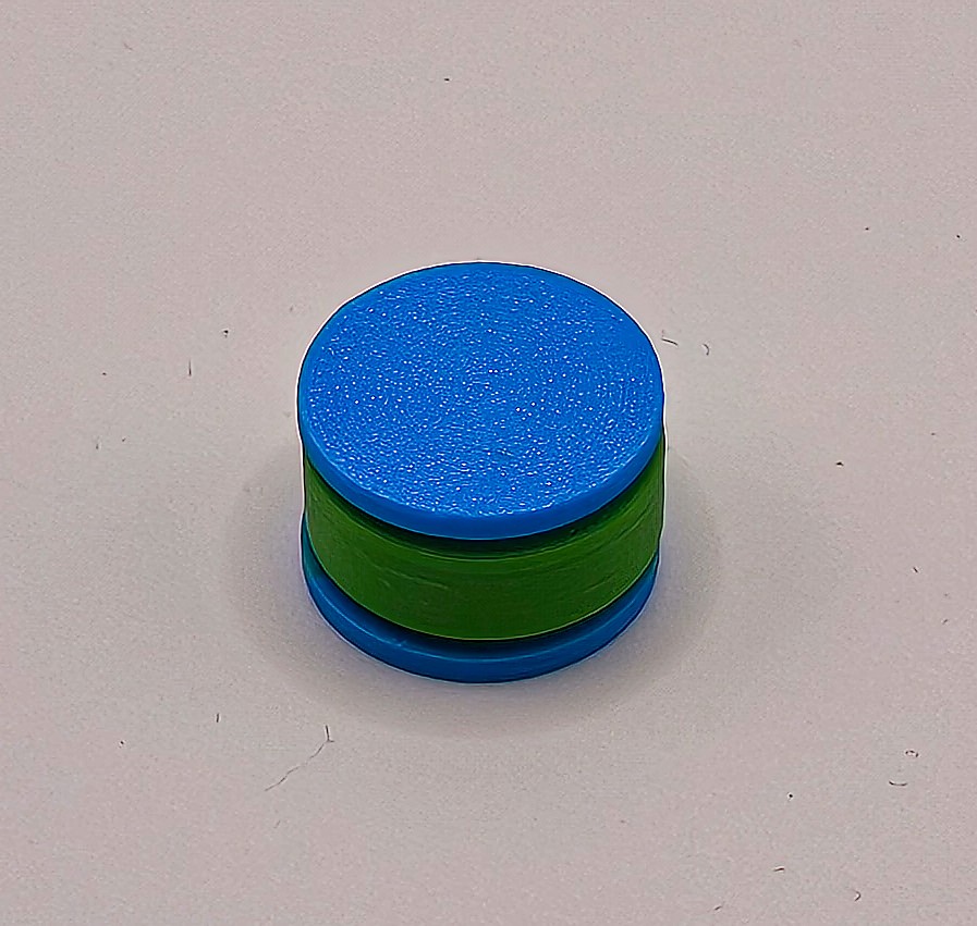
Assembly can be a bit difficult the first few times, but I can make a 608 bearing, shown below, in less than a minute now.
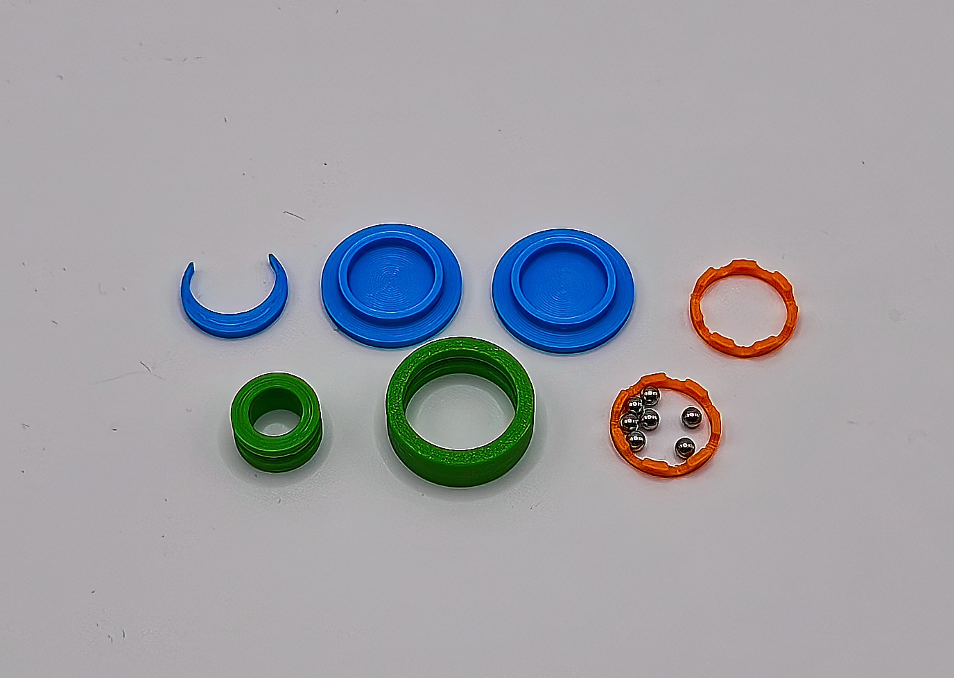
Step 1
Insert the crescent-shaped part between the inner and outer bearing parts. This will keep the balls in the correct position.
Add a bit of grease to the exposed raceway to keep the balls in place. Grease will also keep the bearing functional for longer.
Start adding the balls into the opening.
Using round-tipped tweezers will make assembly easier.
Another way is to do it without the insert part. Stand the bearing on its side and add the balls in the greased raceway. Carefully insert the inside part.
If the spacing parameter is too high, the balls won't stay in place, as there will be too much space. If you are having difficulties, try decreasing the spacing value.
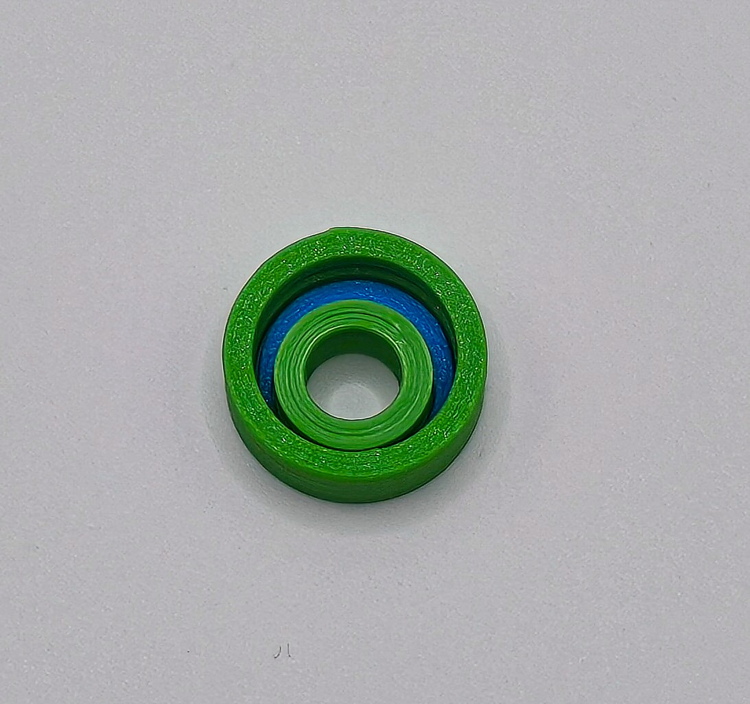
Step 2
Once you have added the required number of balls, press the inner bearing part against the balls.
Carefully remove the insert part while keeping pressure on the balls. If you do it correctly, the balls will stay in place.
Slide a few of the balls to the other end. This will lock the inner part and prevent the balls from falling out.
If you didn't use grease in the previous step, I recommend adding it to each bearing ball now. Do not overdo it.
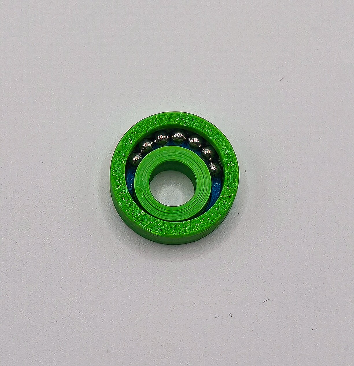
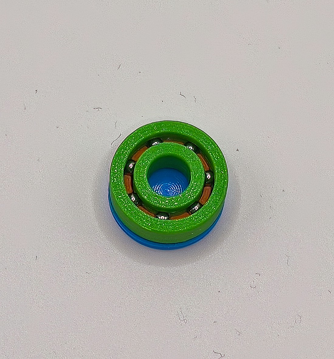
Step 3
Space the balls evenly around the bearing.
Insert one half of the cage and top it with the circular tool part. Rotate the assembly.
Add a small amount of glue to the other cage part. Insert it carefully so you don't accidentally glue the balls. Top it with the other circular tool part. The glue type will depend on the material used.
Press firmly until the glue cures.
I rotate the assembly a few times during curing to make sure I didn't accidentally glue the balls in place.
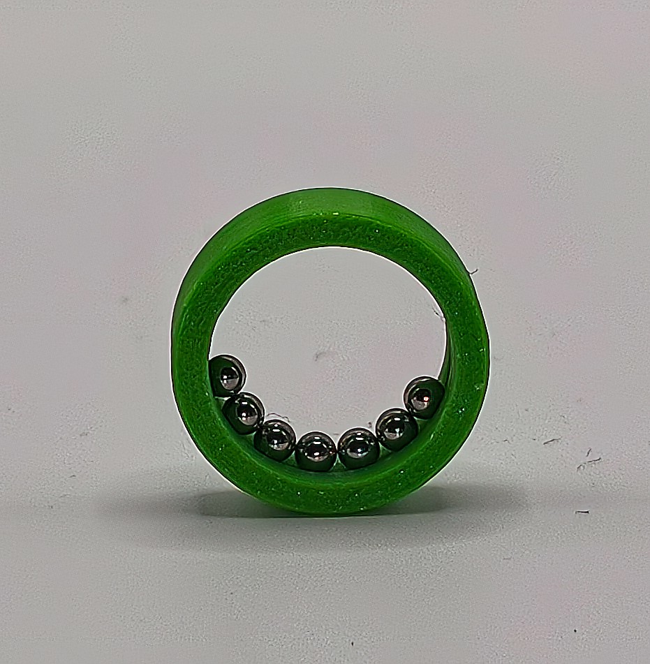
Step 4
Break in the bearing. If you sanded the seams, this step may not even be required.
Rotate the outer and inner parts alternately, while keeping the other one fixed. After a while, the movement should get smoother.
Check the rotation of the cage. If it is spinning at the same speed as the inner/outer part, then the balls are not properly rotating, but rubbing. This will decrease the bearing lifespan. There is nothing you can do at this stage. For the next bearings, you can try sanding and polishing the seams. It may also improve over time with use.
Parametric Ball Bearing Generator

Publicado em 16 de fev de 2026