Você está no 3DFinder
Buscamos em Thingiverse, MakerWorld e Printables ao mesmo tempo para te dar o melhor de cada uma.
Descrição
4/25/26 Update
- ⚠️ Important before you go further this model includes the V1 hole component and the V2 hole component. These hole sections are different dimensions so make sure you are using the correct model for your application. The 3 filler pieces are the same and attach to the V1 and V2.
- Print the component with the hole using 4 wall loops and 25% gyroid infill. This provides sufficient material for the heat set inserts to bond securely while minimizing the risk of deformation.
- The remaining components may be printed with 8–10% infill and 3 wall loops; however, 2 wall loops may be sufficient if the infill percentage is increased slightly.
- The model orientation has been corrected in Fusion 360, so files downloaded from the model generator should already be properly aligned to the build plate for printing. Refer to the guide below to verify proper orientation before printing.
- Incorrect orientation may result in print failures or excessively tight dovetails. Only the component with the hole requires supports.
- Dovetail clearance gap is now adjustable. This number will always be a negative number. Current setting is -.055mm and I would not adjust any larger than .080 or the parts will be sloppy when they slide together. This adjustment is only on parts with a female dovetail and is not adjustable on the male side. There is also a little more clearance in the corners of the dovetail to aid parts sliding easily. Recommended that you test print both sections of the dovetail to verify tolerance before printing the whole project.
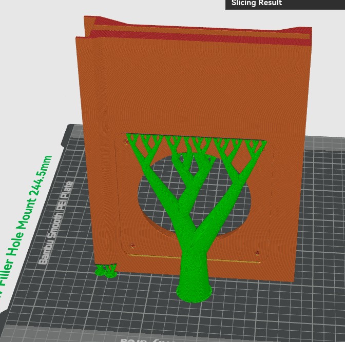
The hole filler component is orientated on the bottom face with the dovetail up top. This can be printed like the other pieces below but will generate more supports if not done like I have suggested.
 s
s
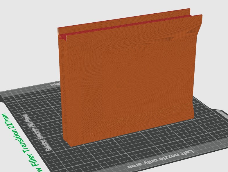
All other components are orientated like below. Dovetails should be on the sides. Use the auto rotate feature in Bambu Studio and it will automatically put the part in the correct orientation. (Differing orientations in any other way will potentially cause a print failure or the parts may not fit together correctly. NO supports should be generated printing these other parts so orientation absolutely matters.) Feel free to message me if you have any questions and I should respond back within 24hrs.
This is a parametric version of my window filler, allowing you to generate a custom-sized part without modifying the original 3MF or STEP files. You can now change the following parameters.
- Window channel width is adjustable from min 20mm to max 60mm. The section that fits over the sliding window is automatically generated to be 1mm wider than the selected value to ensure proper fitment.
- The overall height of the part is also customizable.
⚠️ Important: The transition filler and hole adapter parts should not be generated less than 150mm and will cause the generator to fail to include the entire hole or transition if less than this value. - Maximum height is limited by your printer’s build volume.
📏 Tip: When setting the height, add your window channel height to the total height of this part. Example: If your height value is 230mm and the channel height is 10mm, then your overall height of the part will be 240mm. Top and Hole pieces are both set up this way. - The window channel height is fully customizable to match your specific window channel. See the pictures below for reference examples.
Both V1 and V2 versions are included:
- 🔹 V1 – Designed primarily for 3" systems using a 120mm Noctua fan, ideal for exhausting fumes.
- 🔹 V2 – Designed for 4" systems, typically used with laser engravers and external exhaust fans.
- 🔹 Window Top, Window Filler, and Window Transition parts are compatible with V1 and V2.
✅ Adjustable width
✅ Adjustable height
⚠️ Minimum height limits apply
🖨️ Limited by printer build height
Measure window channel width of window. This is the value you will need to put into the model generator. The part that fits the window will automatically generate 1mm wider than this value.
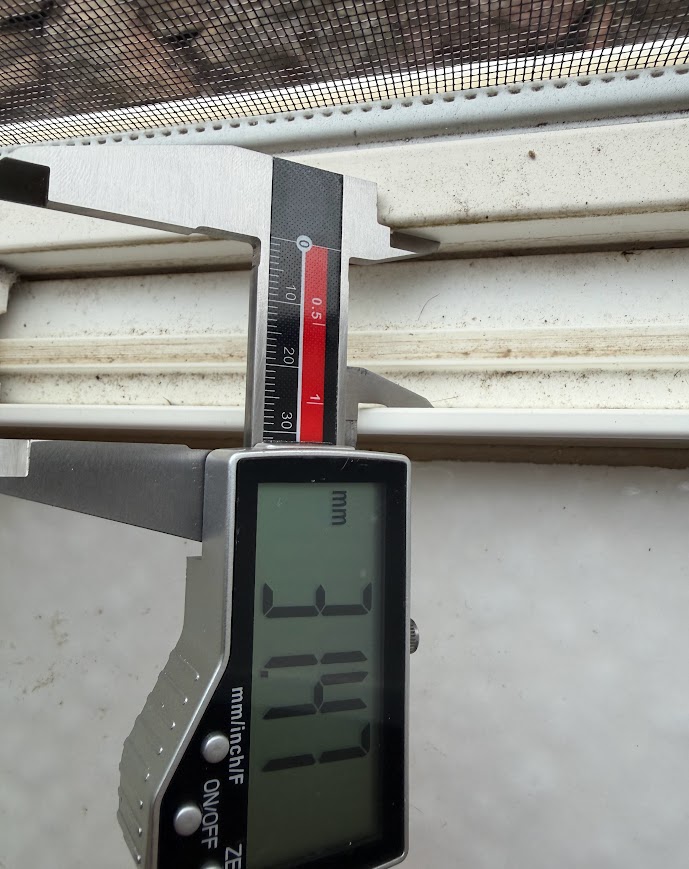
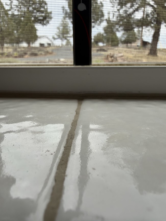
Measure the window channel height from the highest point inside the window channel to the top of the channel lip. In some windows, there may be a raised strip or track that sits higher than the rest of the channel. If this is the case, measure from the top of that raised strip to the top edge of the channel lip.
In my example, the small strip running down the channel is higher than the rest of the channel, so that is the point the measurement was taken from.
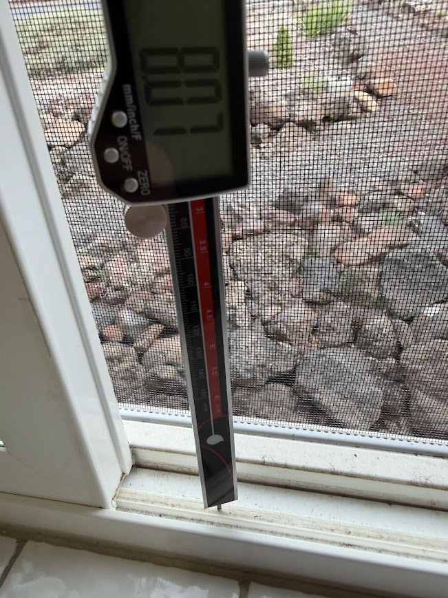
Your measuring device should about flush with the top lip of the channel. This measurement will be added to the window filler top and the window filler with the hole in it at the bottom. The other parts of the window filler don't need this extension.
To ensure your measurements are correct, it is recommended to cut the parts into smaller sections in your slicer and print test pieces first to verify proper fitment before printing the full-size parts. See the examples below where another user printed small test sections for fitment.
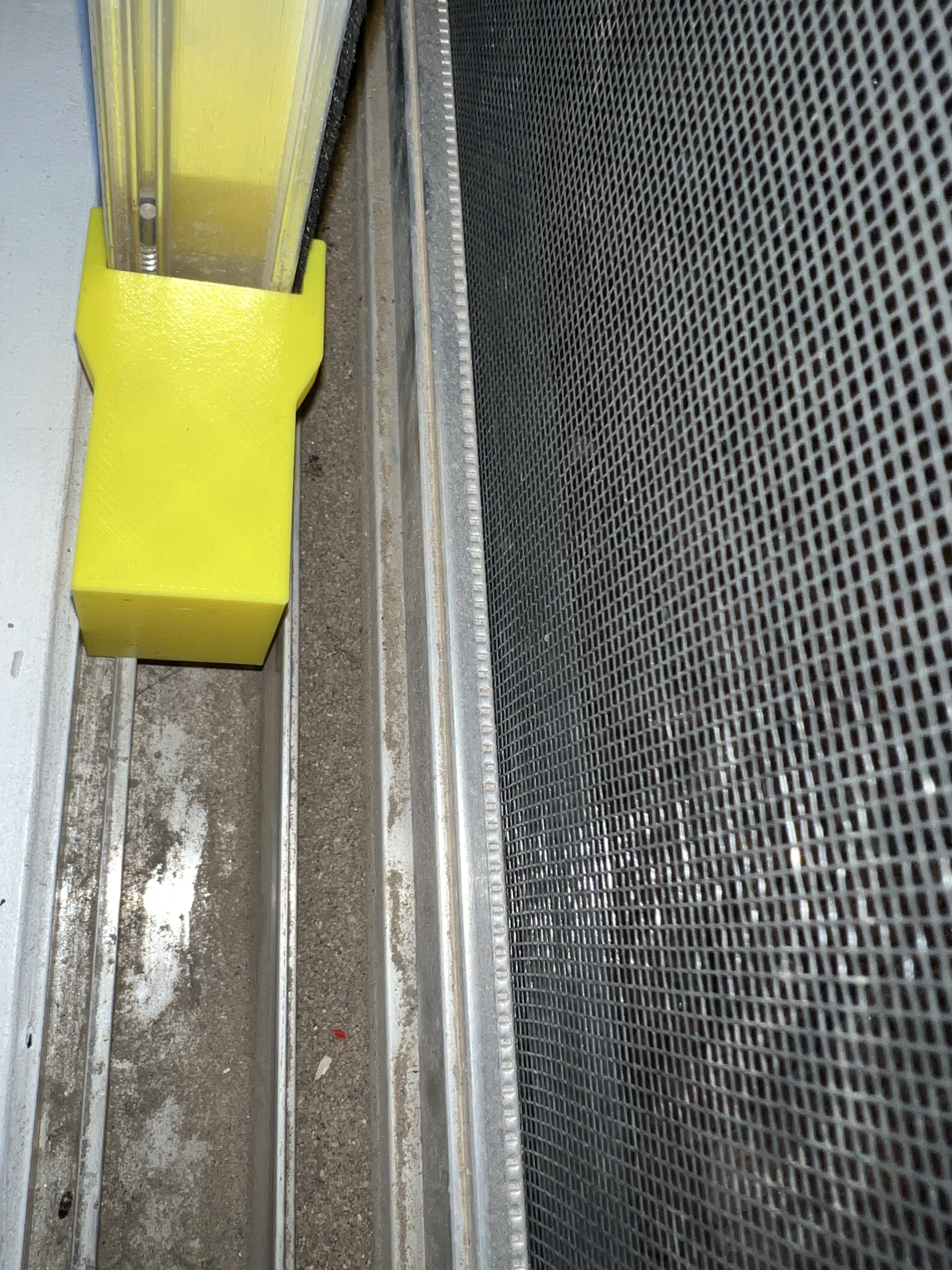
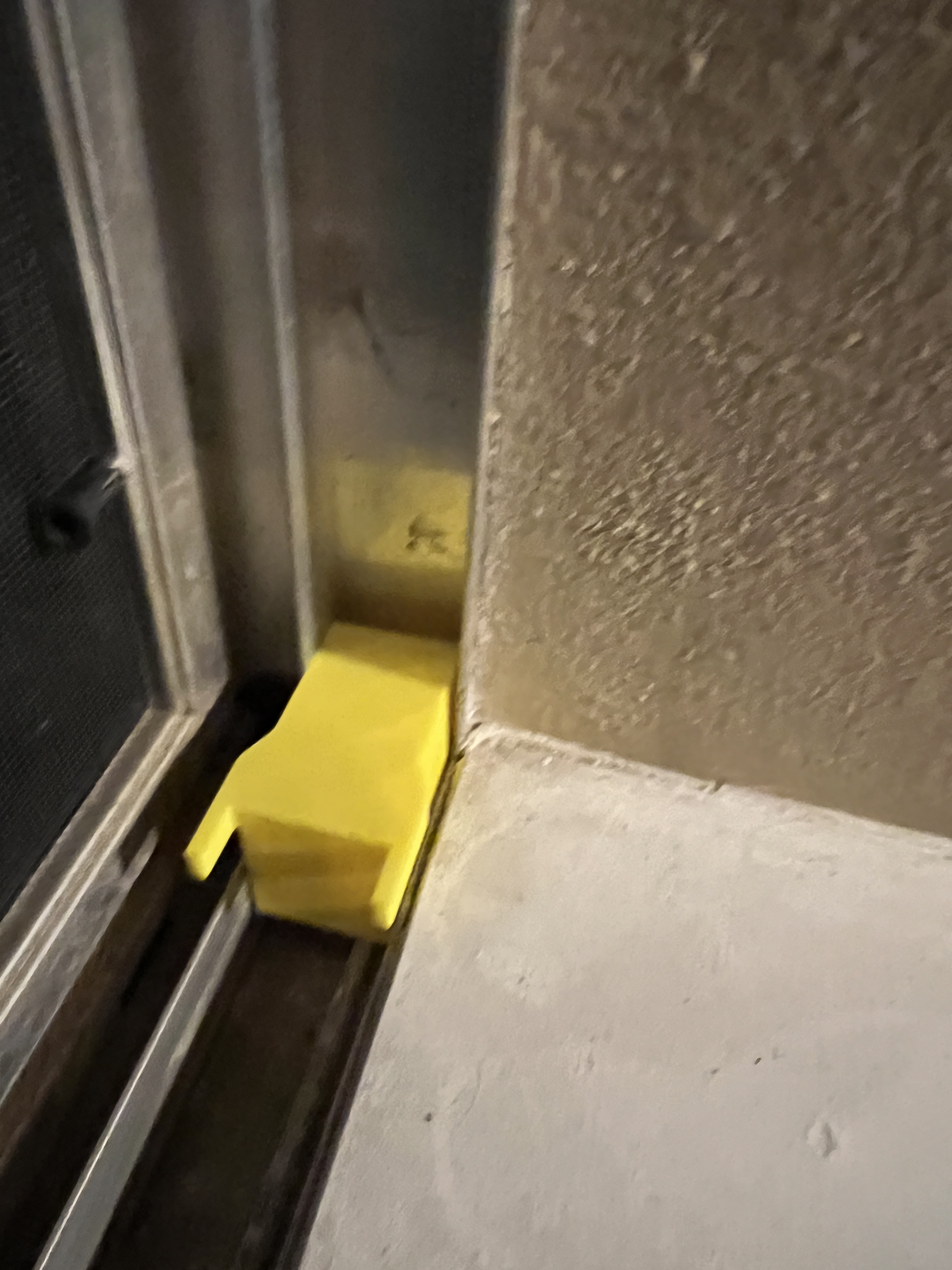
The part should fit around the sliding window frame while also fitting inside the window channel. Be sure to test fit on the opposite side of the window frame as well to confirm clearances.
The ears that extend around the window frame should sit slightly above the top lip of the window frame so the window can fully close and seat properly.
You can find the complete exhaust system model here:
Old System V1 works with 3D Printers (Exhaust System)
V2 System works with 3D Printers and Laser Engravers that require higher volume (Exhaust System V2)