This model is designed for installing the Chamber Exhaust Fan Kit on the P2S printer. With this kit installed, the device will add an active exhaust function, providing a solution for users with strict exhaust requirements.
The kit consists of three main components:
Chamber Exhaust Fan Housing (Mandatory to print)
Exhaust Air Duct Connector (Optional)
Air Outlet Adapter (Required to print if using the original rear panel)
Printing Tip: As some small parts will be printed, it is recommernded to apply glue to the heated bed before printing.
Upgrade Kit: The External Exhaust Fan Kit - P2S will be available for purchase starting late January, exclusively via the official Bambu Lab store. Filament Recommendation: Bambu PETG Basic series or high-temperature filaments such as ABS are recommended.
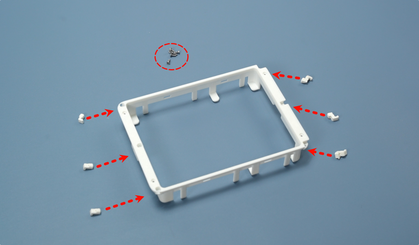
Assemble the top cover of the chamber exhaust fan: Use BT2*5 screws to fix six claws on the top cover. Before starting, place the corresponding claws next to their respective slots to avoid installation errors.
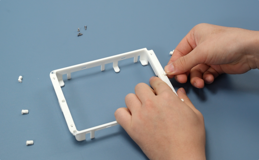
First install the three claws on the right side one by one, ensuring the claws fit with the slots.
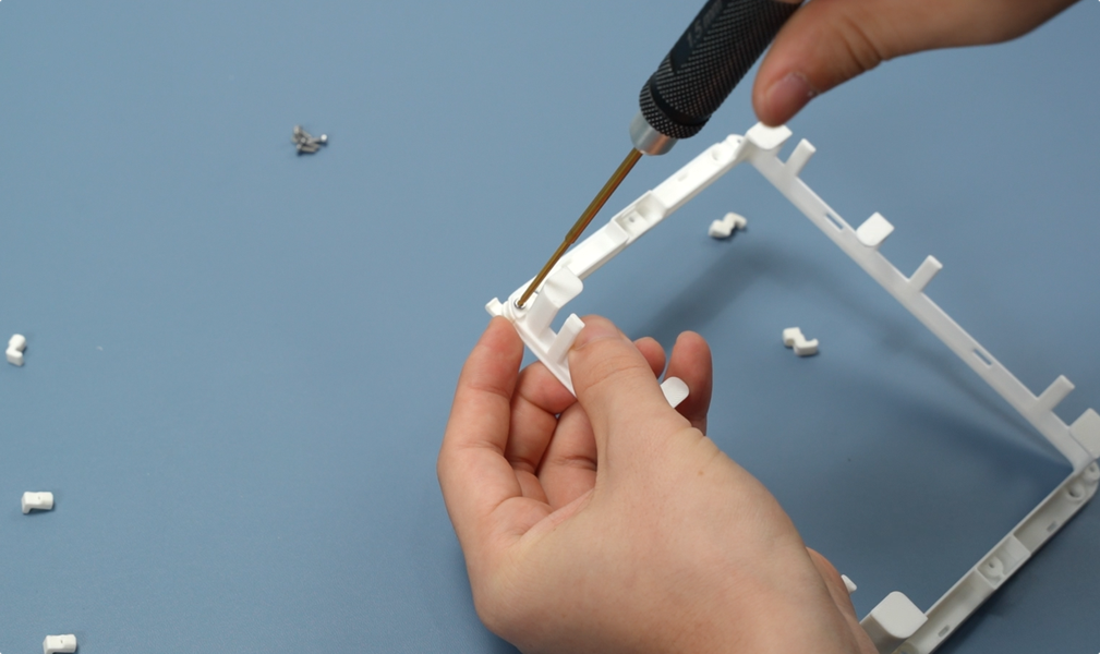
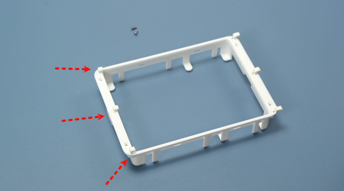
When installing the three claws on the left side, first snap all three into the slots on the left side of the top cover simultaneously, then tighten them uniformly with BT2x5 screws.
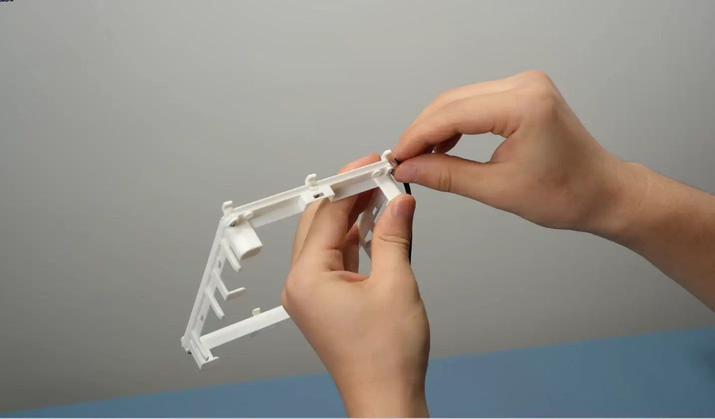
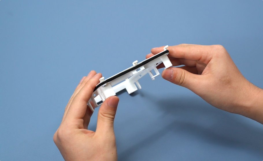
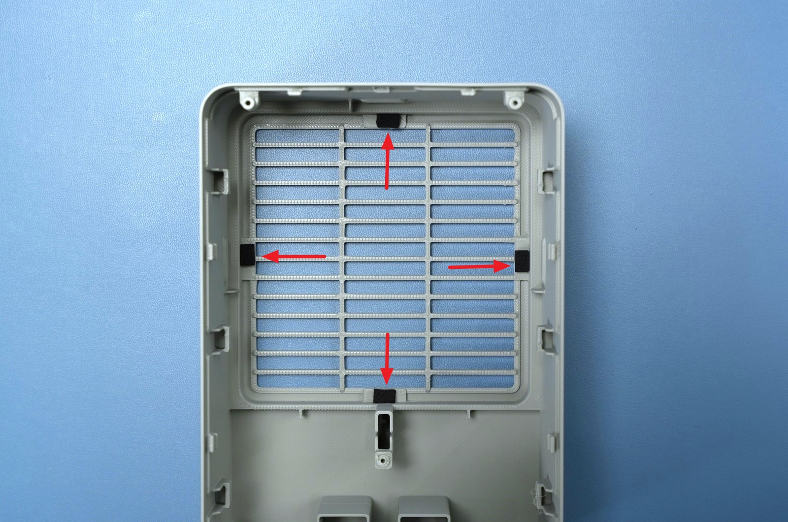
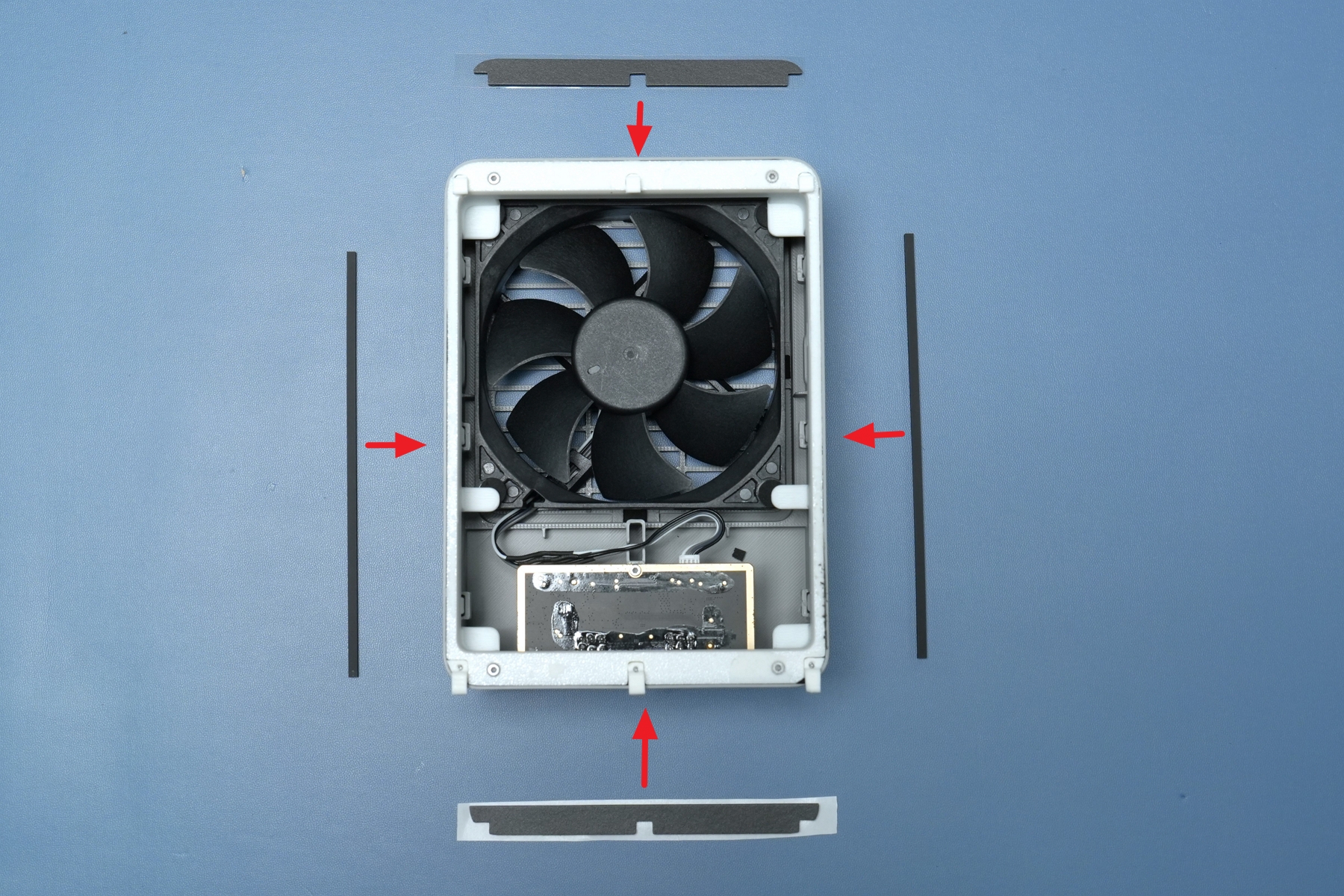
Next, perform the foam pasting operation on the chamber exhaust fan cover: First take the thin foam and paste it along three sides of the fan cover in sequence, ensuring the foam fits tightly with the cover edge.
Take the shorter section of foam and paste it on the remaining side of the cover to complete the initial foam pasting of the fan cover.
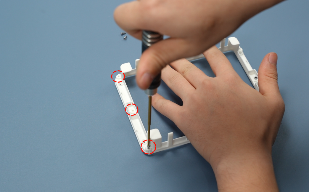
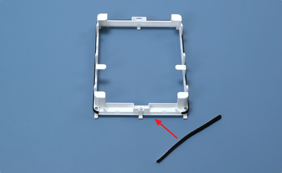
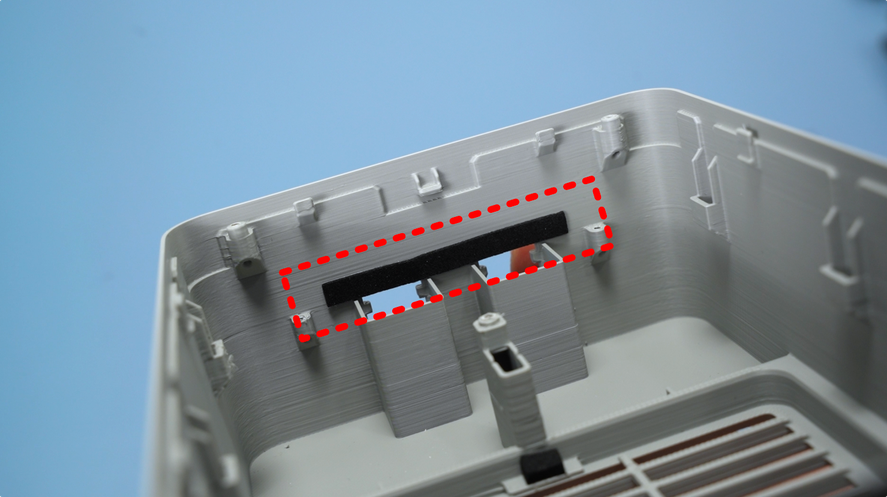
Next, paste four small foam pieces at the air outlet to reduce fan noise. Meanwhile, paste a long strip of foam above the 6pin cable connector (red-marked position in the diagram) to improve the sealing performance of the chamber exhaust fan.
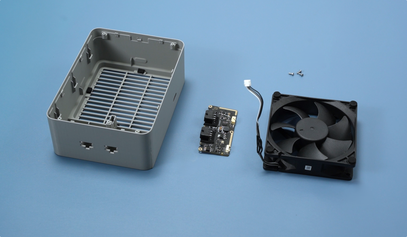
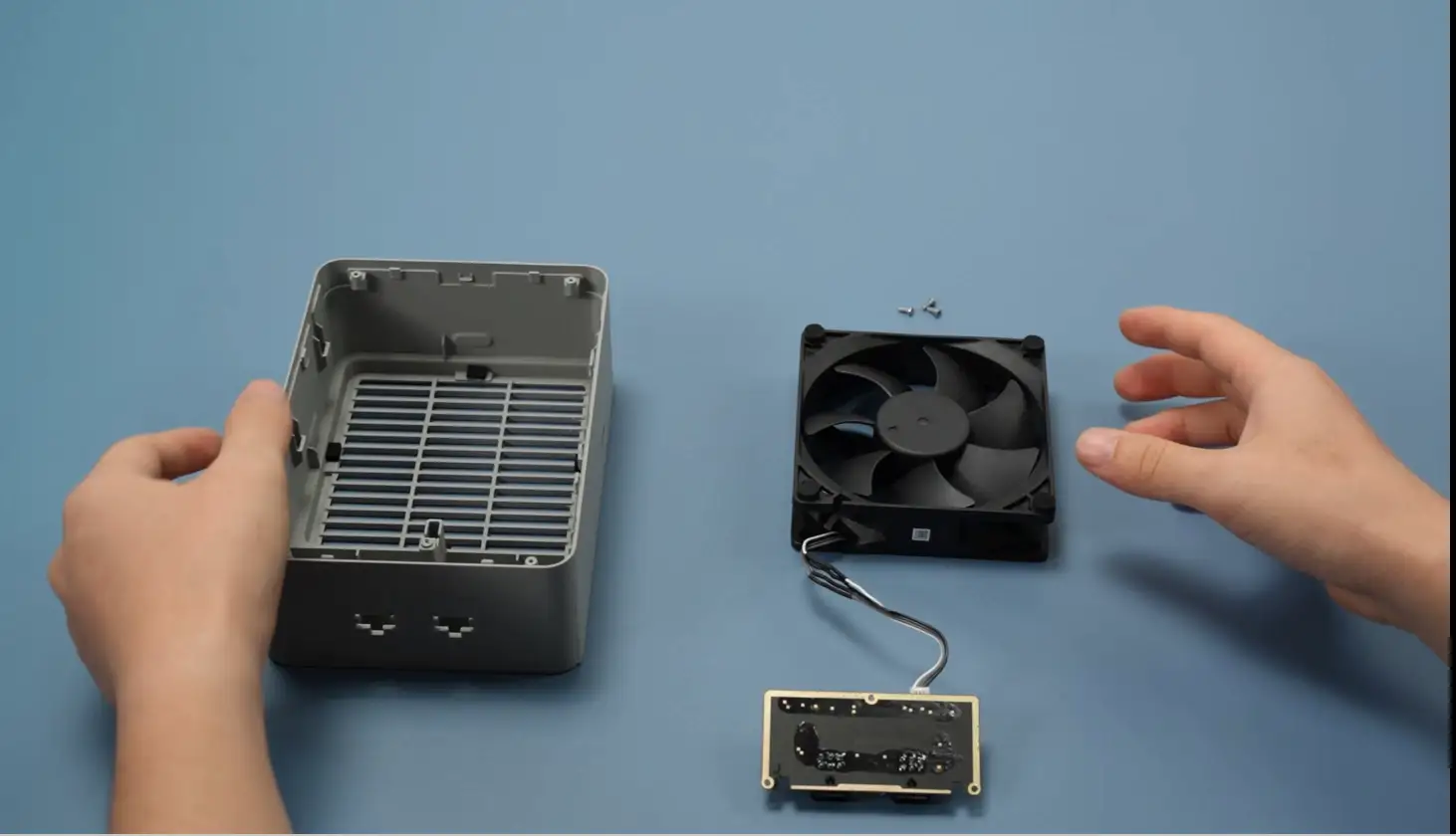
Prepare the fan housing, control board, fan, and three fixing screws.
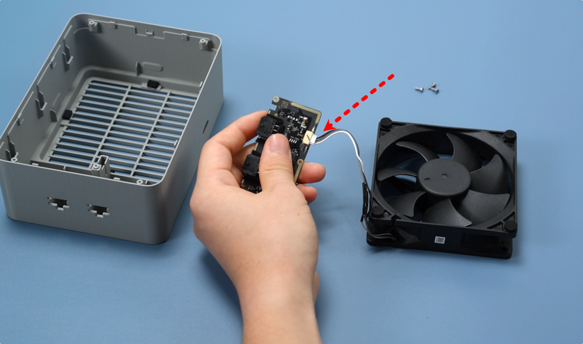
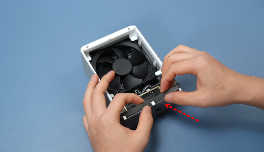
Before installing the fan and control board into the housing, first connect the fan cable to the control board, ensuring the connection is secure without looseness.
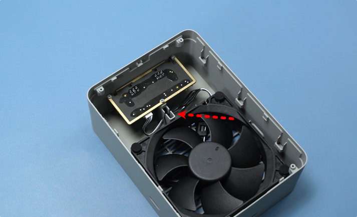
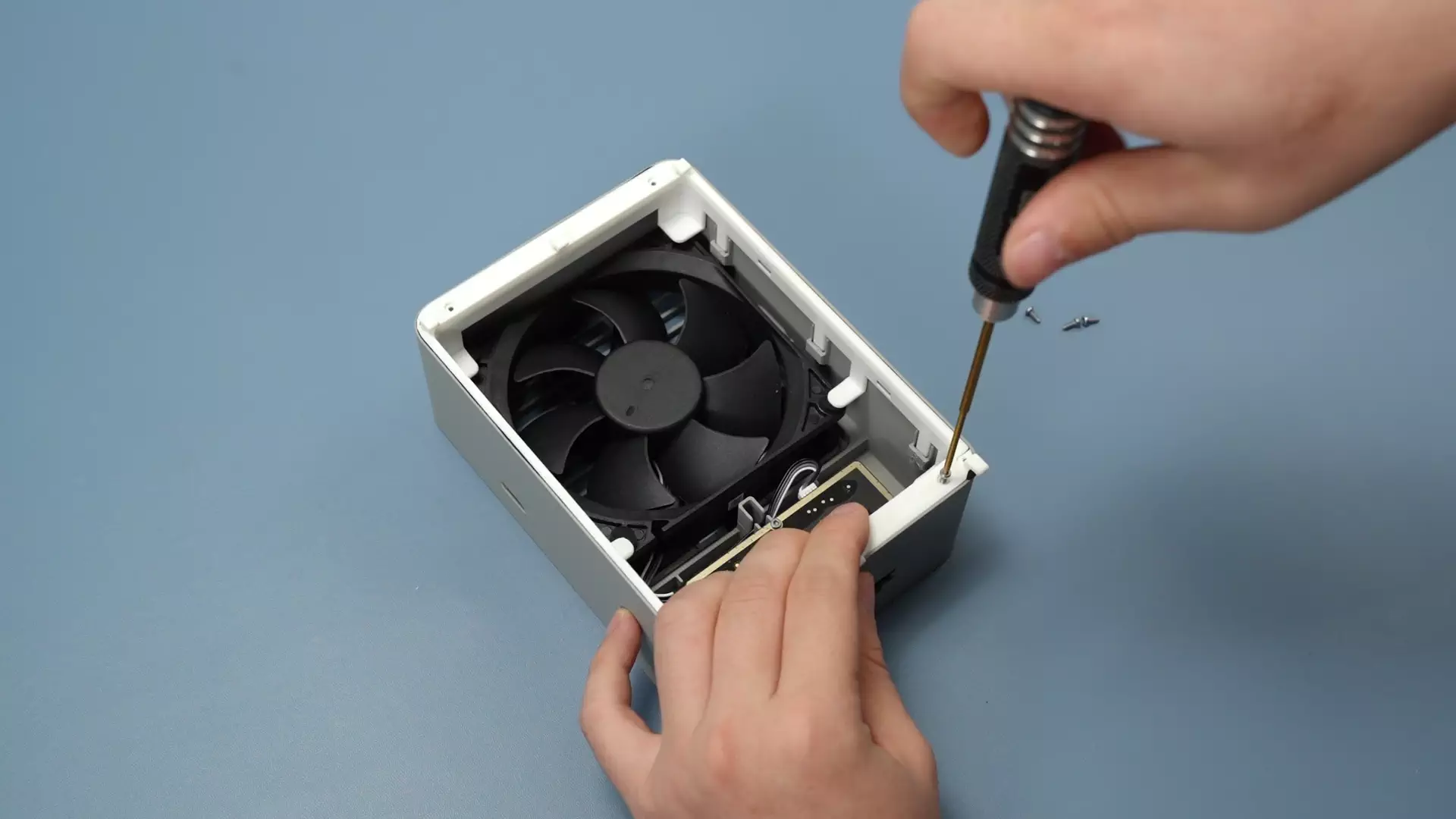
After the cable connection is completed, install the fan and control board together into the fan housing, then fix the interface board to the housing with three BT2x5 screws. After assembly, secure the excess cable into the wire slot of the housing.
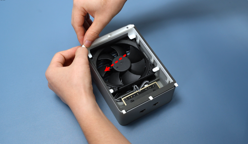
Note: The fan has a specific installation orientation requirement—install the side without the label facing inward and the side with the label facing the outside of the printer. Do not reverse the installation.
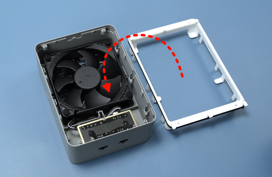
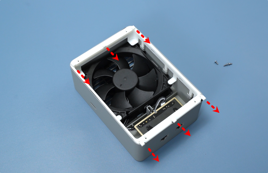
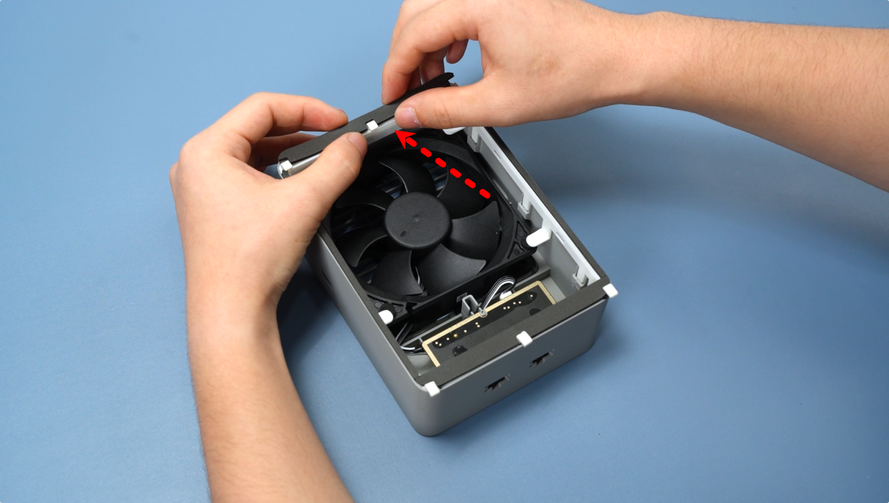
Snap the assembled top cover onto the fan housing. Pay attention to the orientation during installation—align the side with the claws facing outward with the side where the 6pin cable connector is located.
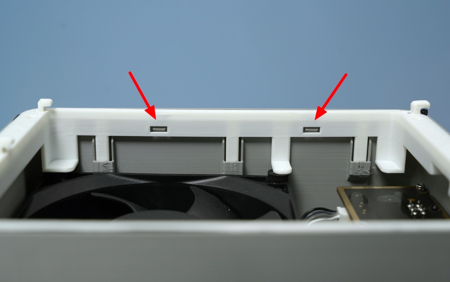
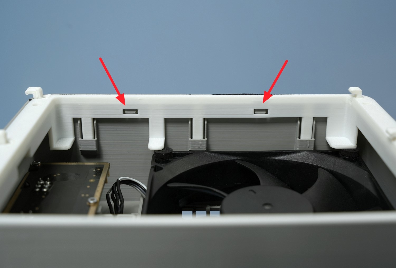
After installing the top cover, check the four buckles on the left and right sides of the fan. If all buckles are firmly engaged, the top cover is installed correctly.
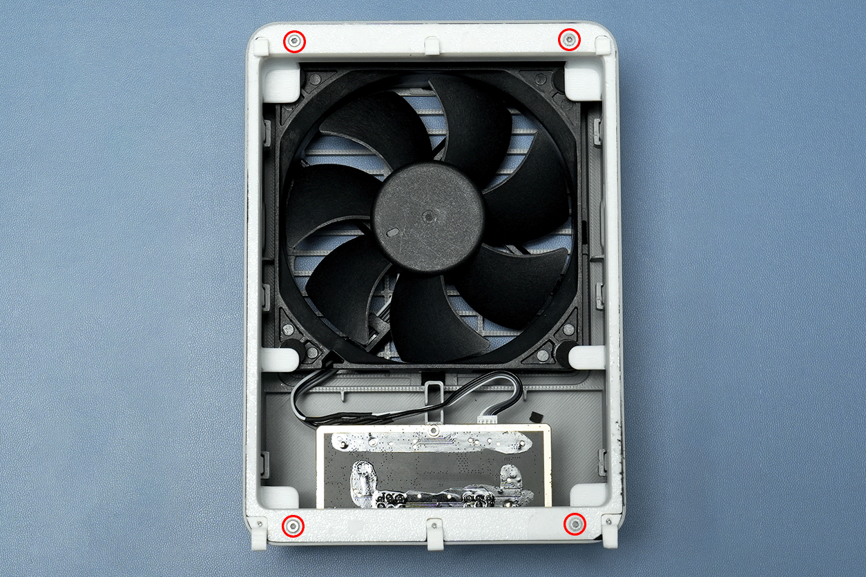
Use an H1.5 screwdriver to tighten the four fixing screws on the back of the chamber exhaust fan sequentially.
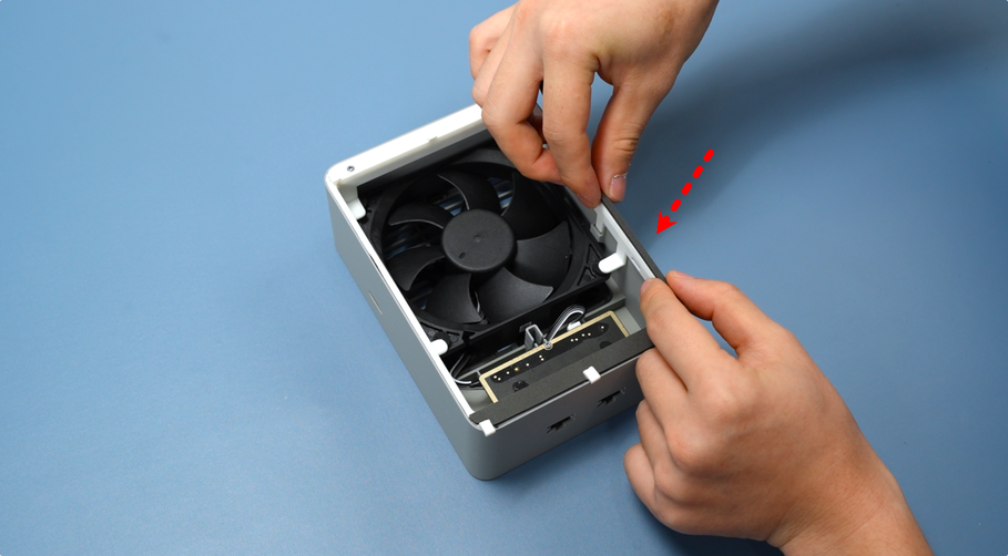
Finally, paste a circle of foam on the top of the fan. Confirm the correct position before pasting to avoid errors;
During pasting, ensure the foam is aligned with the edge, and paste the four strips of top foam one by one as shown in the diagram.
2.Install to the Printer
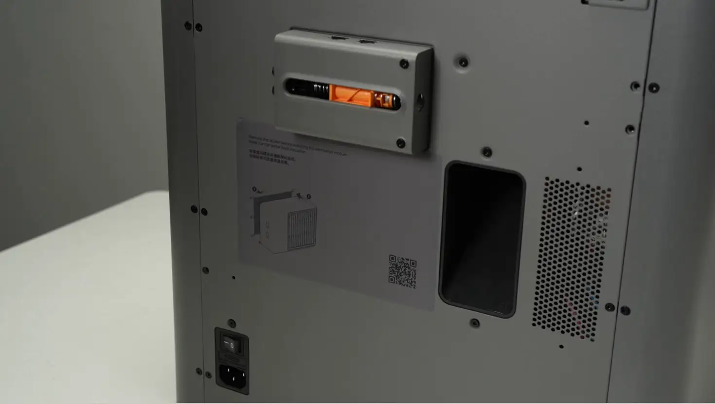
Plan 1: Use Dedicated Printer Rear Panel
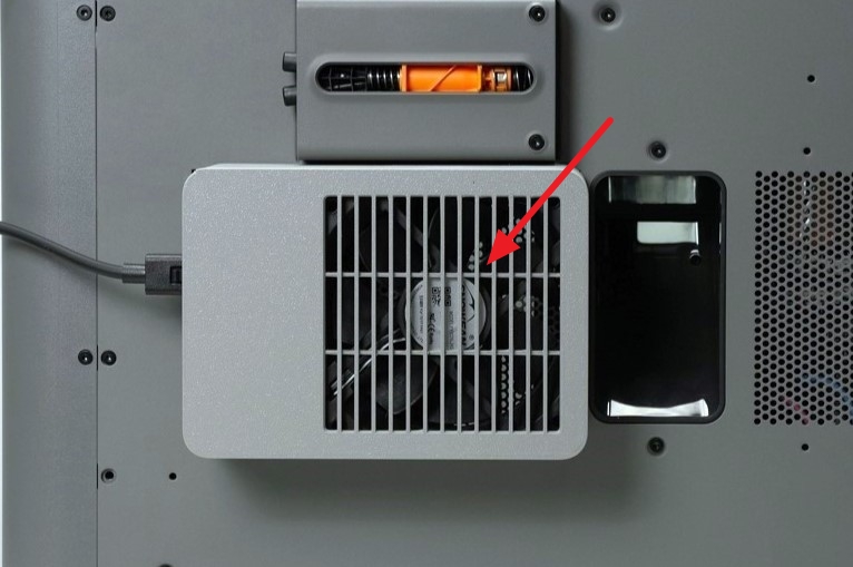
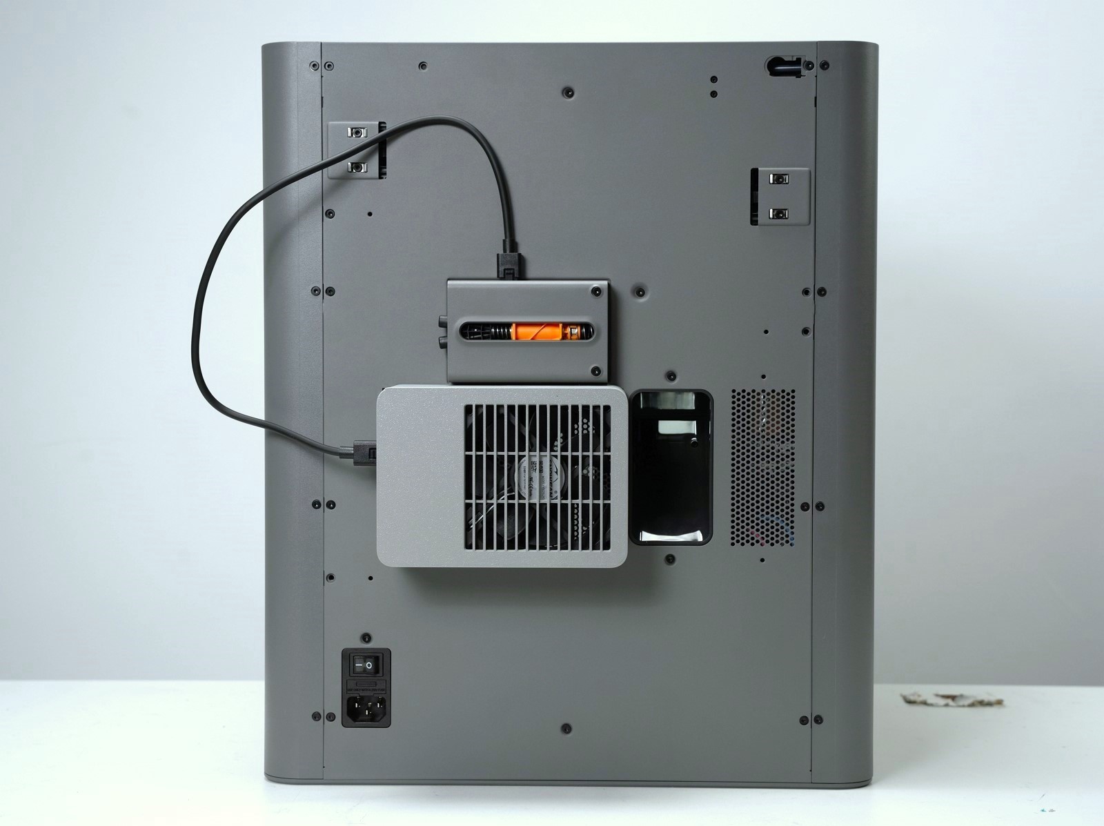
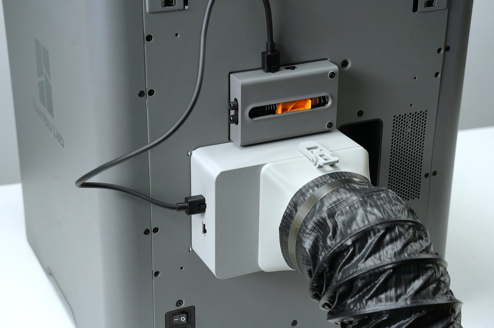
Tear off the sticker on the exhaust port of the dedicated printer rear panel to expose the installation position.
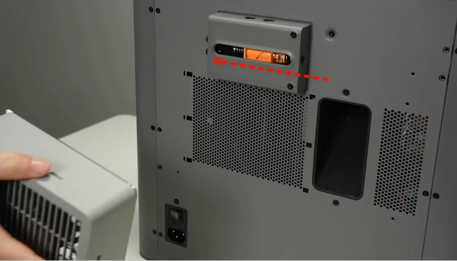
Hold the chamber exhaust fan, align it with the buckles on the rear panel, and push it to the left to directly snap the fan into the preset installation position of the rear panel. After installation, connect the 6PIN cable of the fan to the corresponding connector of the buffer.
3.Connect External Exhaust Pipe (Optional)
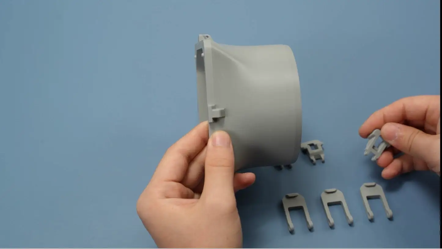
If you need to install an external exhaust pipe for the printer, first print the two accessories: pipe connector and buckle.
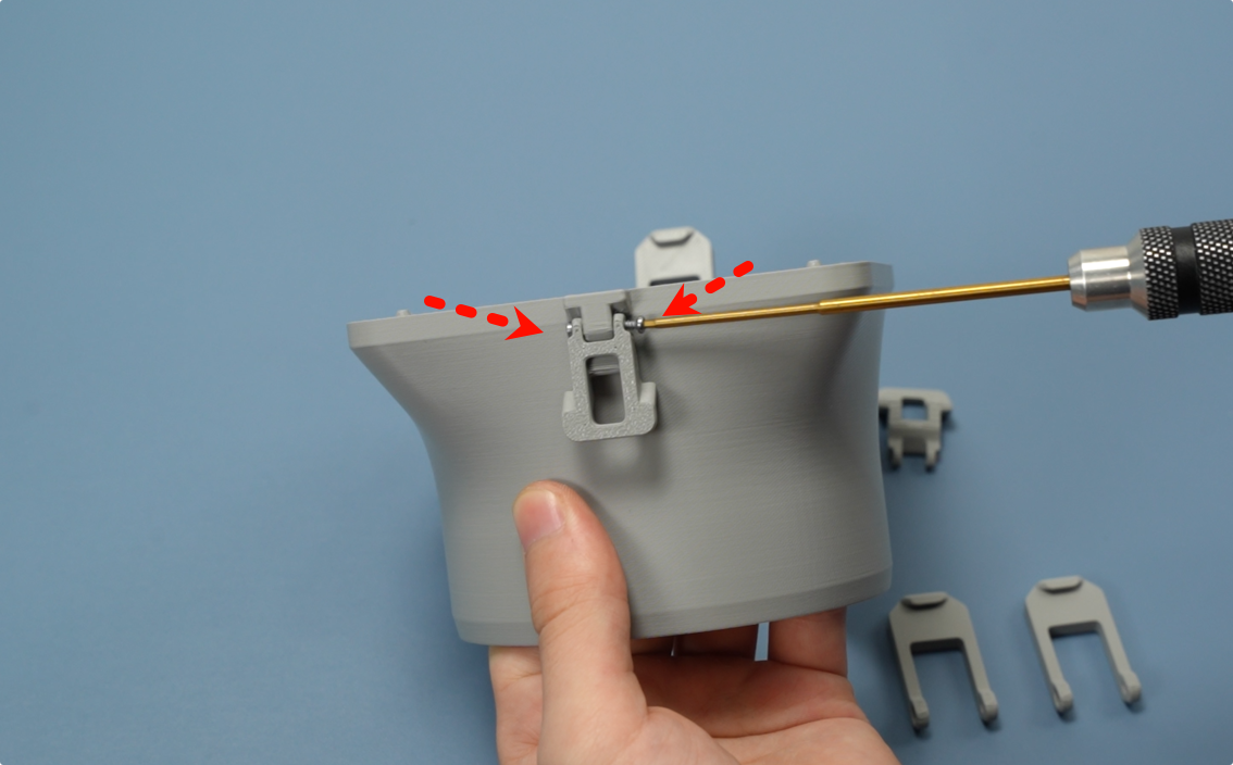
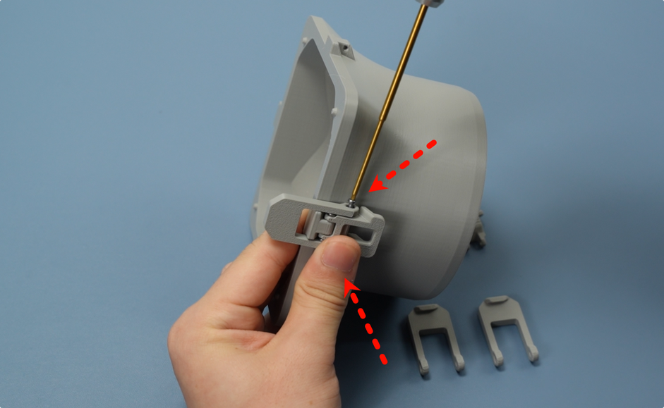
Start assembling the buckle of the exhaust pipe connector. The buckle consists of two parts: long and short. First install the shorter part on the exhaust pipe connector, then tighten the screws on the left and right sides of the part to fix it.
Note: The screws here function as shafts. Do not over-tighten during installation, otherwise the buckle will not move smoothly, affecting subsequent use.
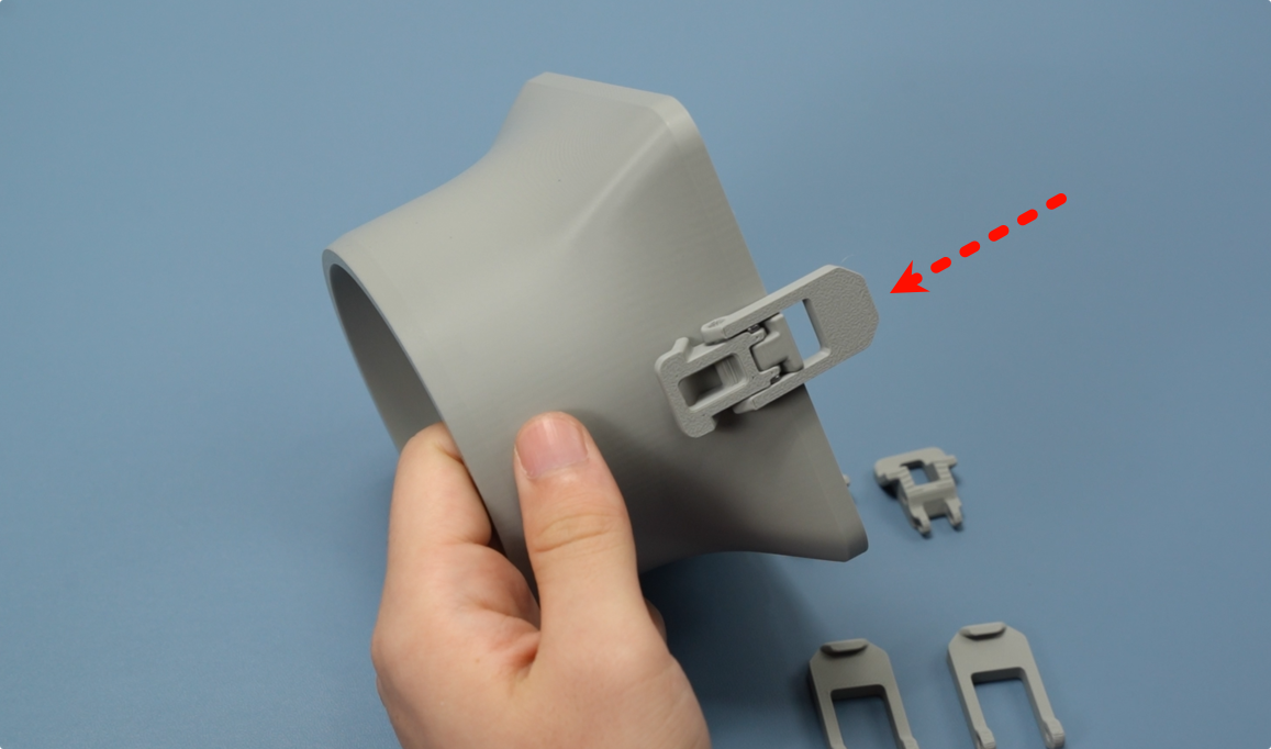
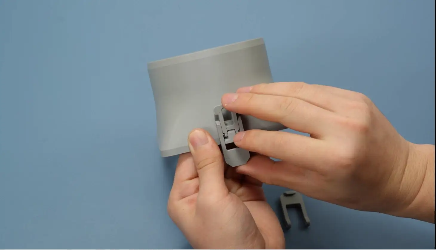
Insert the longer buckle part into one end of the shorter part, align their screw holes, and tighten the screws on the left and right sides to complete the assembly of the two buckle parts.
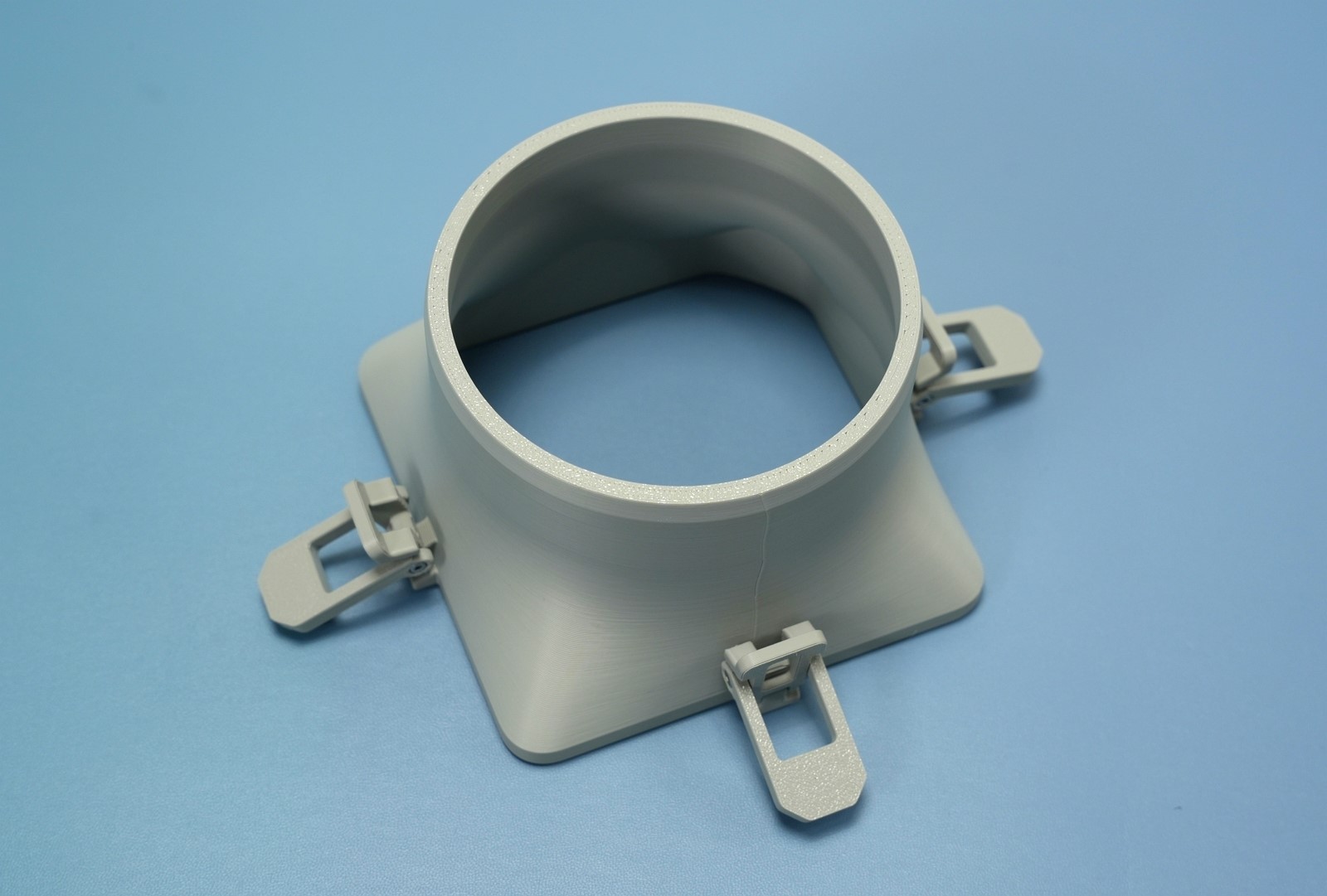
Move the buckle up and down by hand to check if it moves smoothly without jamming. Assemble three buckles in this way. The overall state after assembly can be referred to in the diagram below.
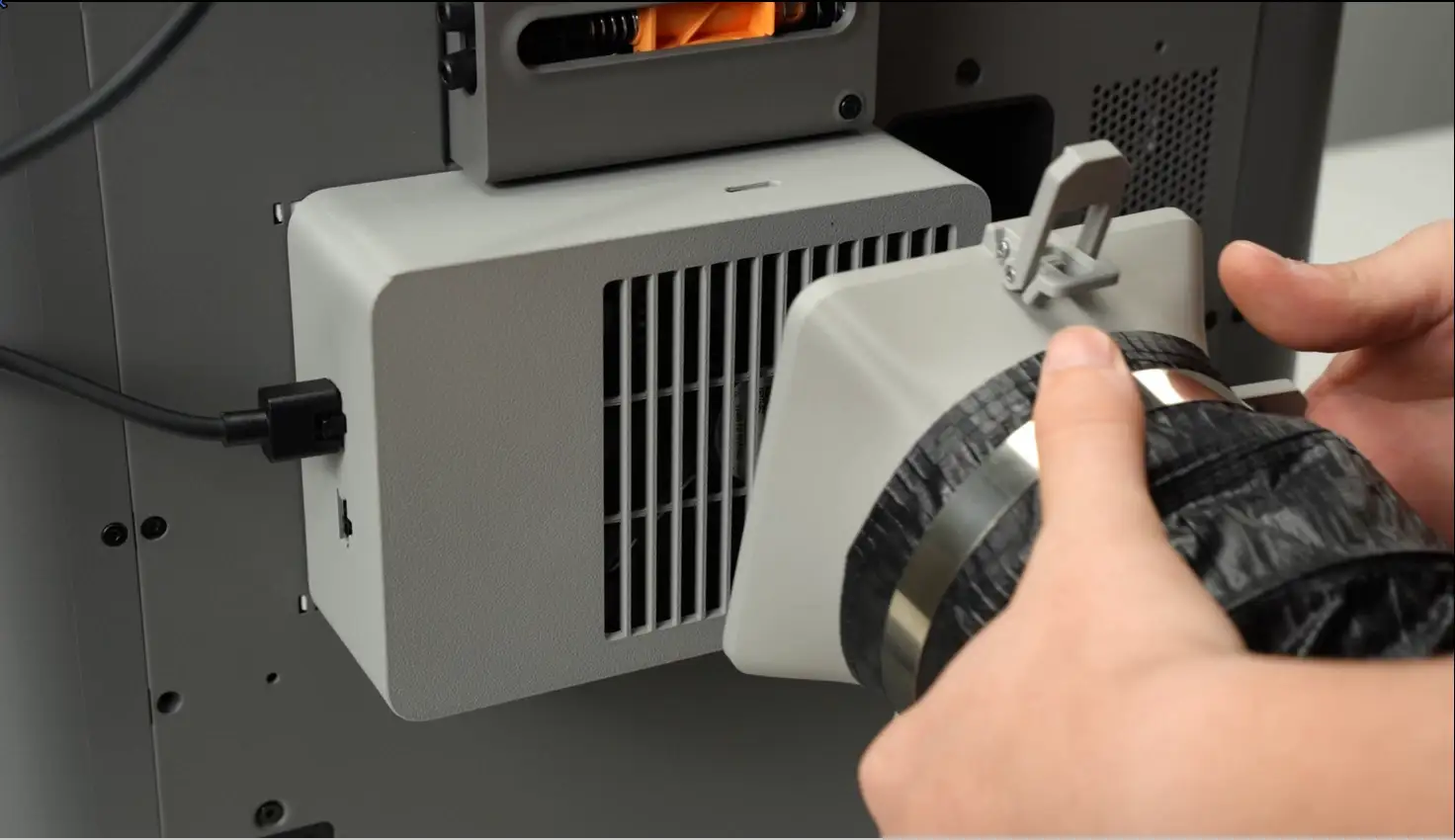
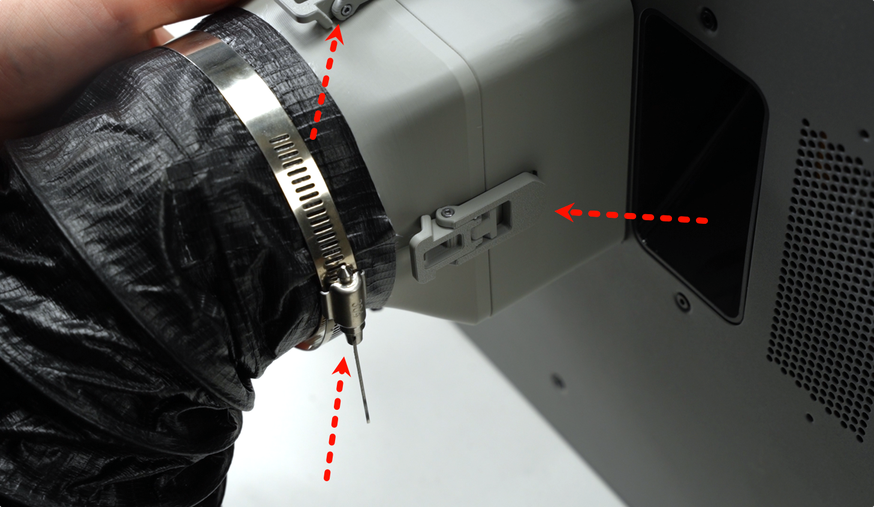
Slide one end of the exhaust pipe over the pipe connector and fix it with three-point buckling. It is recommended to fix the upper and lower buckles first, then the right buckle.