Você está no 3DFinder
Buscamos em Thingiverse, MakerWorld e Printables ao mesmo tempo para te dar o melhor de cada uma.
Descrição
(Expect a few updates over the coming days as I make sure to work out any bugs in the posting/files and update the description with additional information
Update1: Added the assembly manual in PDF Format!
Update2: Added the operating instructions and fixed a bug with the LEDs. They light correctly now!).
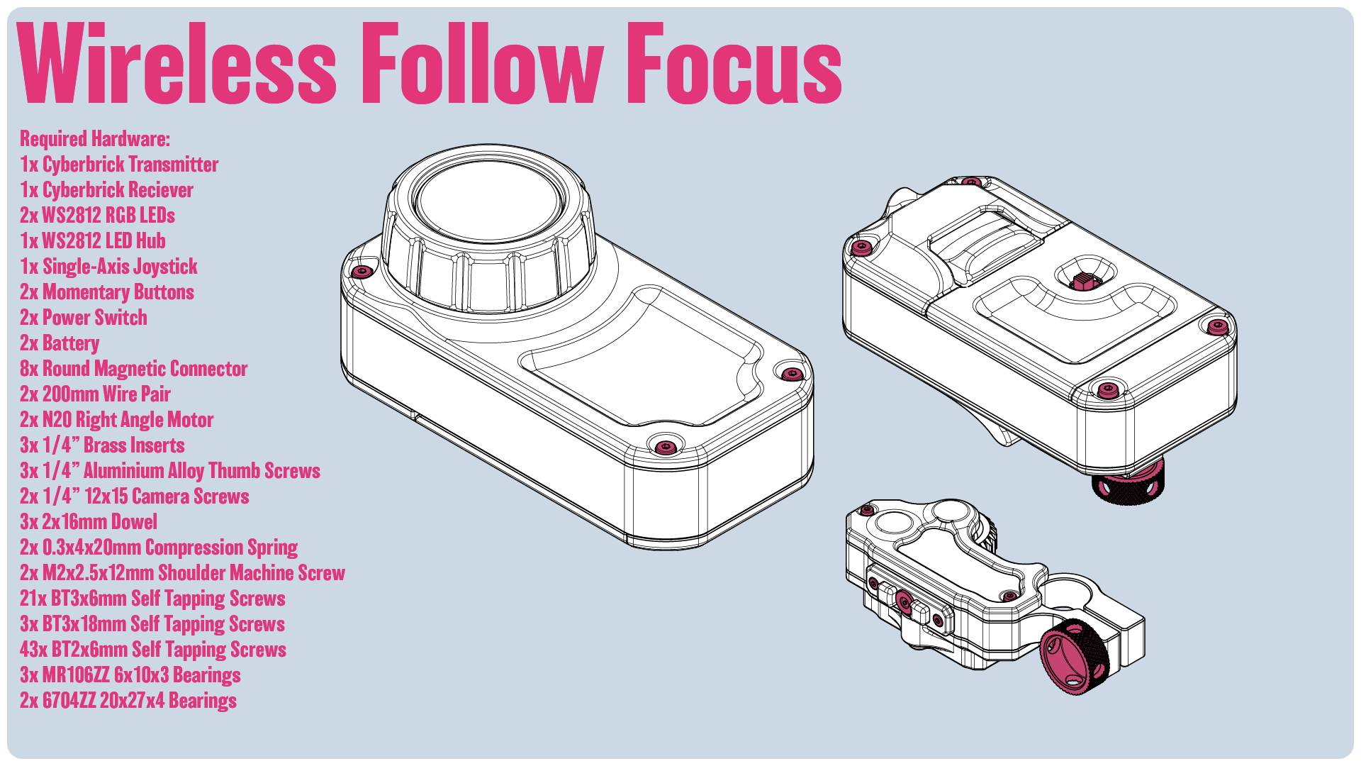
Introduction
Introducing my Wireless Follow Focus system, driven by the Cyberbrick Hardware!
I've been starting to make videos and had a need for a wireless follow focus system. This model was a blast to design and incorporated a few new interesting elements for me. It's driven fully by the Cyberbrick hardware. It allows for up to two motors which can be switched between. It also supports dual rates, for two motor speeds.
There are some limitations, as it is utilizing only hardware available on the Maker's Supply. So, it's not exactly like a high-end follow focus system. In particular, the knob doesn't rotate as such. More so it rocks a joystick back and forth. There's no real dial type controller for the Cyberbrick hardware, so this is one of the trade offs. It doesn't allow for as dynamic of focus shifting, but for more static shots, deliberate moves, or just tweaking the focus, it is nice.
The controller has two buttons which are used to switch which motor is being controlled, and at which speed it rotates at max. It is using a script to control this, so there is a slight delay. On the receiver there are 2 LEDs to help visually indicate which mode the receiver is in.
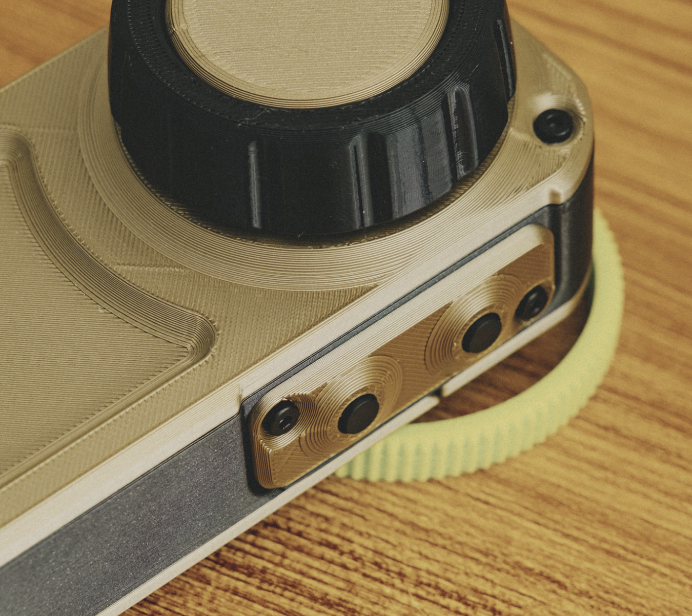
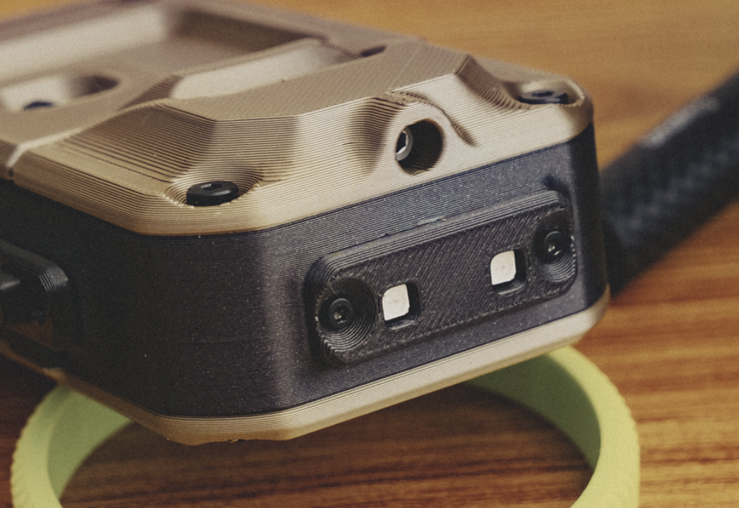
On the receiver itself, there's two back plate options for different mounting options. The first option allows the use of ¼" screws to easily attach to a standard cage. The second option offers a 15mm rod mount.
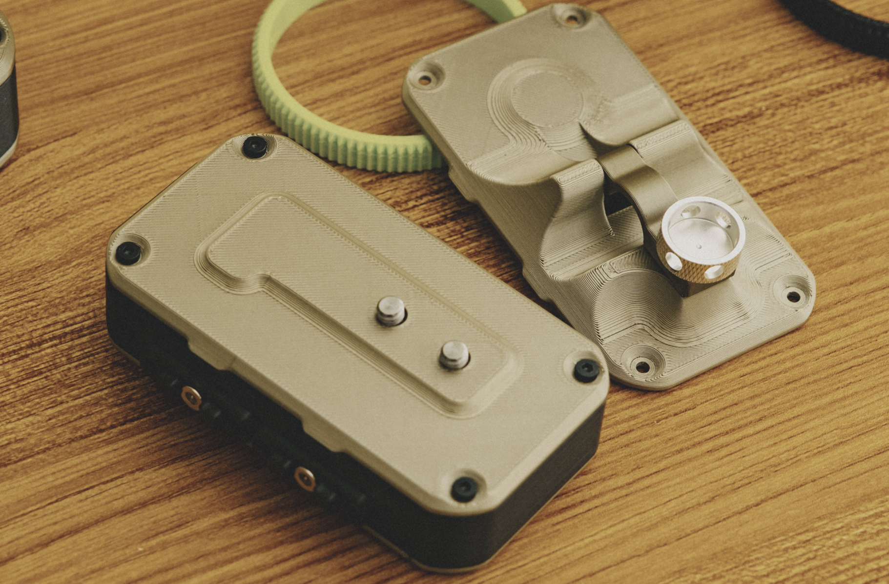
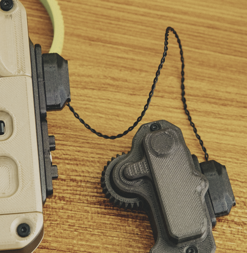
The motors use the round magnetic connectors to connect to the receiver, offering a quick and secure connection.
Usage
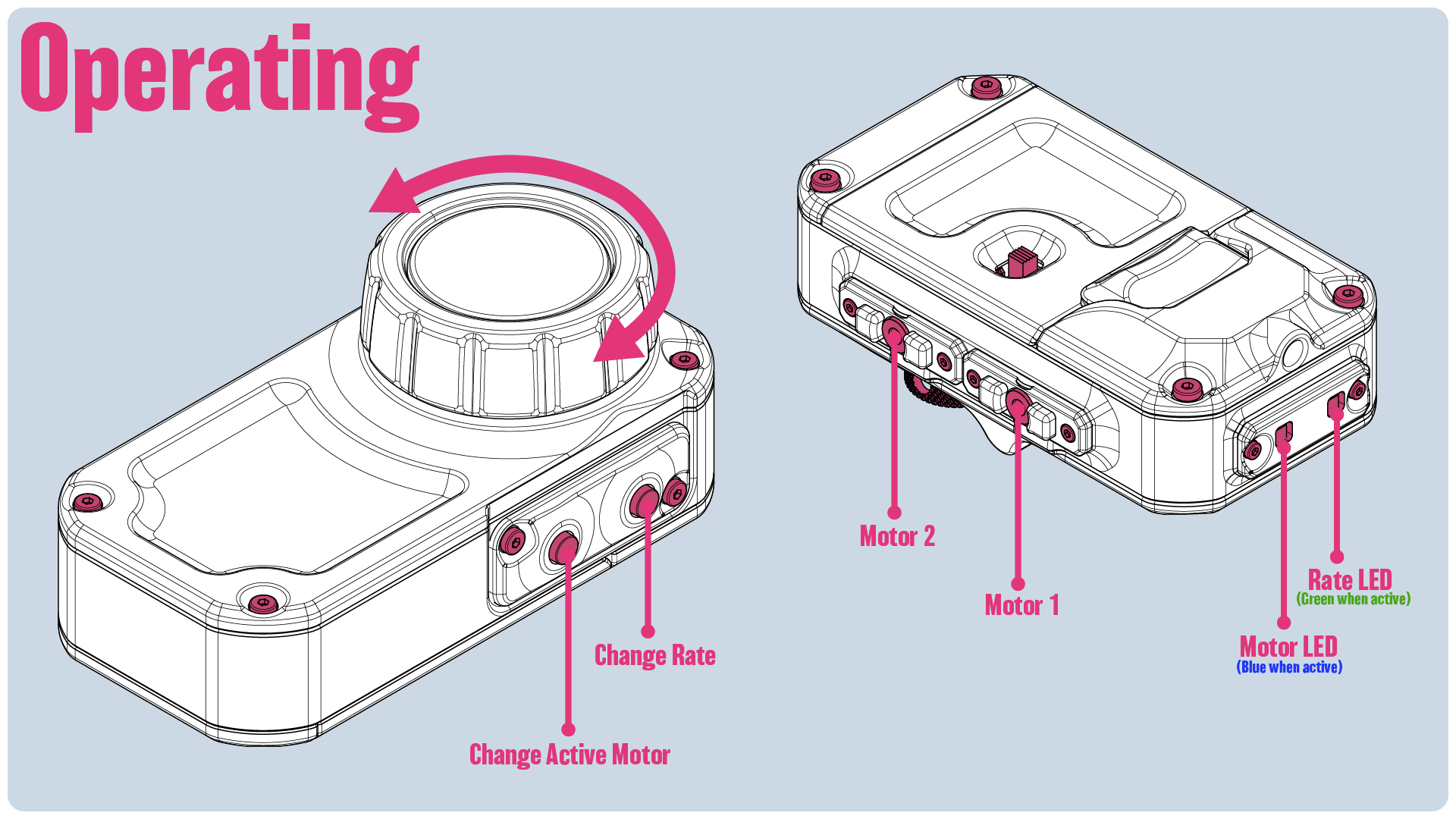
Rotate the main knob to move the active motor forward or backwards.
Pressing the Change Active Motor button switches between the two motors. When the second motor is active, the indicated LED on the receiver will turn blue. When the first motor is active, it’ll be off.
Pressing the Change Rate button changes the top speed of the motor, allowing for finer control. When in the slower rate, the indicated LED on the receiver will be green. When the motor is at it’s full speed, the LED will be off.
Printing & Filaments & Hardware
Printing:
I split the plates up for a two color design that should fit the A1 Mini fine. For my own model, I printed the knob itself in TPU, but for the plates uploaded to Bambu, I've left it as PLA. If you've got some TPU though, you might want to consider printing it in TPU.
Featured Filaments:
Bambu PLA Iridium Gold Metallic
Bambu PLA Iron Gray Metallic
Bambu 95A HF TPU
Hardware:
1x Cyberbrick Transmitter
1x Cyberbrick Reciever
2x WS2812 RGB LEDs
1x WS2812 LED Hub
1x Single-Axis Joystick
2x Momentary Buttons
2x Power Switch
2x Battery
8x Round Magnetic Connector
2x 200mm Wire Pair
2x N20 Right Angle Motor
3x 1/4” Brass Inserts
3x 1/4” Aluminium Alloy Thumb Screws
2x 1/4” 12x15 Camera Screws
3x 2x16mm Dowel
2x 0.3x4x20mm Compression Spring
2x M2x2.5x12mm Shoulder Machine Screw
21x BT3x6mm Self Tapping Screws
3x BT3x18mm Self Tapping Screws
43x BT2x6mm Self Tapping Screws
3x MR106ZZ 6x10x3 Bearings
2x 6704ZZ 20x27x4 Bearings
Assembly Instructions
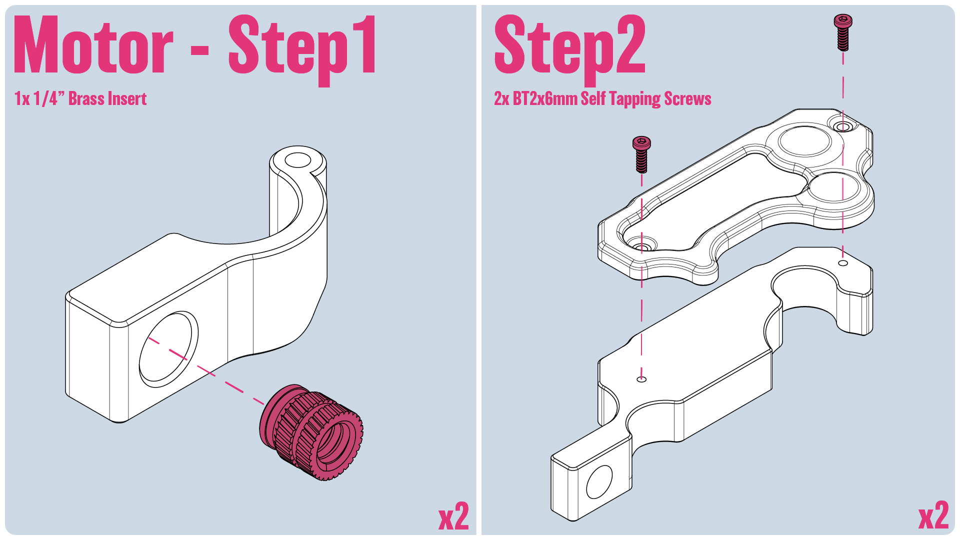
Step1: We'll insert a ¼" 8x8 Brass Insert into the hinge. It should go in the top, as there's a slight lip on the bottom side that helps prevent the brass insert from pulling all the way through when tightened down
Step2: Screw the flat side to the mid section using 2 BT2x6mm Self Tapping Screws
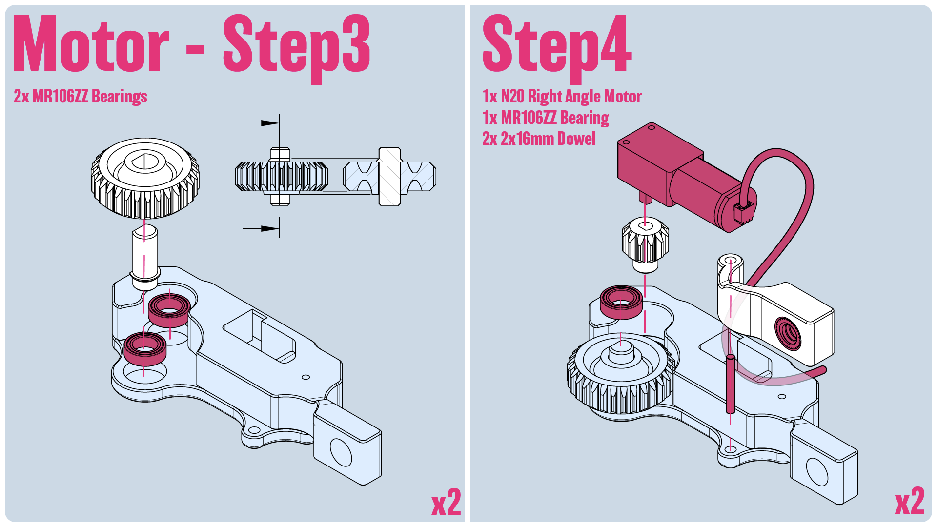
Step3: We'll insert two MR106ZZ Bearings along with the large gear. Pay attention as the large gear isn't perfectly symmetrical. One side protrudes out. With the central axle in place, it should provide a slight protrusion on both sides that helps center it between the bearings
Step4: Install the small gear onto the N20 Right Angle Motor. We'll also run a wire for the motor down and out the side hole. Keep it tight, as the lid fits tight.
Additionally we'll install the another MR106ZZ Bearing on top of the large gear and a D2x16mm Dowel along with the hinge piece we assembled in the first step.
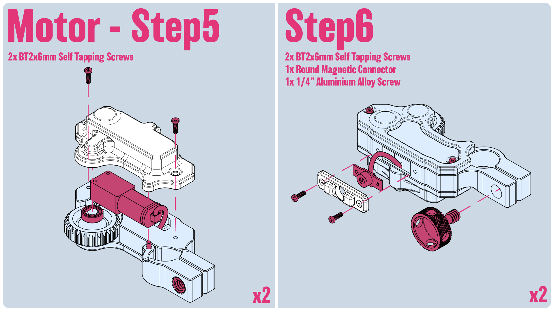
Step5: We'll secure the top plate in place using 2 BT2x6mm Self Tapping Screws
Step6: We'll plug the Round Magnetic Connector into the Motor wire. Keep in mind that there's and A and B side to the Round Magnetic Connectors, so make sure you use the appropriate ones for how you wish to configure your model. Once it's plugged in, just kind of jam it in and secure it in place using the plate. Lastly, secure the 15mm rod clamp by inserting a ¼" Thumb screw into the hinge portion of the motor.
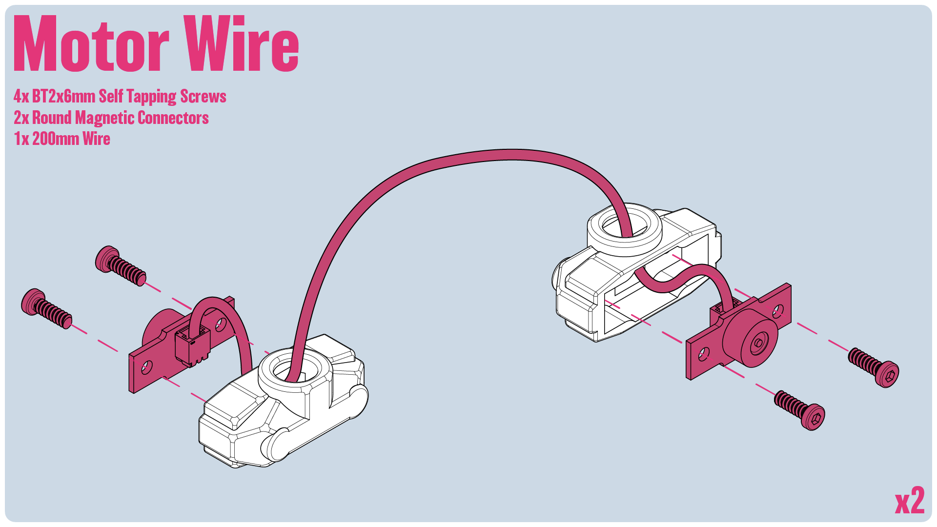
Motor Wires: For each wire, we'll use 2 Round Magnetic Connectors. Feed the 200mm wire through the plastic housing and secure it to the Magnetic Connector, then screw the connectors into place with 2 BT2x6mm Screws on either side. Keep in mind that the Magnetic Connectors have an A and B side, so be mindful of which ones you're using on the receiver/motors, and which ones you're using on the wires.
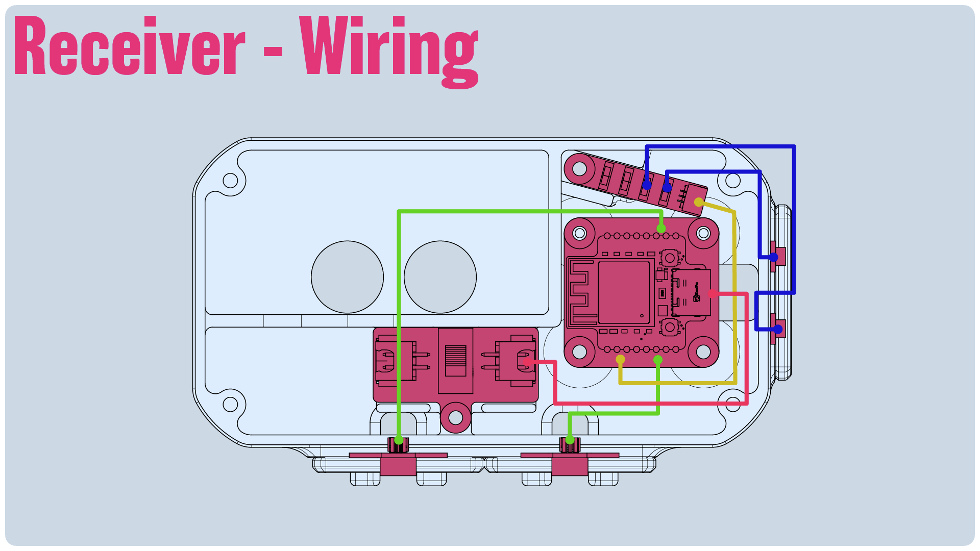
Receiver Wiring: Before we get started on the Receiver, we'll want to make sure we reference this wiring guide as we assembly the components.
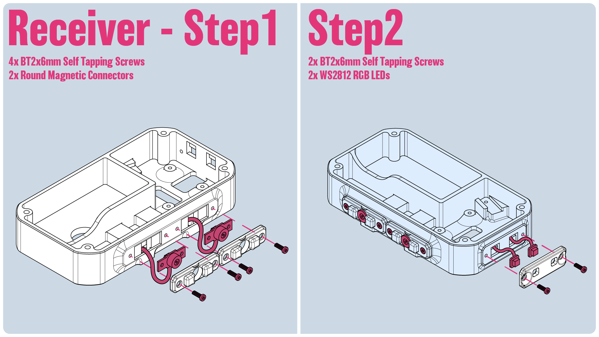
Step1:First we'll install two Round Magnetic Connectors on the side, making sure the wires are flowing down. Secure them in place using the plates like we did with the motor, using 4 BT2x6mm Self Tapping Screws
Step2: For the LEDs, we want the wires to flow upwards. Secure them in place using the plate and 2 BT2x6mm Self Tapping Screws
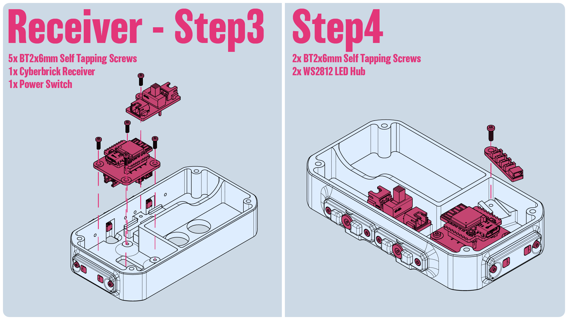
Step3: We'll install the Cyberbrick Receiver and Power Switch at this stage using 5 BT2x6mm Self Tapping Screws. Refer to the wiring guide and make sure all the wires are connected to the receiver. That includes the wire that'll go to the LED Hub we'll install in the next step.
Step4: Install the LED Hub, securing it with a BT2x6mm Self Tapping Screw. Make sure it's plugged into the receiver before installing the HUB, then install the connectors for the LEDs, referencing the wiring guide for which LEDs connect to which slots.
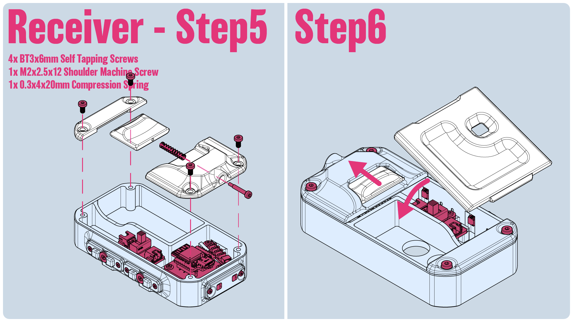
Step5:Time to install the front cover. We'll secure the latch in place using a M2x2.5x12mm Socket Head Shoulder Machine Screw and a .3x4x20mm Spring! Then screw both the top and bottom sections in using 4 BT3x6mm Self Tapping Screws
Step6: Install the cover by pulling back the latch, inserting the cover into the grove at the base, and just pushing it into plate.
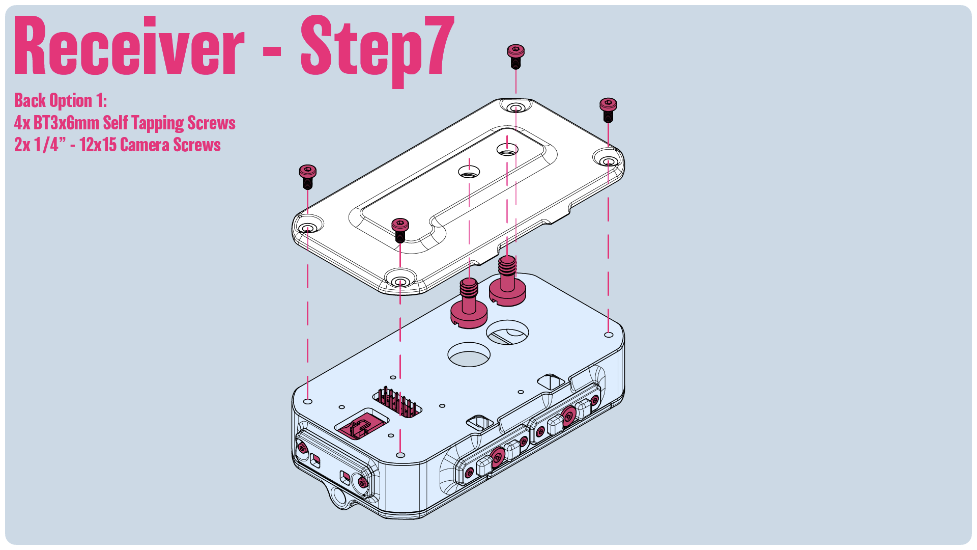
Step7: For Back Option 1, we just need two ¼" 12x15 Camera screws. The back cover has modeled in ¼" threads that you'll have to push/screw the ¼" screws though. Once all the way in and past the short thread section, it'll help keep them from falling out. Secure the back plate in place using 4 BT3x6mm Self Tapping Screws
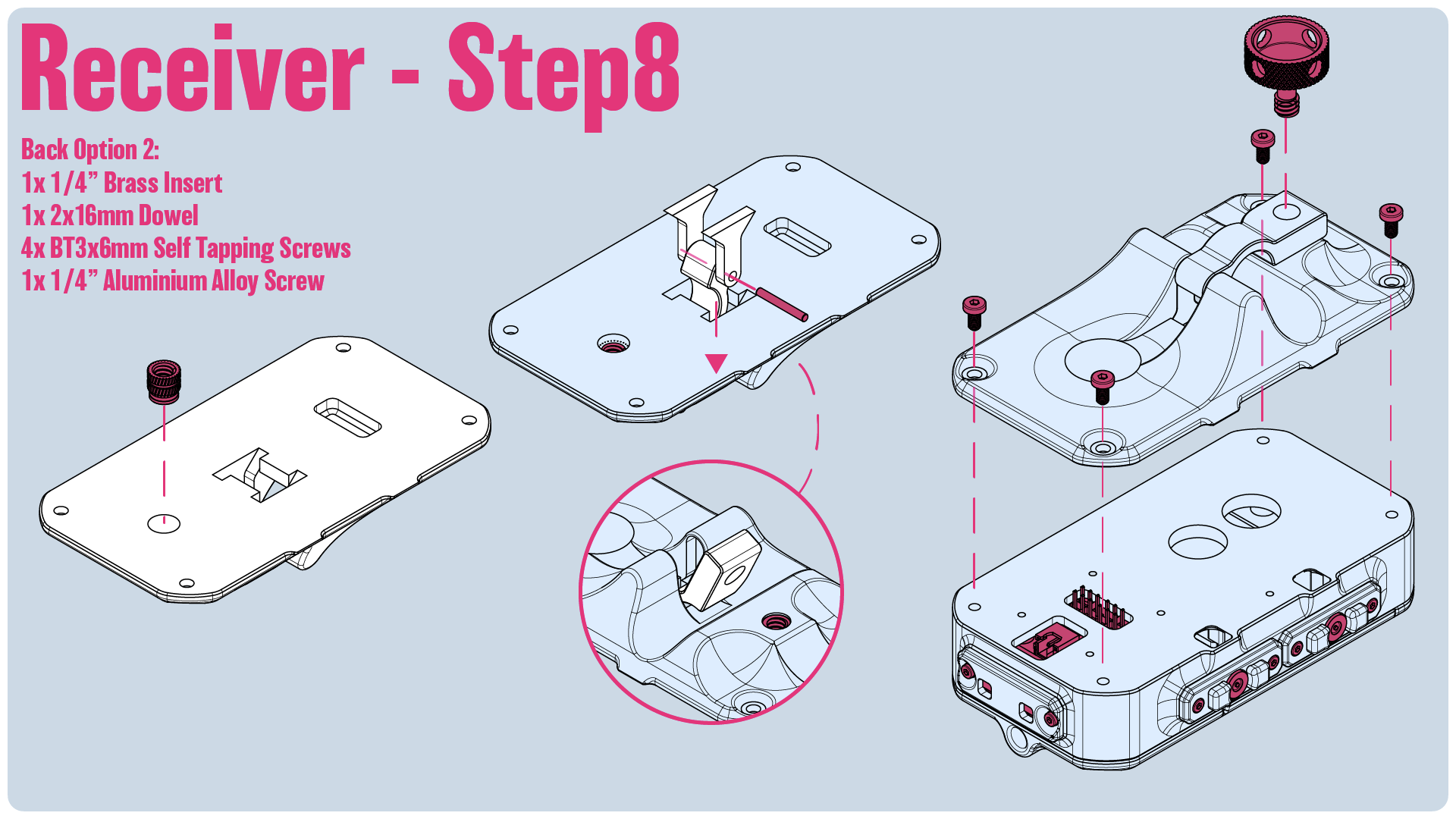
Step8: For the 15mm mount option, there's a couple more steps.
Firstly, we'll want to insert the ¼" brass insert. There's a lip like on the hinge for the motor, so we'll want to insert the brass insert from the back and make sure we seat it all the way fully against the lip on the front edge.
Secondly, we'll take the hinge for the receiver and push it through the hole in the back plate. On either side, we'll pin the two little A frame pieces with a D2x16mm Dowel, and then pull it through.
Lastly, we'll secure it in place using 4 BT3x6mm Self Tapping Screws.
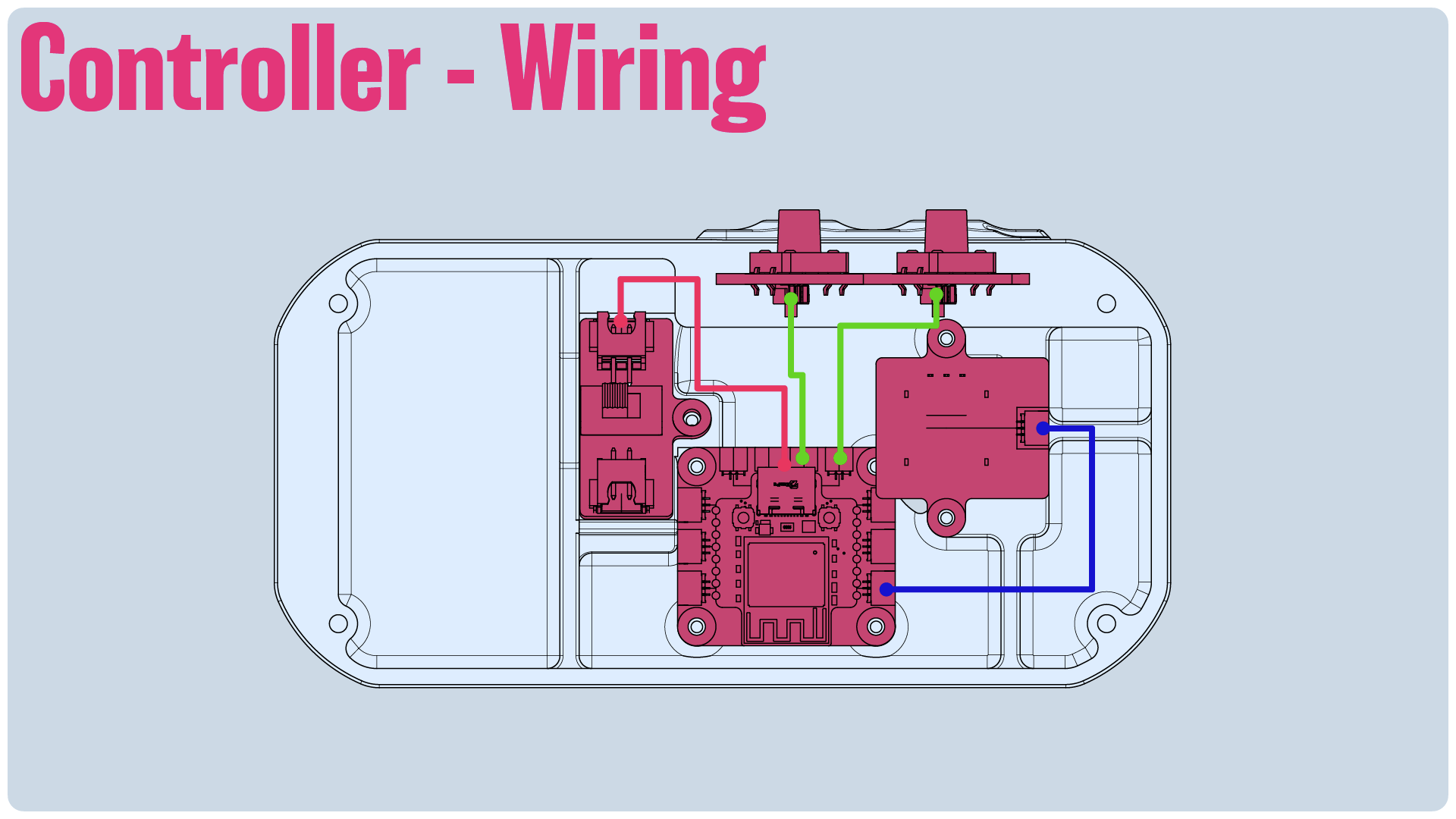
Controller Wiring: Like with the Receiver, we'll want to reference this guide for the wiring as we assemble the model.
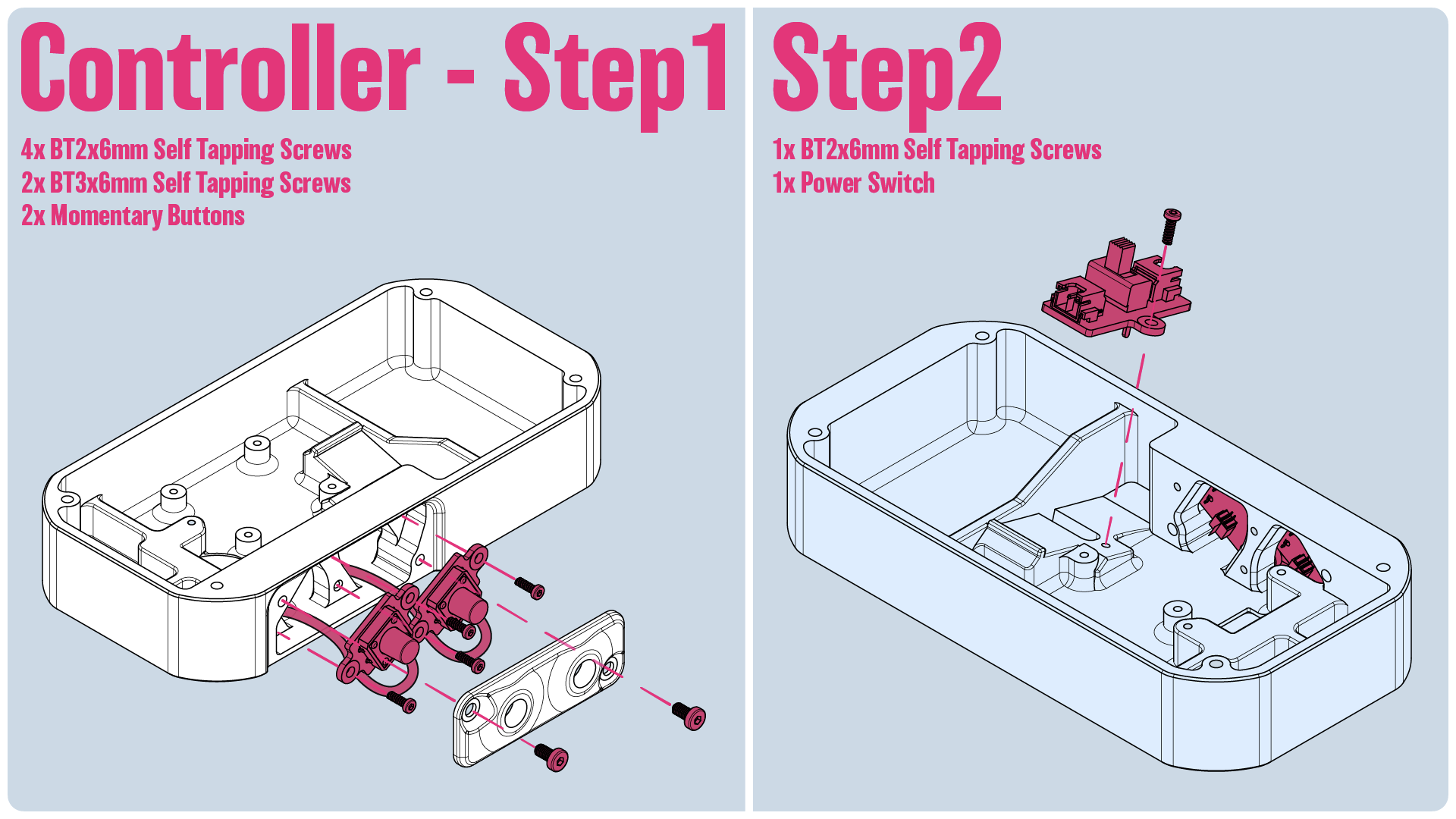
Step1: We'll install 2 Momentary Buttons with the wires flowing down, securing them in place with 4 BT2x6mm Self Tapping Screws. Install the top plate in place using 2 BT3x6mm Self Tapping Screws
Step2: Install the Power switch and secure it with a BT2x6mm Self Tapping Screw. Make sure the power wire leading to the transmitter is installed.
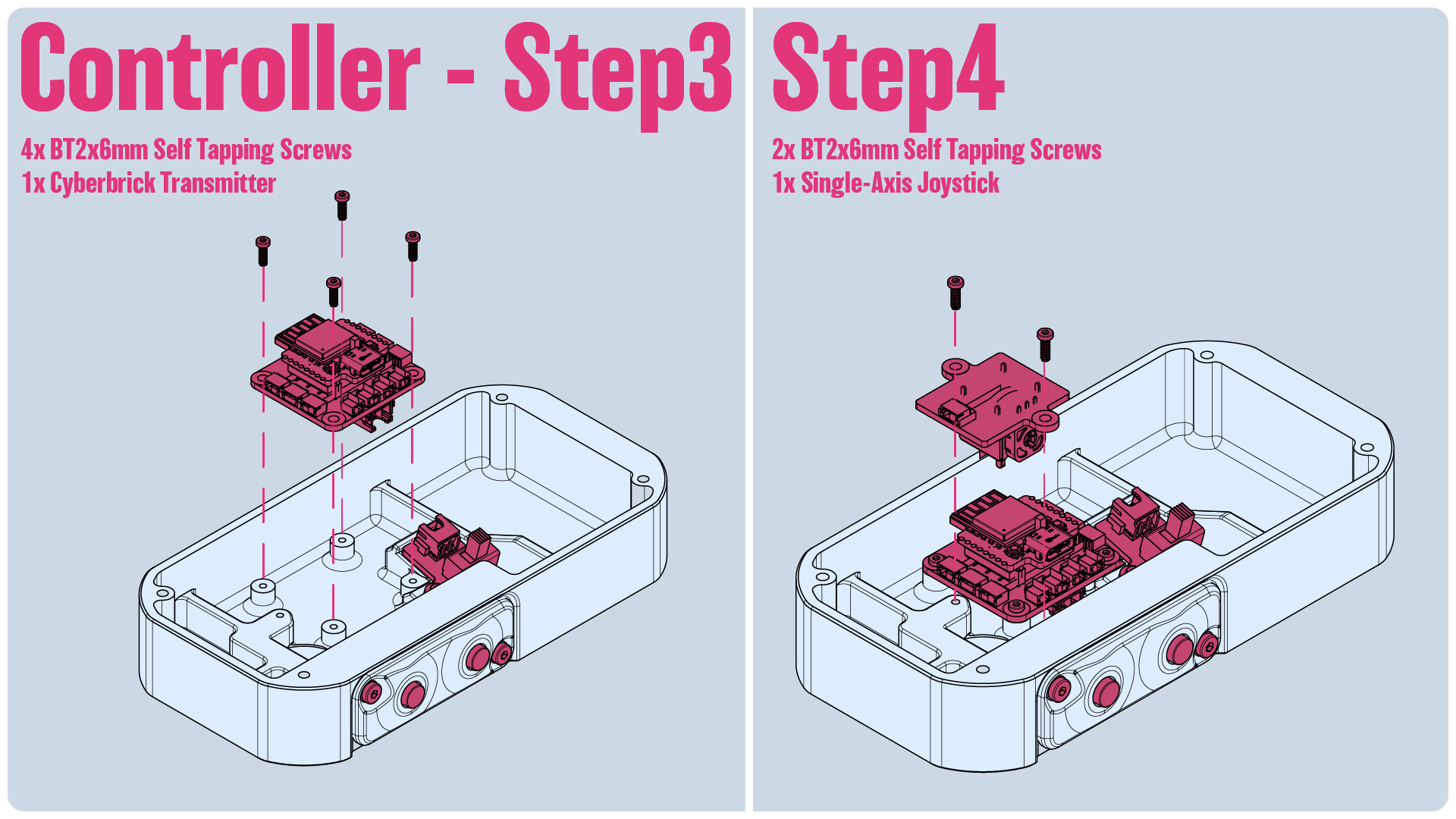
Step3: Next we'll install the Cyberbrick Transmitter. Make sure the you connect the wires for the buttons and power switch. Additionally, pre-connect the wire for the joystick. Secure it in place using 4 BT2x6mm Self Tapping Screws.
Step4: Install the joystick face down with the wire facing towards the top of the controller. Secure it in place using 2 BT2x6mm Self Tapping Screws
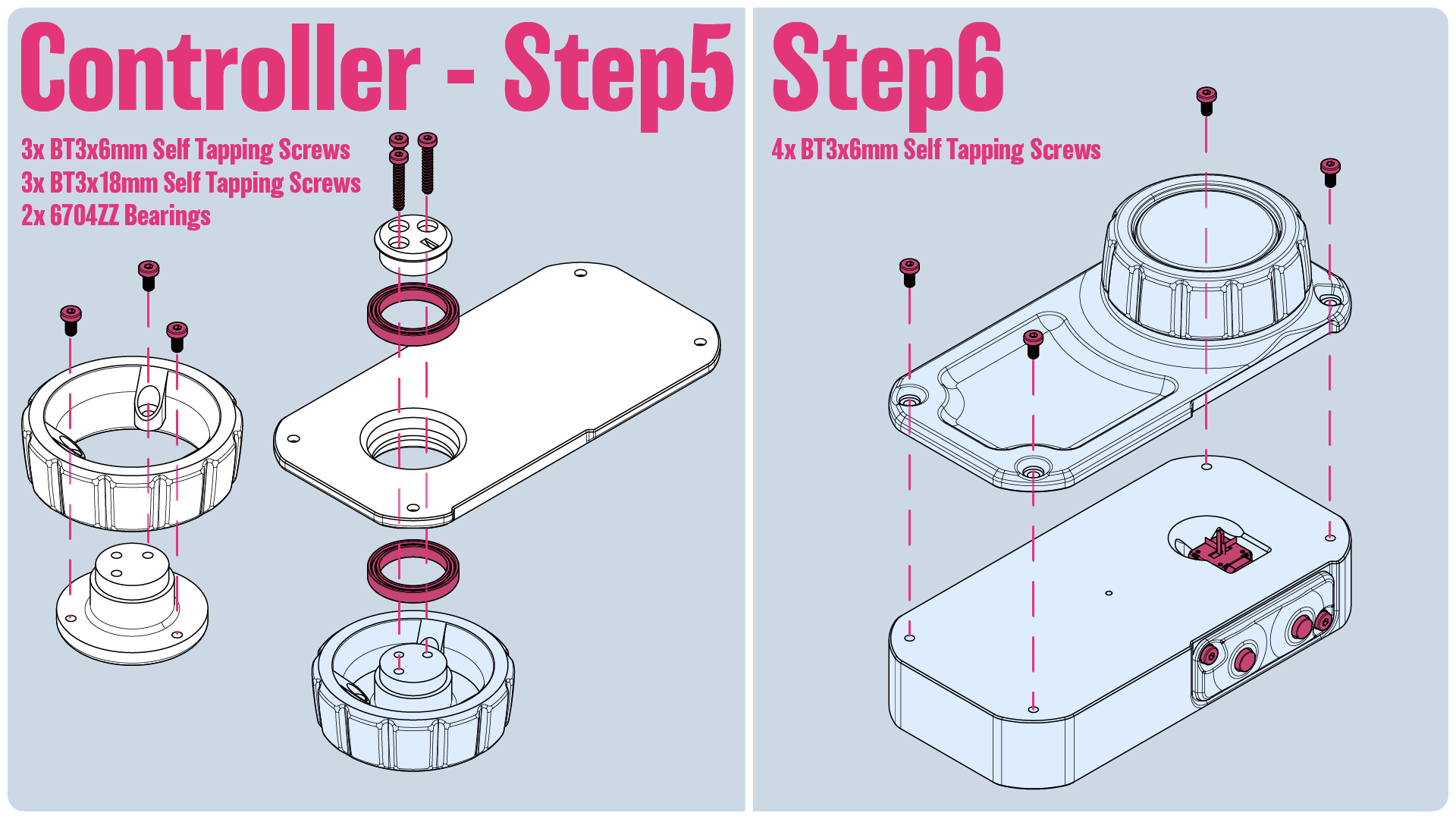
Step5: Secure the outer knob to the top plate using 3 BT3x6mm Self Tapping Screws. We'll then sandwich the top plate between two 6704ZZ bearings and the top and bottom plates of the knob. Secure it all with 3 BT3x18mm Self Tapping Screws.
Step6: Align the slot in the knob so it aligns with the joystick and secure the front plate in place with 4 BT3x6mm Self Tapping Screws
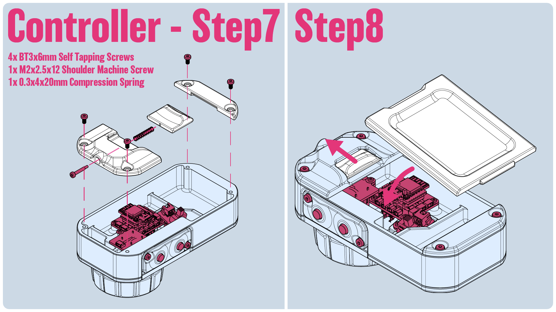
Step7:Time to install the back cover. We'll secure the latch in place using a M2x2.5x12mm Socket Head Shoulder Machine Screw and a .3x4x20mm Spring! Then screw both the top and bottom sections in using 4 BT3x6mm Self Tapping Screws
Step8: Install the cover by pulling back the latch, inserting the cover into the grove at the base, and just pushing it into plate.
That's It!

Gostou deste modelo? Crie uma conta grátis para salvar seus favoritos e voltar a eles depois.
Criar conta