Você está no 3DFinder
Buscamos em Thingiverse, MakerWorld e Printables ao mesmo tempo para te dar o melhor de cada uma.
Descrição
Changelog
[1.2] - 2025-12-08
Added
- Added assembly guide video
[1.1] - 2025-12-05
Fixed
- Adjusted the M3 nut placement hole in the rear bracket and the M3 screw hole in the base cover for the M3 x 10 screw.
Added
- (Optional) The gear with tighter hole
[1.0] - 2025-12-01
Added
- Initial release
Introduction
When using 3D printers that support multiple AMS units and multiple nozzles (such as the H2D), the optimal material-saving configuration planned by the slicer software often requires switching filament spools that are already placed in the AMS (Automatic Material System) to another AMS assigned to a specific nozzle. This process of repositioning filament spools to different slots is often time-consuming and cumbersome.
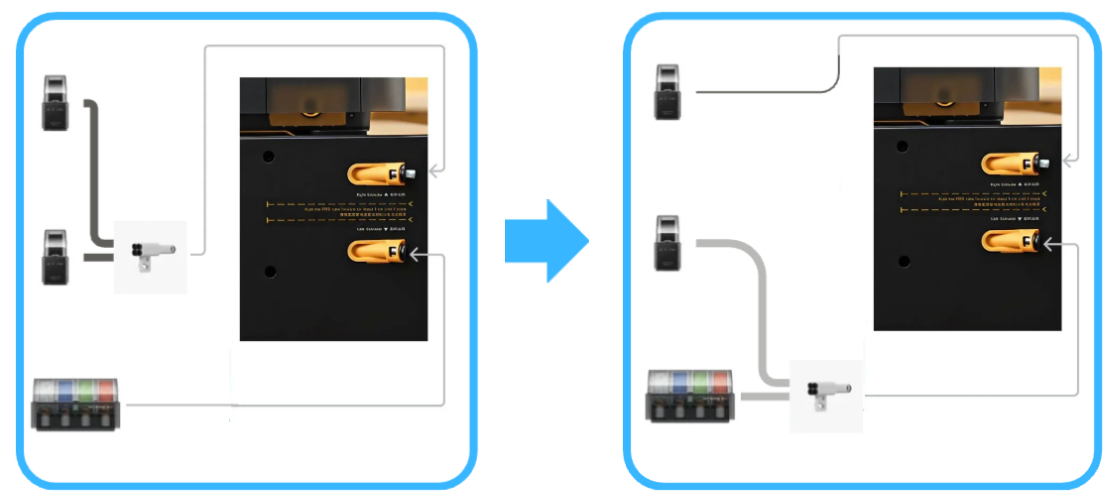
For example, you have AMS2pro and two AMS HT units, each connected to one of H2D's two nozzles (left side of the diagram), and you have already loaded 6 different colored filaments in the previous printing job. In a new printing task, the slicer software executes slicing in Filament-Saving Mode and requires allocating 5 colors to one of the nozzles. Therefore, for optimal material-saving settings, you must switch one AMS HT and the 4-in-1 PTFE adapters to the other nozzle (right side of the diagram), which is quite inconvenient. Of course, you can choose Convenience Mode, but this will sacrifice some material. Why not have your cake and eat it?
To address this issue, I came up with the idea of creating an AMS Multiple Nozzle Switch System. While printing a stacking system for my multiple AMS units, I discovered that although MakerWorld already has excellent nozzle management systems, achieving the switching convenience I envisioned with the increasing number of AMS units requires integrating a multiple nozzle switch system into the AMS stacking system. Therefore, I designed this AMS Multiple Nozzle Switch System.
Key Features
- Provides the ability for AMS units on AMS stacking systems to quickly switch to different nozzles
- Supports AMS using PTFE feed tubes, including but not limited to Bambu Lab's AMS
- Currently provides 1-in-2-out or 1-in-4-out nozzle switch modules. If you have multiple printers, you can quickly switch PTFE tubes to another printer (you still need to manually switch the AMS 6-pin Cable) in order to save you time
- Extended knob design: To adapt to AMS stacking systems on MakerWorld, the switching knob extends from the rear to the front for easier nozzle switching
- Uses ceramic feed ports to ensure smooth feeding while reducing wear caused by high-hardness filaments (such as filaments containing carbon fiber or glass fiber)
The switching knob is positioned closer to its connected AMS, making it easier to identify
Compatible AMS Stacking Systems
The AMS Multiple Nozzle Switch System is designed to be installed on AMS stacking systems. The following is the current list of compatible systems:
AMS 1 & 2 Pro & HT Modular Sliding Stacking System - By Shuwn Hsu - Included in this model
Printing Instructions
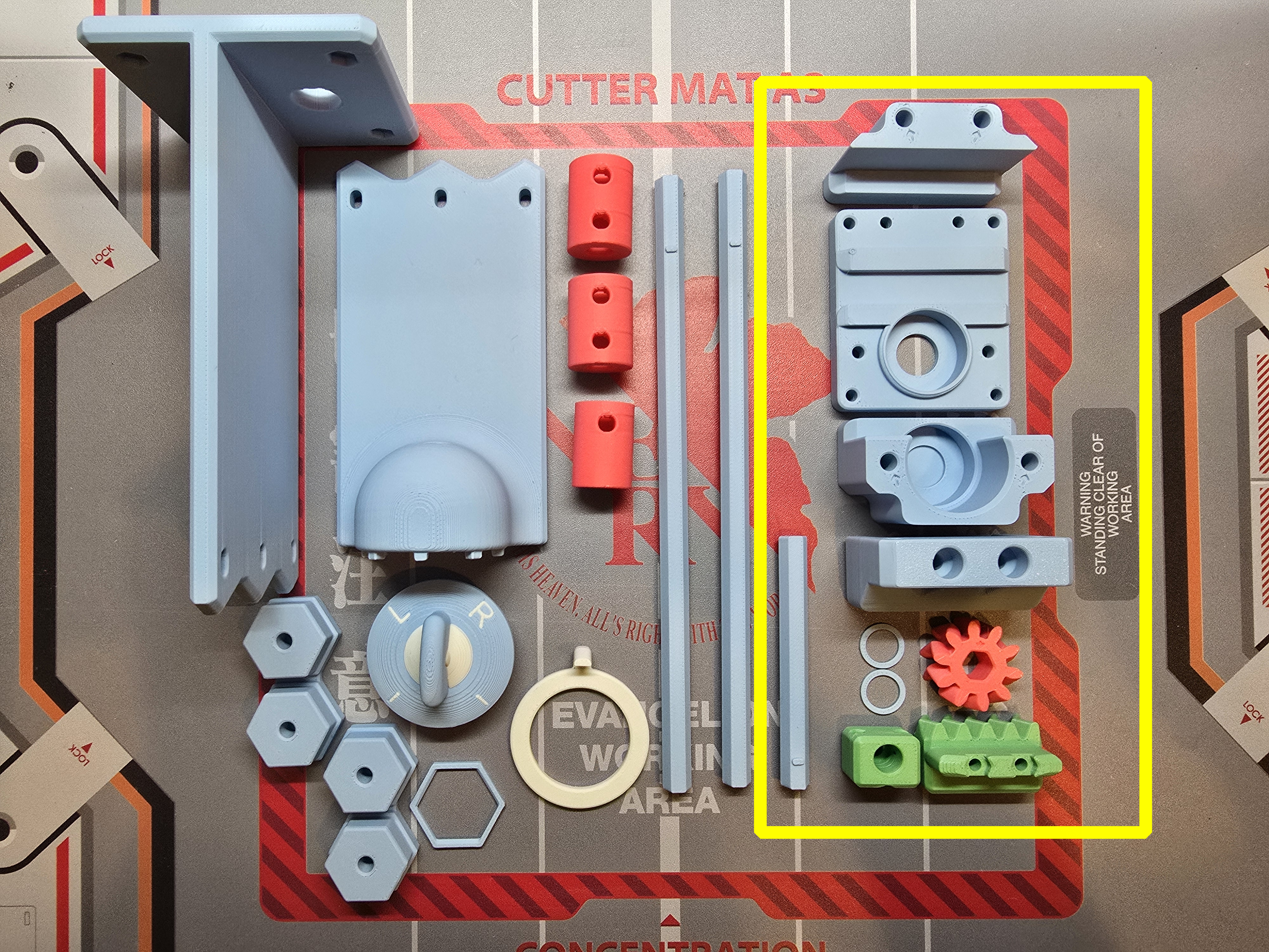
This project consists of two types of components: the core component and multiple AMS stacking mount components.
Core Component:
Includes:
- Plate 1: Nozzle switch unit body
- Plate 2, Plate 3: Knobs
- Plate 4: Test part
- Plate 5, Plate 6: Nozzle switch module
- Plate 10: (Optional) The gear with tighter hole
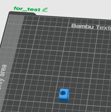
Before printing the core components, you can first print this part as a hole diameter test part,
After printing the test part, try inserting the ceramic eye from the outside into the hole to test the hole diameter. If it can be inserted smoothly, it's fine. If it's very difficult to insert, please calibrate your printer's flow rate and shrinkage.
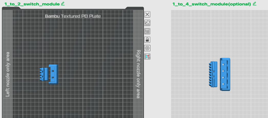
The nozzle switch module has been pre-designed with 1-in-2-out and 1-in-4-out options. Please print one according to your needs.
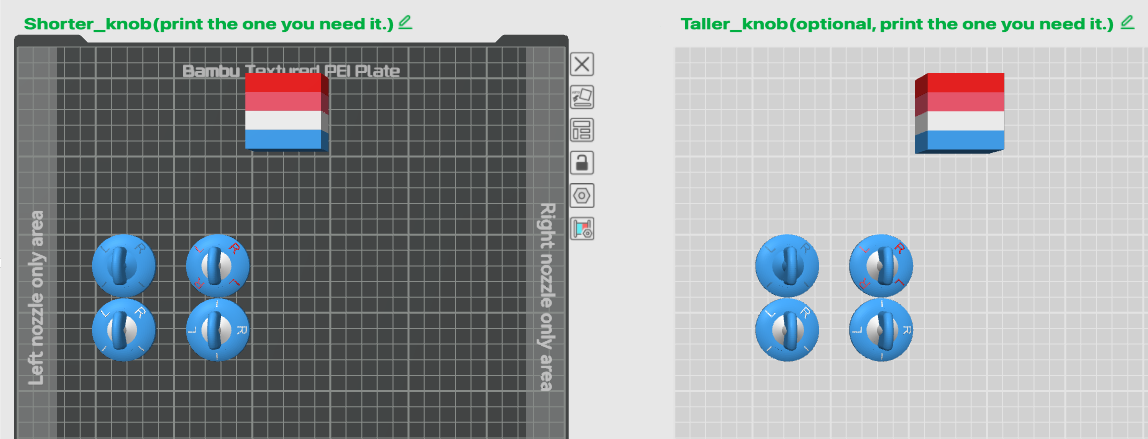
The knob section has been pre-designed with multiple styles, corresponding to different output nozzle names. The left plate has shorter knobs that won't protrude too much, while the right plate has taller knobs for better grip; each plate contains the two parts on the left are " LR | | " knobs for dual switching, and the two parts on the right are "L | R | " and "LRLR" knobs for 4-way switching. You can print the required knob according to your needs.
AMS Stacking System Mount Component:
*The nozzle switch unit body is not designed to work alone. You also need to pair with and select an AMS stacking system mount to achieve convenient switching.
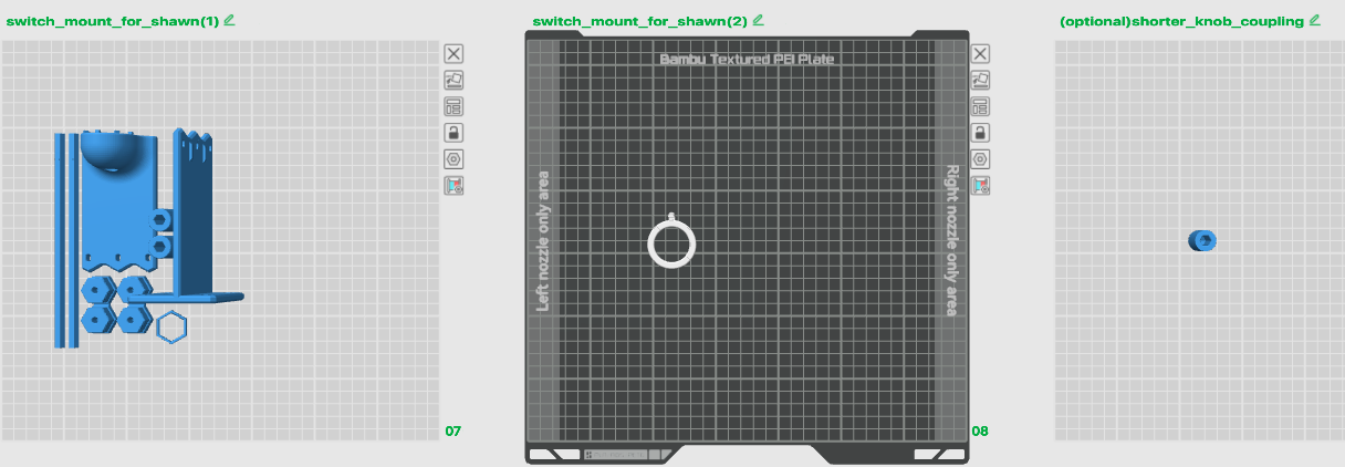
Plate contains:
- Plate 7: Extended axis rod and mount for AMS Stacking System by Shuwn Hsu
- Plate 8: Knob Pointer
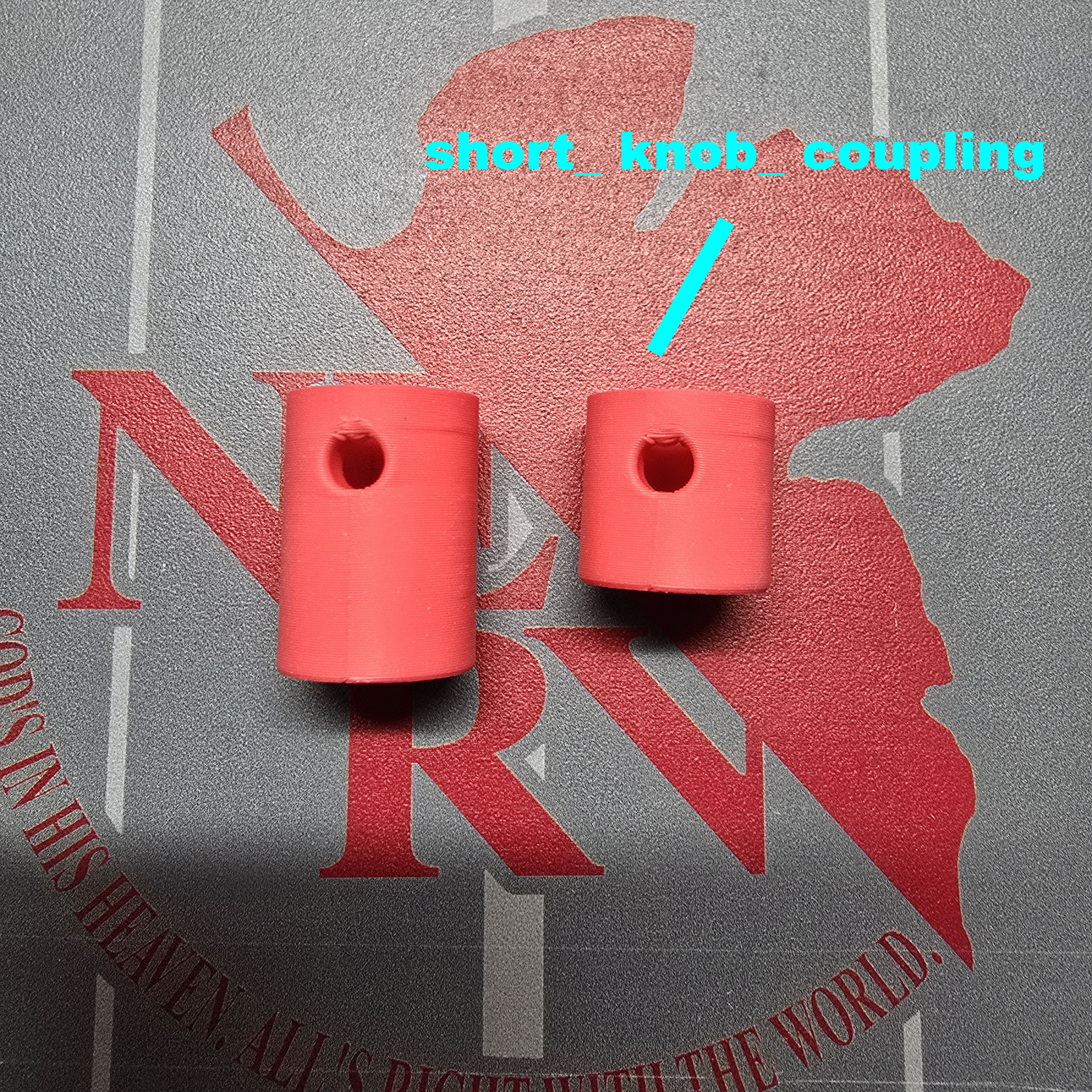
- Plate 9: (Optional) Shorter knob coupler, for more compact knob assembly
Currently, one version of the mount has been pre-designed for use with the AMS 1 & 2 Pro & HT Modular Sliding Stacking System - By Shuwn Hsu
If you happen to have this AMS stacking system, you only need to print this mount to secure the core component - nozzle switch unit to your AMS stacking system.
More mounts for different placement positions or corresponding to different AMS stacking systems can be added in the future.
Parts Purchase List
* The Bill of Materials (BOM) above can only include some parts. Please refer to this Parts Purchase List for the remaining required parts
• Core Component - Nozzle Switch Unit
| Part Name | Quantity | Reference Purchase Link |
| ID 2.5mm x OD 4mm PTFE Tubes | Adjust as needed | Bambu Lab Official |
| Bambu 4-in-1 PTFE Adapter | At least 2 | Bambu Lab Official |
| M3 x 10 Flat Head Cap Machine Screws (FHCS) | 4 | Bambu Lab Official |
| M3 x 16 Button Head Cap Machine Screws (BHCS) *1 | 2 | Bambu Lab Official |
| M3 x 25 Button Head Cap Machine Screws (BHCS) *1 | 2 | Bambu Lab Official |
| D10x2 mm Round Magnet *2 | 3 (1-in-2-out) / 5 (1-in-4-out) | Bambu Lab Official / Shopee |
| PC4-M6 Pneumatic Connector for PTFE Tube *2 | 3 (1-in-2-out) / 5 (1-in-4-out) | Bambu Lab Official / Shopee |
| M3 Hex Nut | 2 | Bambu Lab Official |
| 608ZZ Ball Bearing | 2 | Bambu Lab Official |
| M3 X 4 - OD5 Round Threaded Brass Heat-Insert Nut | 6 | Bambu Lab Official / Shopee |
| M6 X 6 - OD8 Round Threaded Brass Heat-Insert Nut *2 | 3 (1-in-2-out) / 5 (1-in-4-out) | Amazon / Taobao / Shopee |
| OD3.9 x H6 x ID2.3 Ceramic Eye Aluminum Oxide Ceramic Head *2 | 3 (1-in-2-out) / 5 (1-in-4-out) | eBay / Taobao / Shopee |
*1 Button Head Cap Machine Screws (BHCS) can also be replaced with Socket Head Cap Machine Screws (SHCS)
*2 The quantity depends on the nozzle switch module you choose (1-in-2-out or 1-in-4-out)
• AMS Stacking System Mount Component (Optional) - For use with AMS 1 & 2 Pro & HT Modular Sliding Stacking System - By Shuwn Hsu
| Part Name | Quantity | Reference Purchase Link |
| M3 x 10 Button Head Cap Machine Screws (BHCS) *3 | 8 | Bambu Lab Official |
| M3 x 6 Button Head Cap Machine Screws (BHCS) *4 | 6 | Bambu Lab Official |
| M3 X 4 - OD5 Round Threaded Brass Heat-Insert Nut | 10 | Bambu Lab Official / Shopee |
| M3 Hex Nut | 4 | Bambu Lab Official |
| 608ZZ Ball Bearing | 1 | Bambu Lab Official |
*3 Button Head Cap Machine Screws (BHCS) can also be replaced with Socket Head Cap Machine Screws (SHCS)
*4 This screw is used for the extended axis rod coupler. It can also be replaced with M3 x 4 mm Hex Socket Set Screws (HSSS) to make the screw surface of the coupler more flush
Tools List
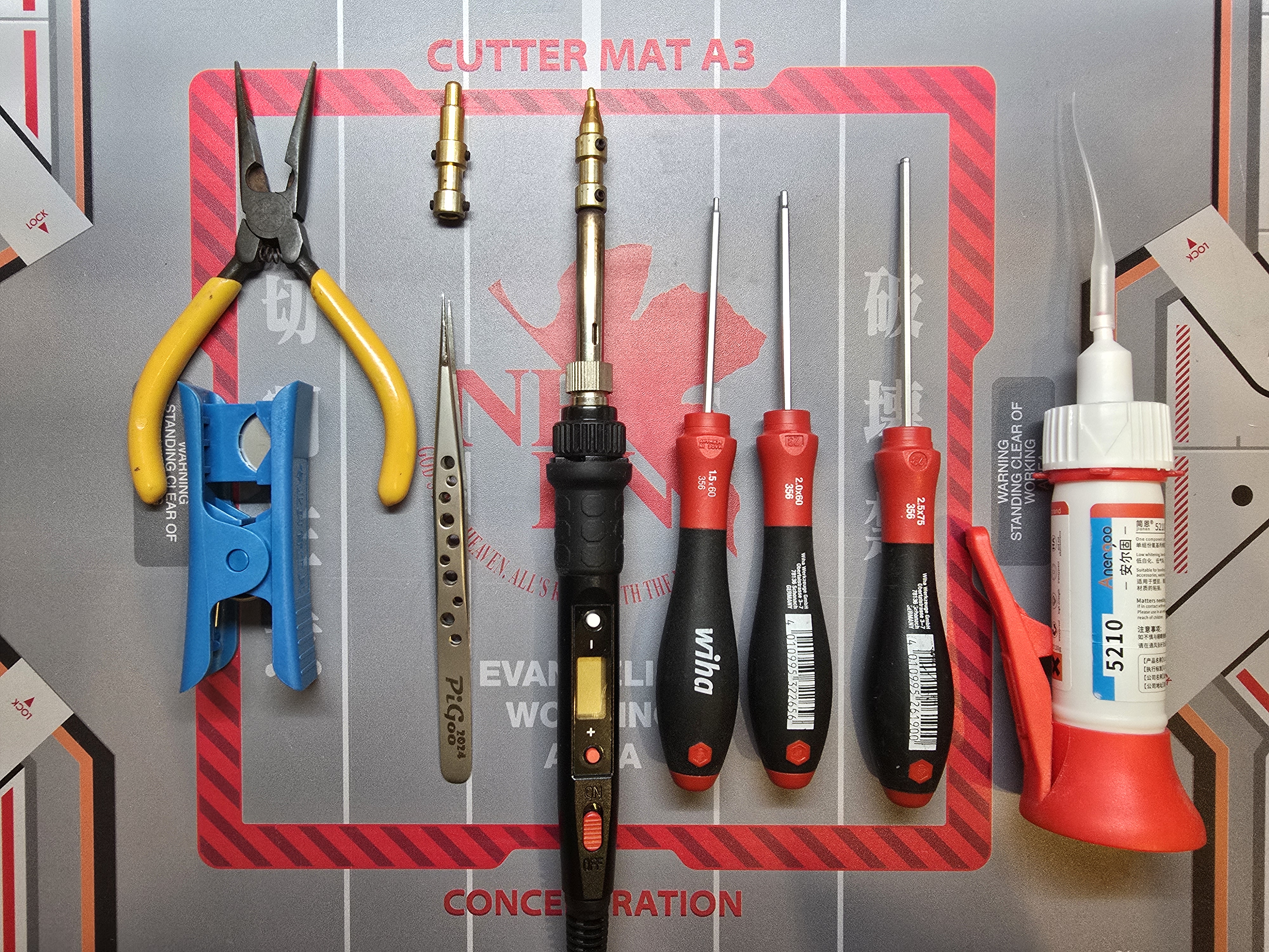
Screwdriver - Prepare corresponding tools according to the screw size required. Listed below are the tools I used:
- M1.5 Hex Driver (optional for HSSS)
- M2 Hex Driver (for Button Head Cap Screws, Flat Head Cap Screws)
- M2.5 Hex Driver (Optional, for Socket Head Cap Screws)
Soldering Iron - Reference [https://amzn.to/4igfg73](https://amzn.to/4igfg73)
Soldering Iron Tip - Heat Set Insert Press Heat Insert Tool for M3/M6
- Soldering Tip: [https://amzn.to/4crBvFC](https://amzn.to/4crBvFC)
- Other Soldering Tips: [https://amzn.to/3EhpoOY](https://amzn.to/3EhpoOY)
Tweezers - Assist in pressing heat insert nuts
Needle-Nose Pliers - Assist in embedding magnets
PTFE Tube Cutter - Any tool that can cut PTFE tubes cleanly and flat
Super Glue - Any adhesive that can bond plastic and metal
Assembly Instructions
Assembly Video:
[https://youtu.be/xXAwbM26wlg](https://youtu.be/xXAwbM26wlg)
___________________________________________
Core Component Section
Here we will use the basic 1-in-2-out nozzle switch module as an example,
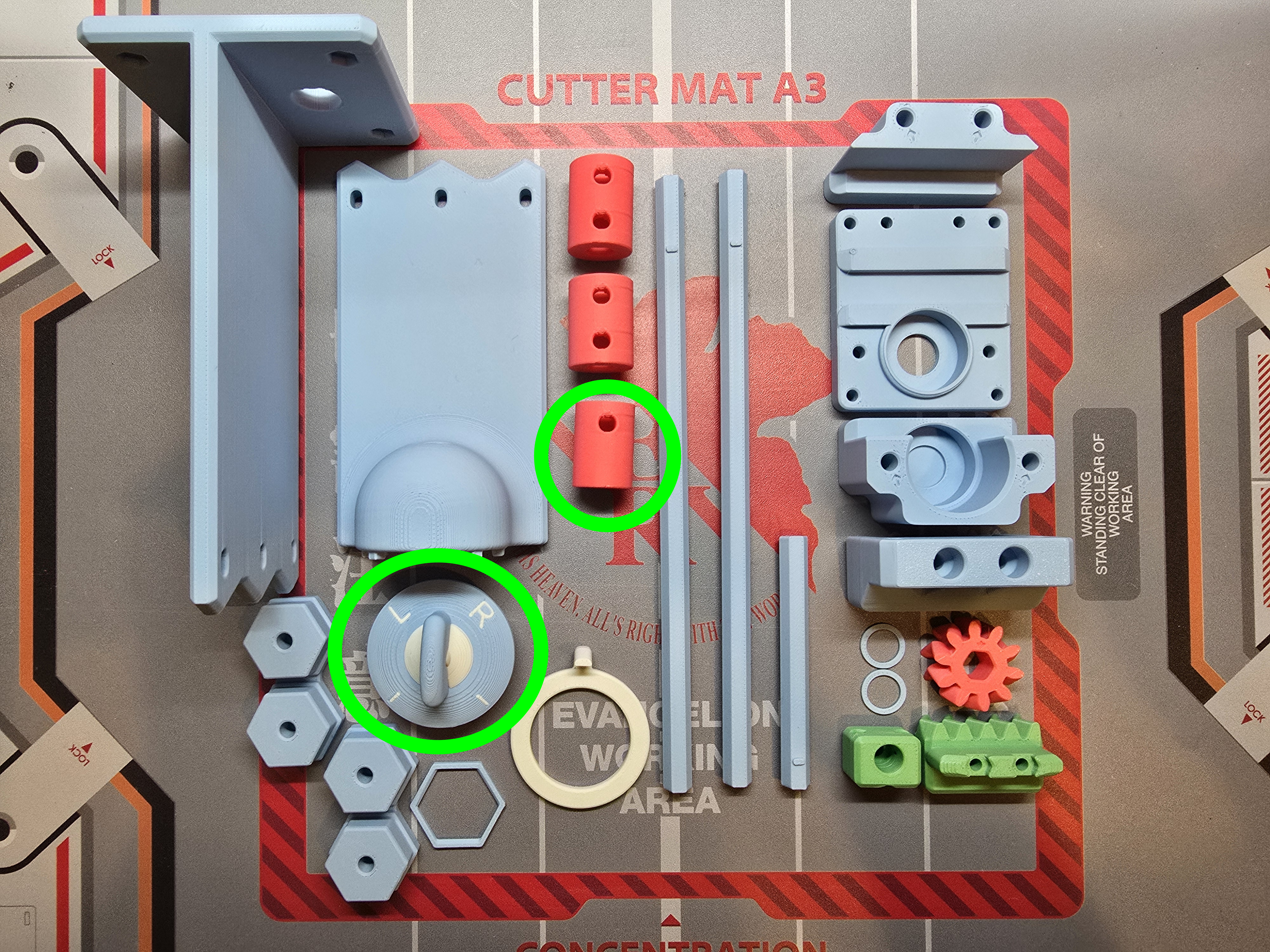
Prepare the 3D printed parts:
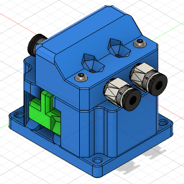
- AMS Nozzle Switch Unit
- 1-in-2-out Nozzle Switch Module
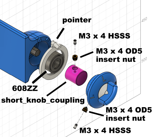
Assemble the Base:
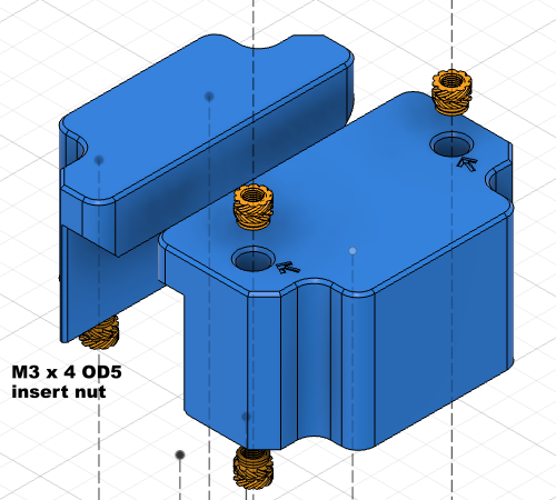
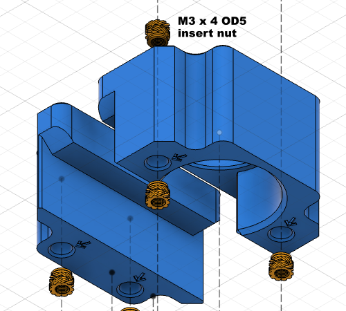
Insert M3 heat insert nuts according to the image. You can observe that the holes with arrows are the positions where they need to be inserted
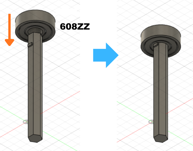
Insert the 608 bearing into the shaft rod with the stopper block
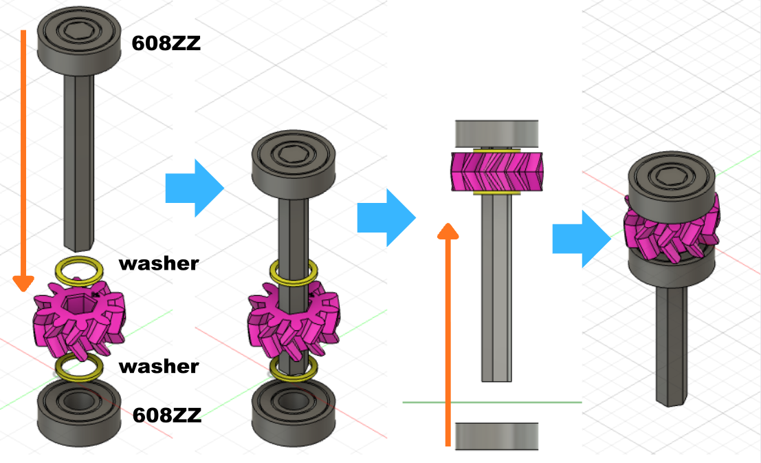
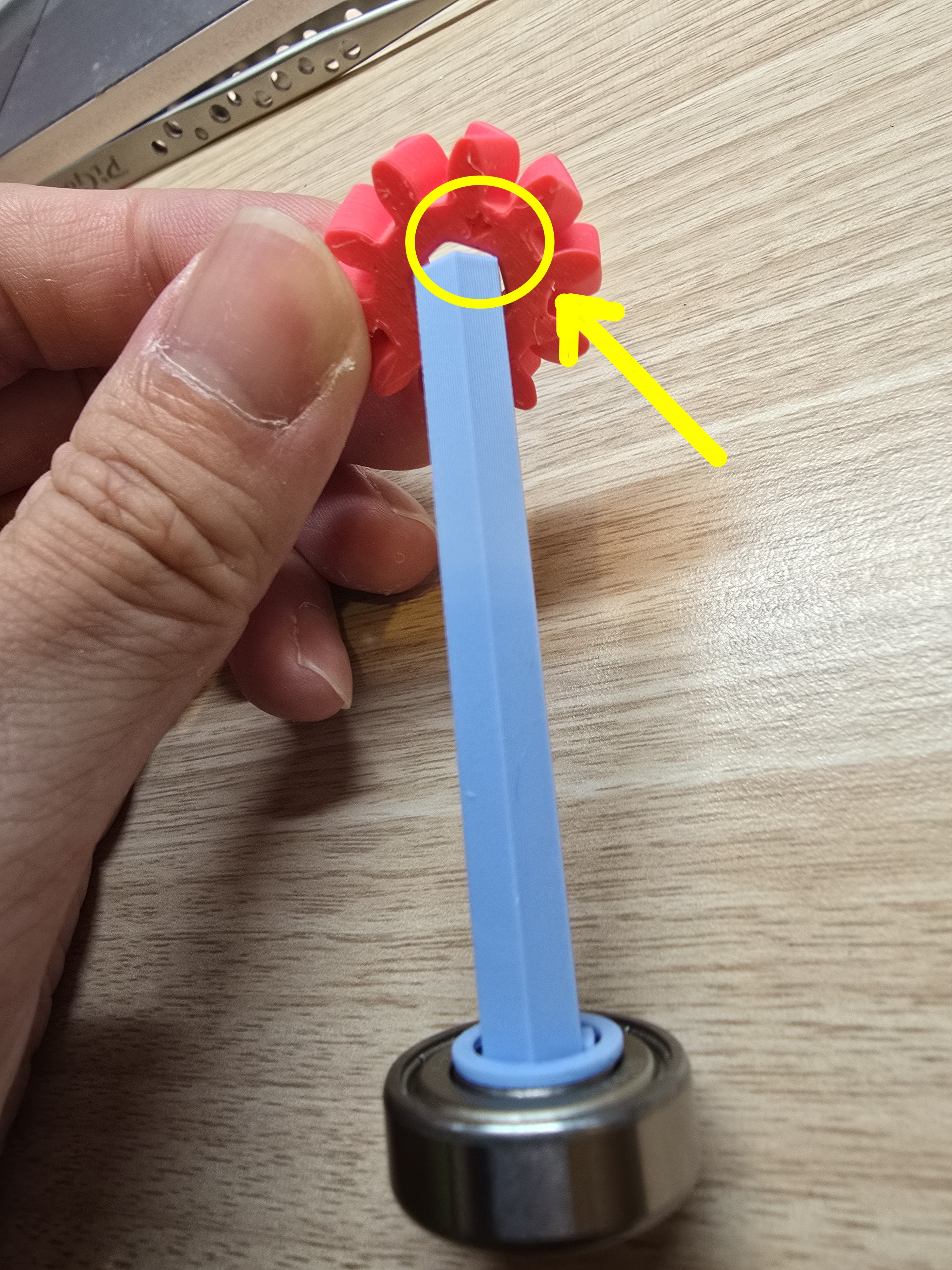
Place the washer on the other end of the shaft rod, then insert the shaft rod into the gear shaft hole with the arrow and push it all the way in
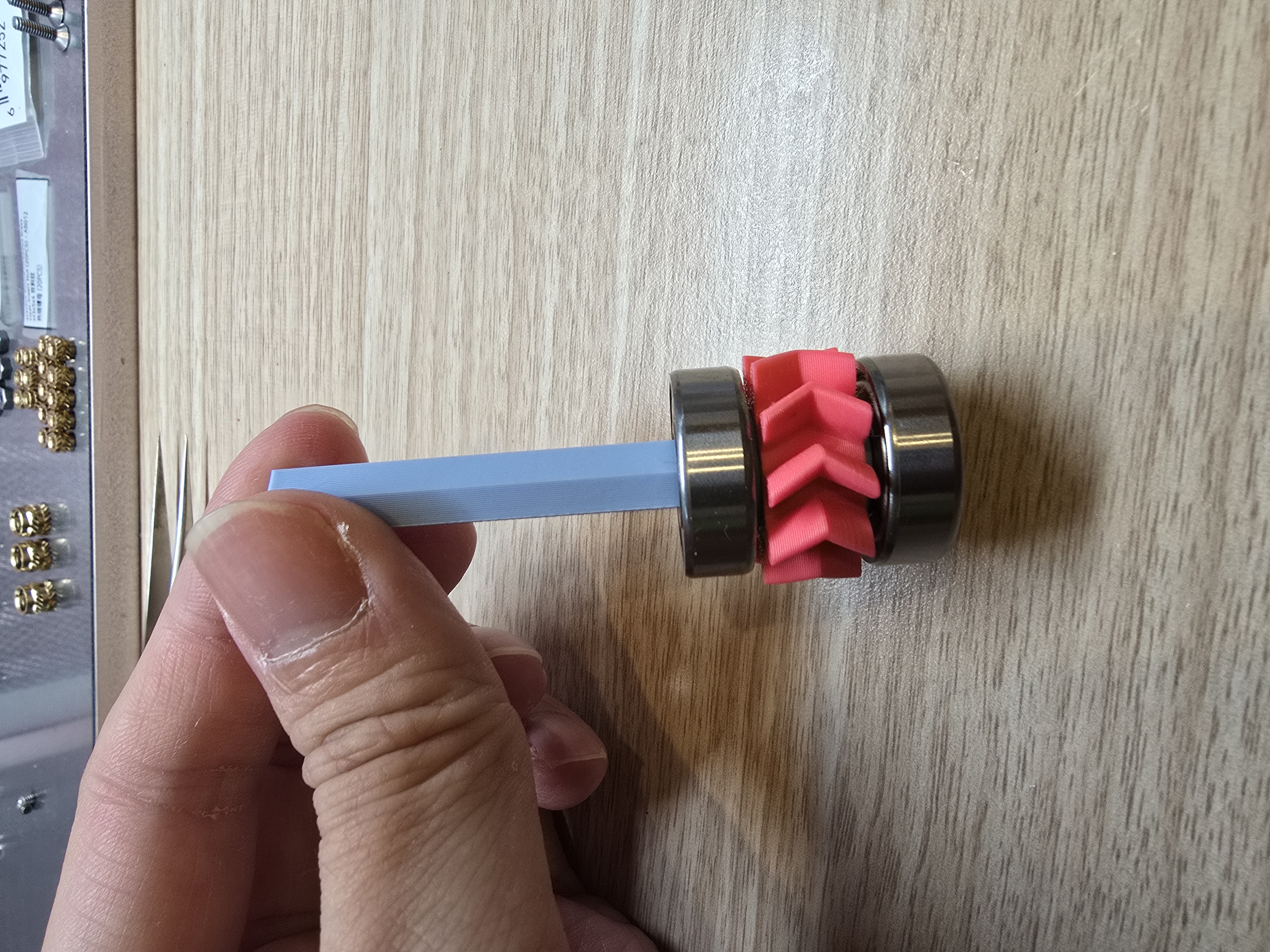
After placing another washer, insert a 608 bearing and push it all the way in
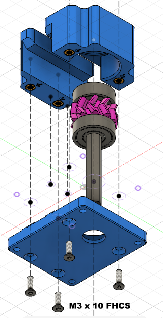
Place the assembled gear bearing into the base and secure it with 2 flat head screws
Use 2 flat head screws to secure the other part to the base
Assemble the Rack:
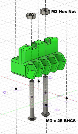
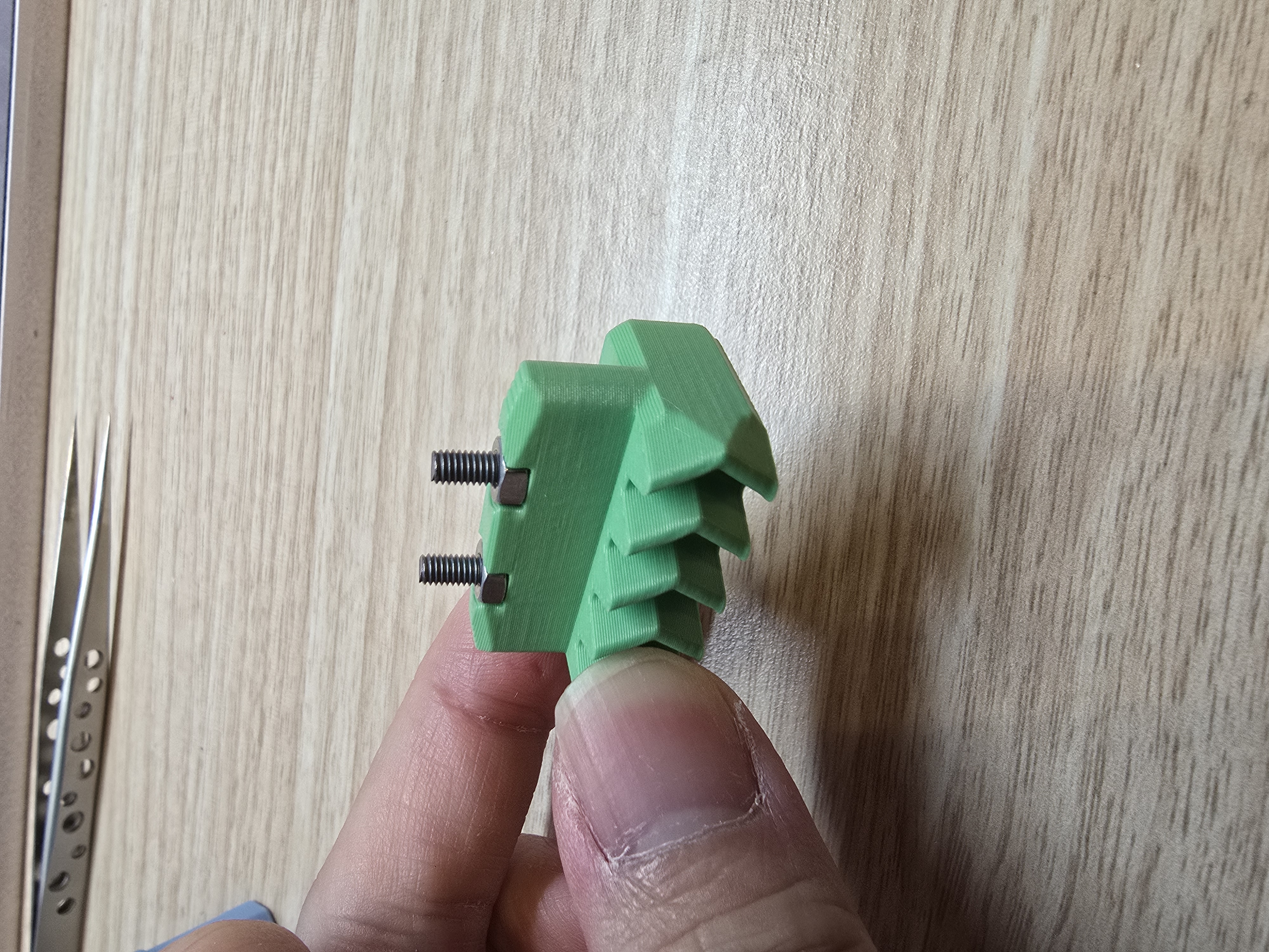
Place the M3 nut in the upper groove of the printed part
Screw in 2 button head screws from the bottom
Assemble the Nozzle Switch Module:
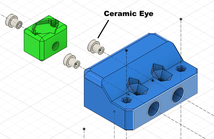
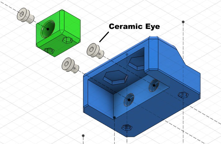
Use super glue to fix the ceramic eye to the part as shown in the image
You can use a 1.5mm hex screwdriver to assist here
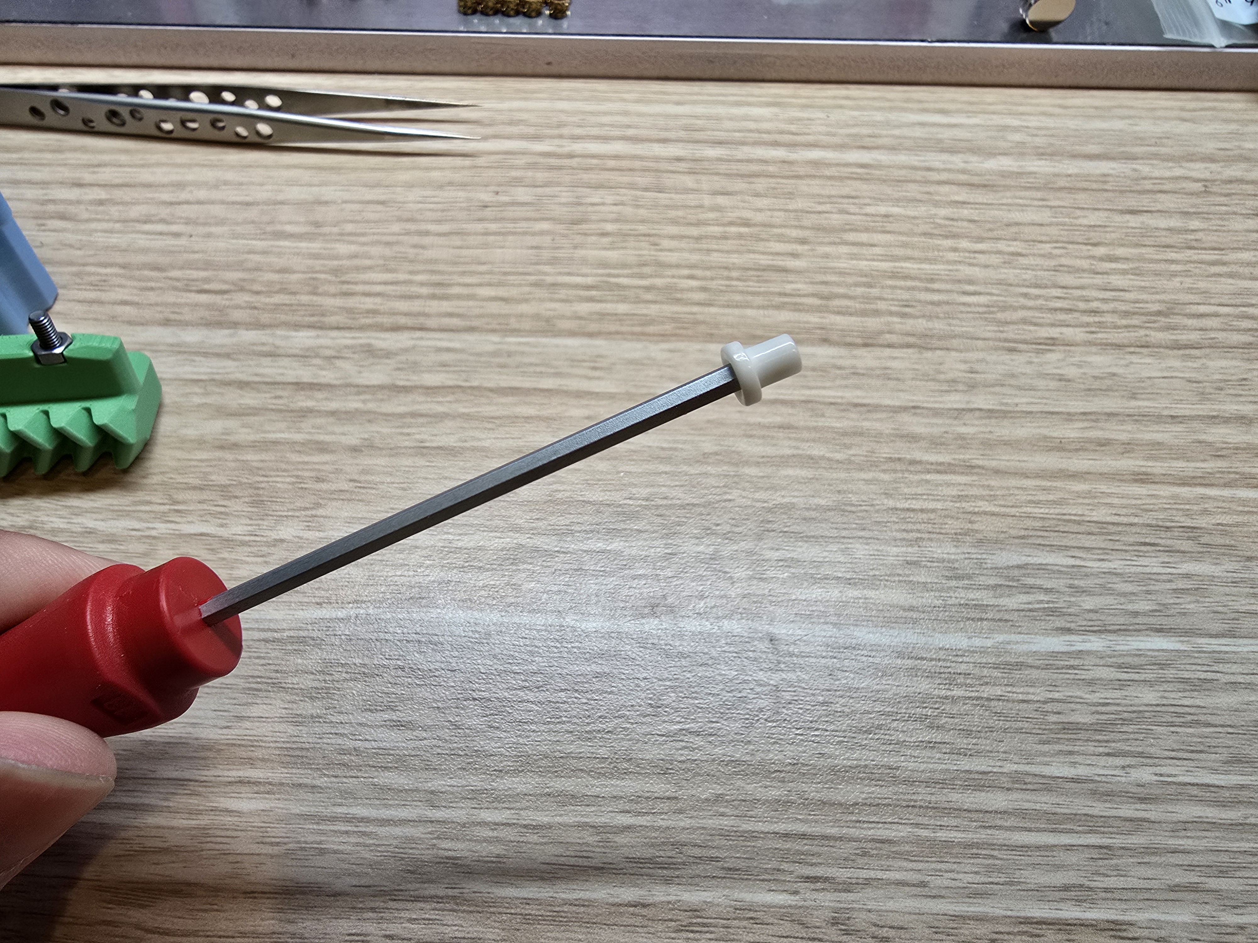
Place the ceramic eye on the front end of the hex screwdriver, apply a little super glue around it,
Push the ceramic eye in until it's flush
The other part requires inserting the ceramic eye from the inside. It's normal for part of it to protrude after insertion
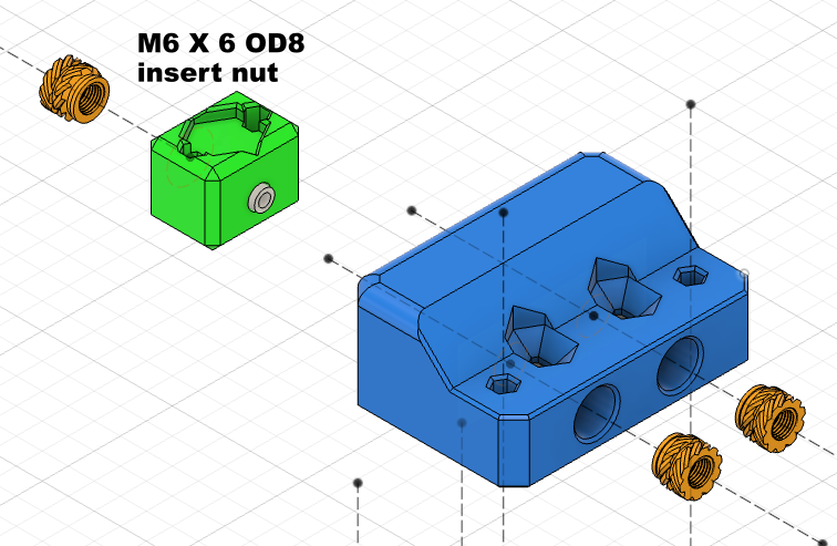
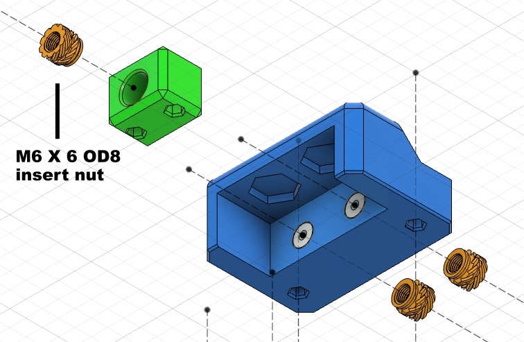
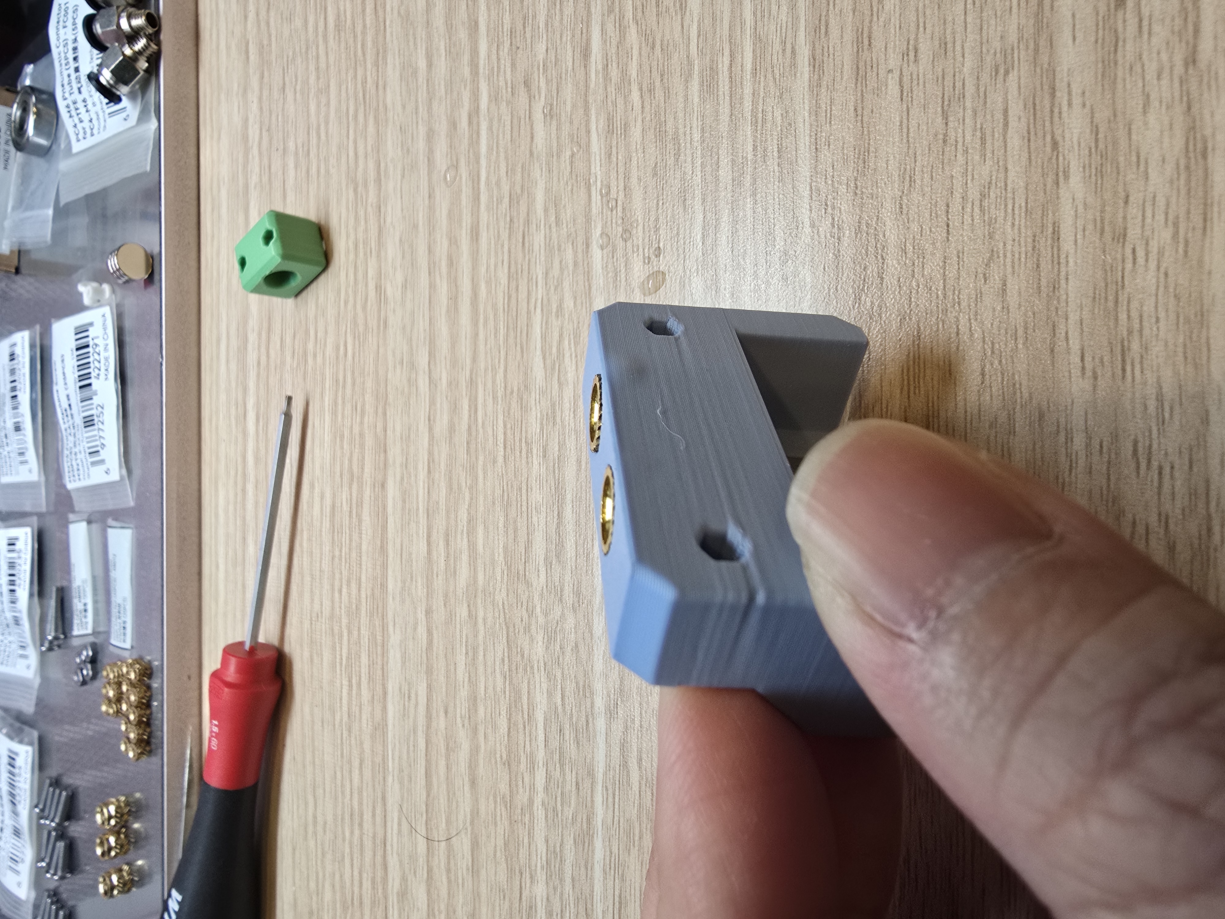
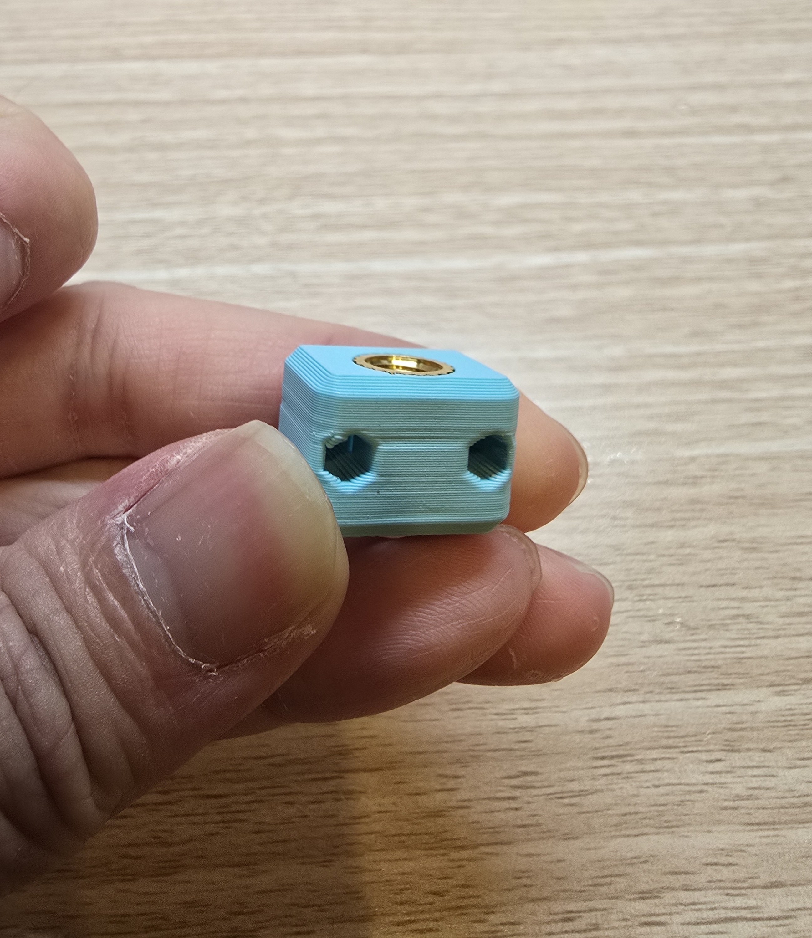
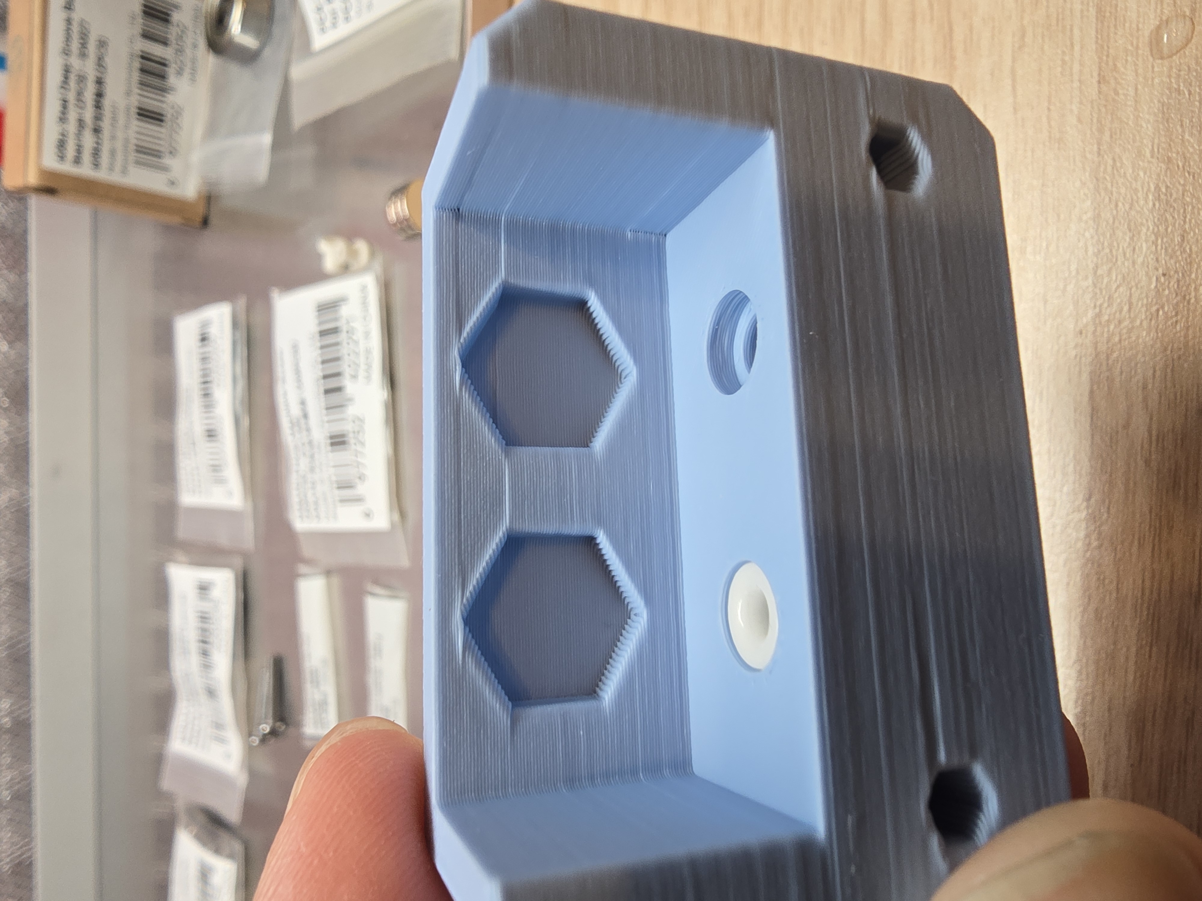
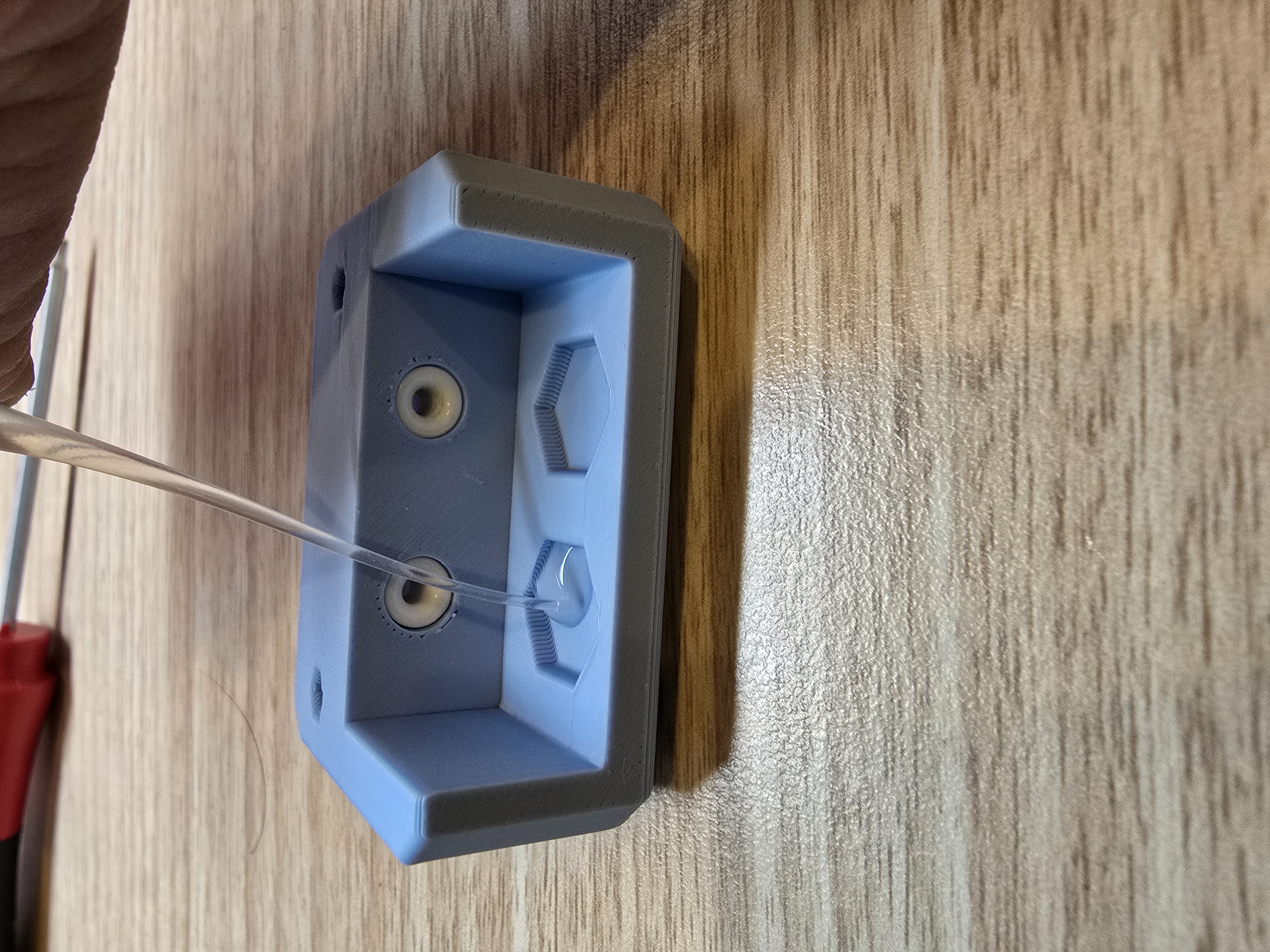
After the super glue has dried, insert M6 heat insert nuts according to the image
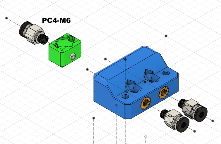
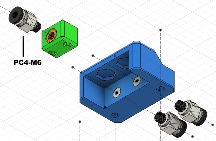
Screw 3 PC4-M6 pneumatic connectors onto the two 3D printed parts

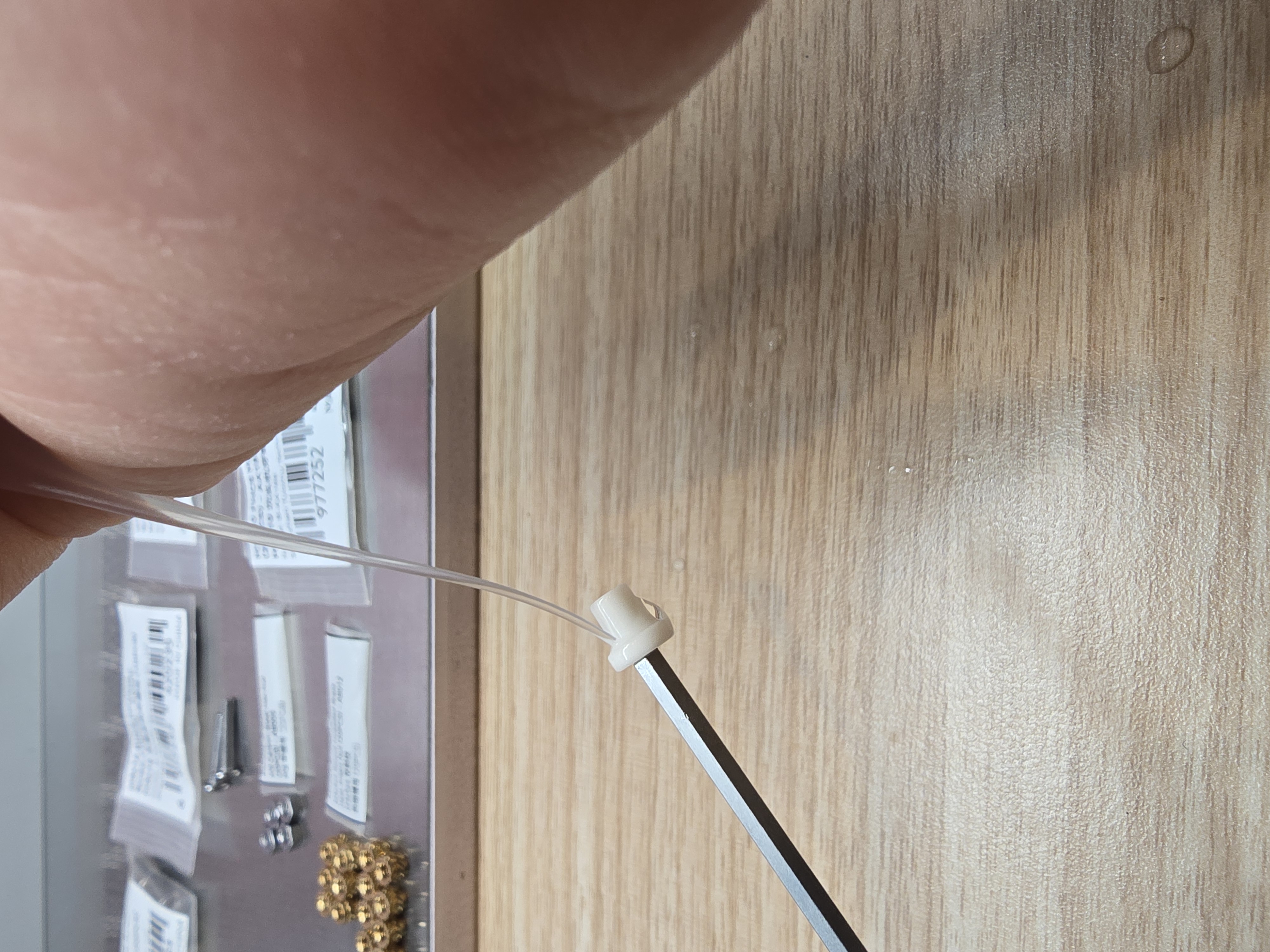
After screwing on the pneumatic connectors, this part has an observation hole. You can insert a PTFE tube to ensure it can be pushed all the way in without gaps, as shown in the image.
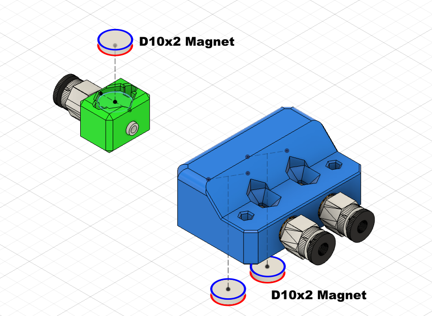
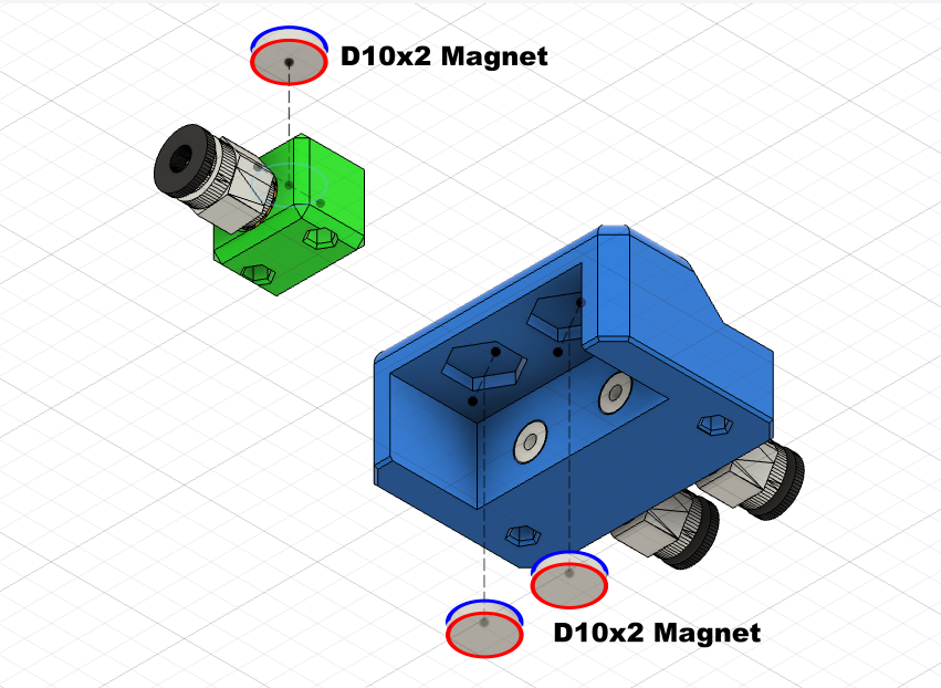
Use super glue to fix the 10x2mm magnets on the upper part of the component,
*Note: The magnetic poles of the magnets must maintain the same direction
You can use some tools to assist, and smooth out any excess super glue
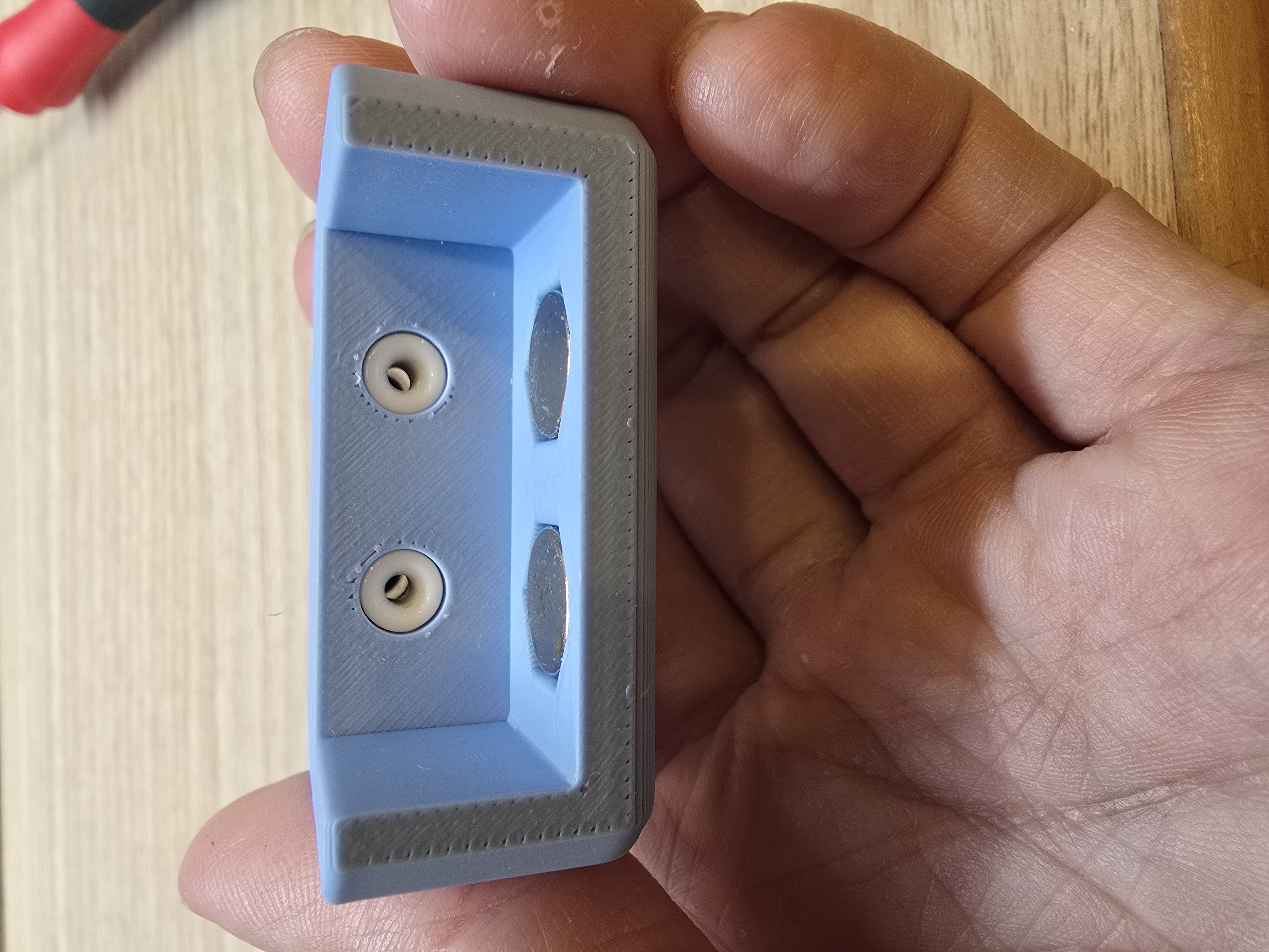
Ensure the magnet is flush with the surface after insertion.
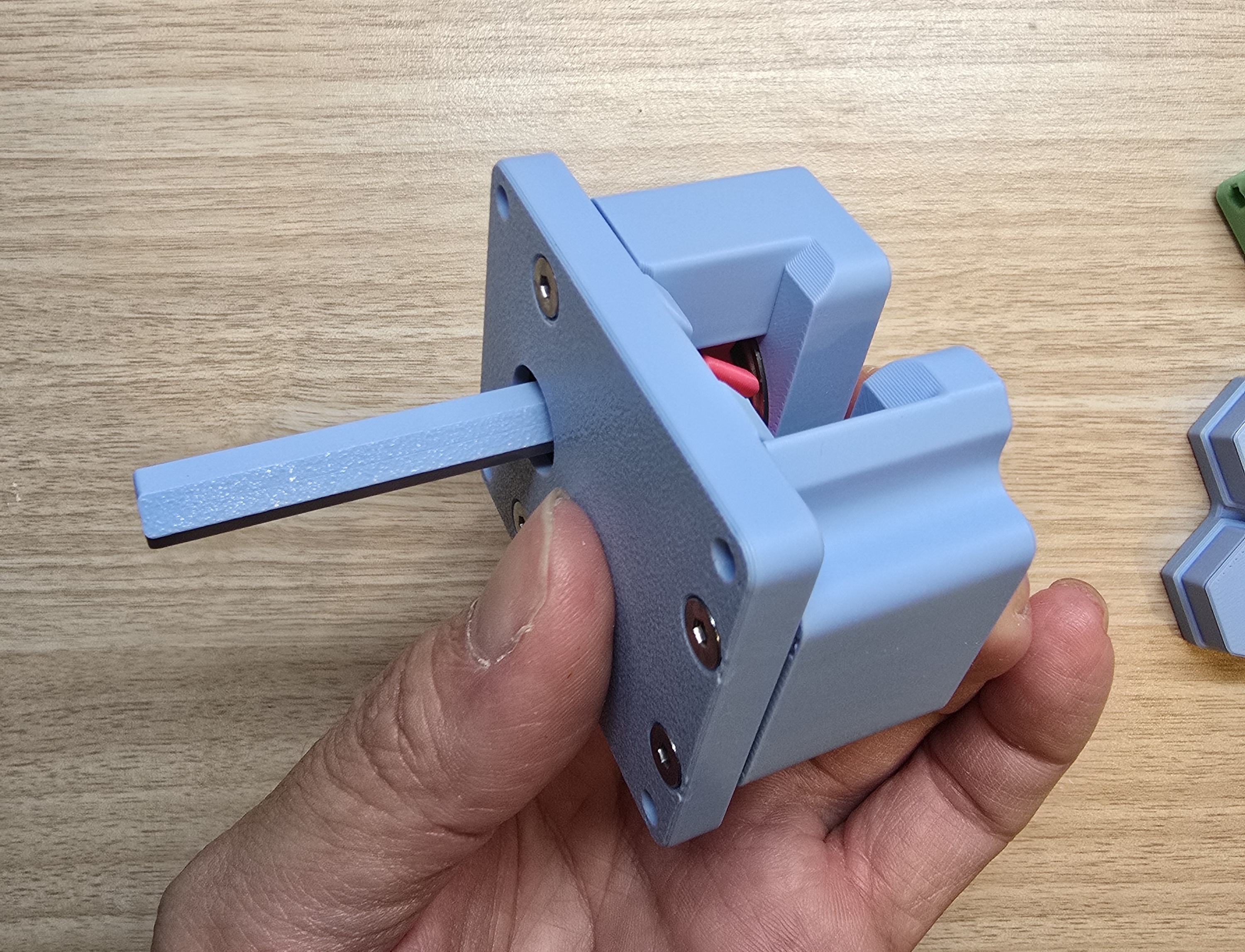
Assemble to the Base:
Push the assembled rack into the base from the side. The gears should mesh properly, otherwise it cannot be pushed in,
*If it cannot be pushed in, please disassemble the base, reverse the gear, and then reassemble it
Place the rack against the right side.
Attach the two 3D printed parts with magnets to each other, align the smaller printed part to the right
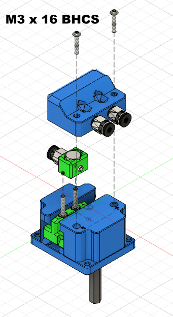
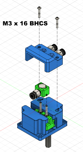
Align the switch module with the rack screws, then combine it with the base from above
And secure it with 2 M3x16 button head screws
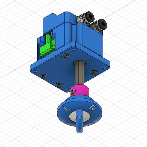
Direct Knob Assembly (Optional):
If you are using the AMS Stacking System Mount Component, please skip this section

Prepare the 3D printed parts:
- " | L R | " Knob
- Knob coupler (or shorter knob coupler)

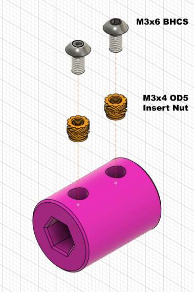
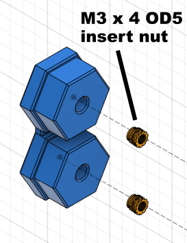
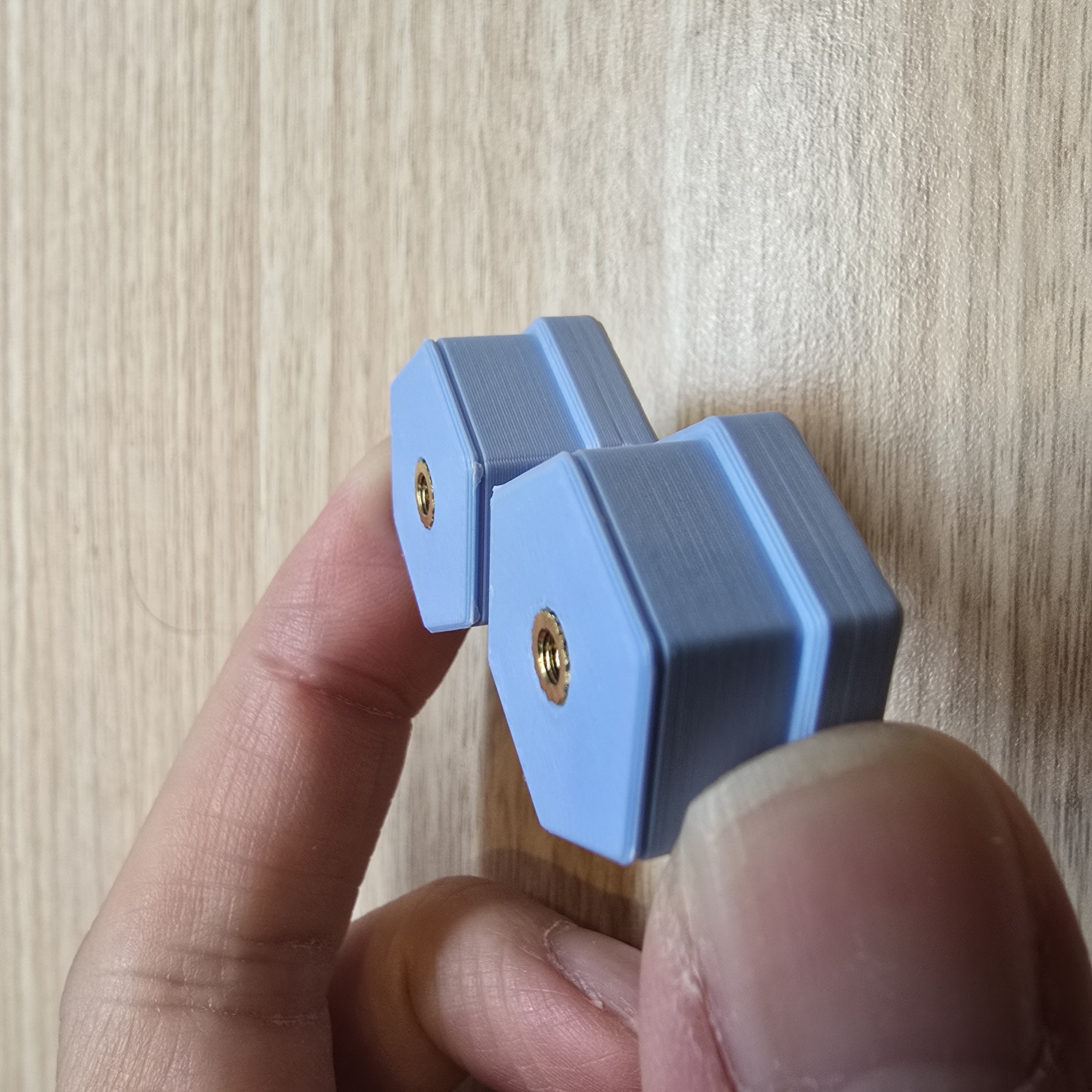
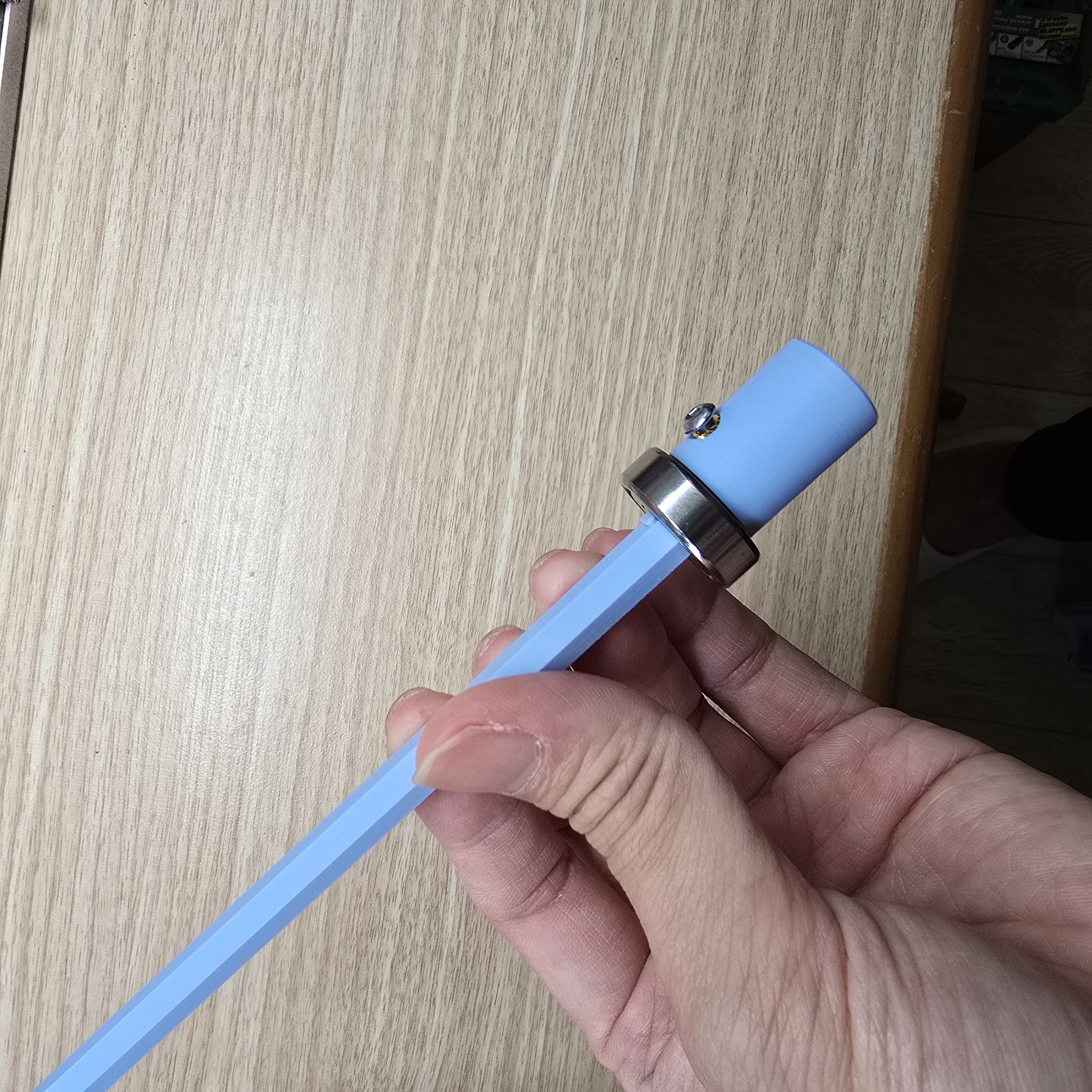
Place the knob coupler into the knob, then insert M3 heat insert nuts into the part,
This step is to prevent melted plastic from affecting the insertion of the shaft rod during embedding.
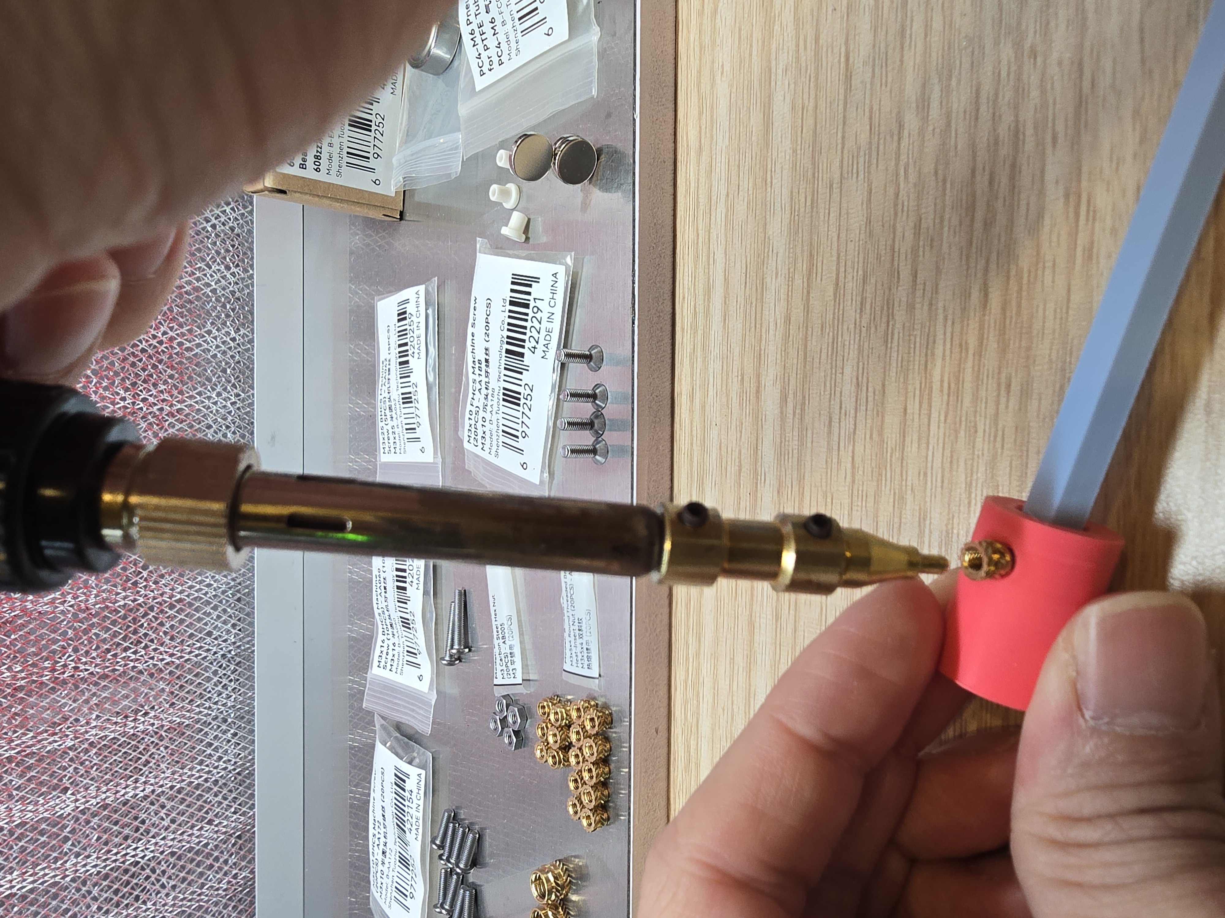
Insert the shaft rod into the knob coupler, then insert M3 heat insert nuts into the part.
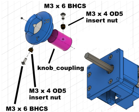
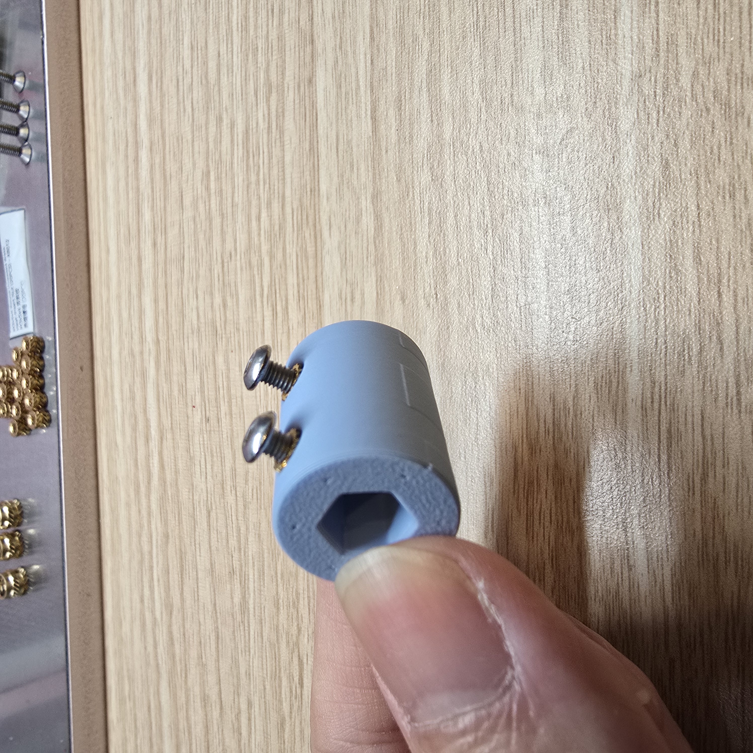
After inserting the base's shaft rod into the knob coupler, secure it with M3x6 button head screws (or M3 x 4 mm hex socket set screws (HSSS))
Then insert the knob coupler into the knob, and secure it with M3x6 button head screws (or M3 x 4 mm hex socket set screws (HSSS)) according to the desired angle
___________________________________________
AMS Stacking System Mount Component Section
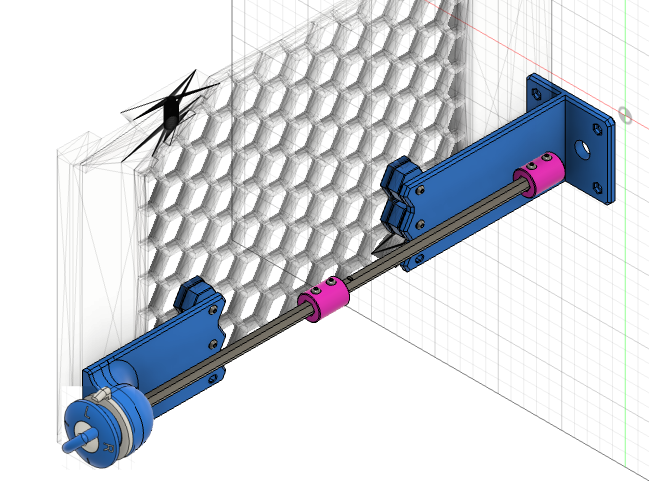
Here we use the AMS 1 & 2 Pro & HT Modular Sliding Stacking System - By Shuwn Hsu
as an assembly example,
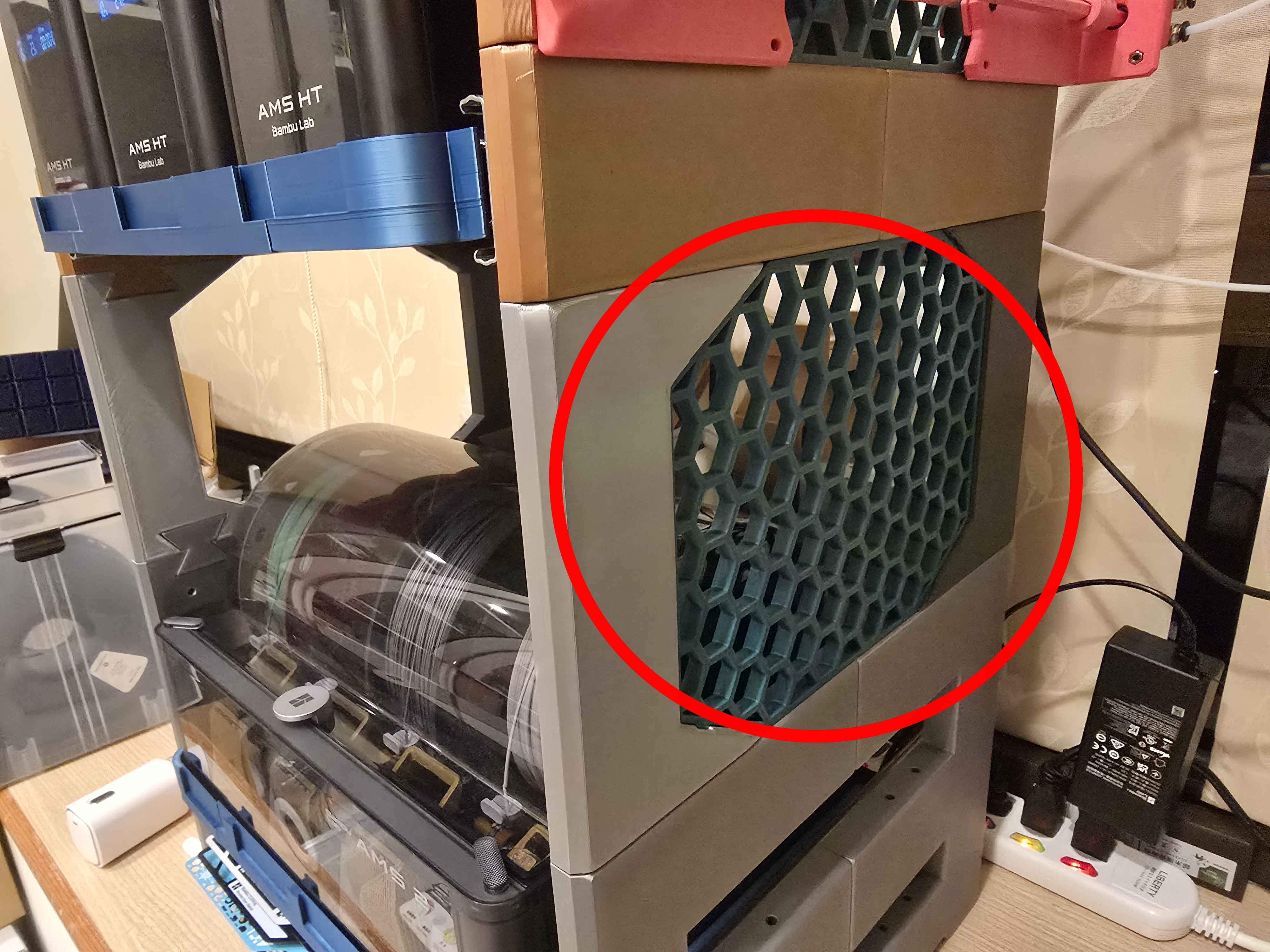
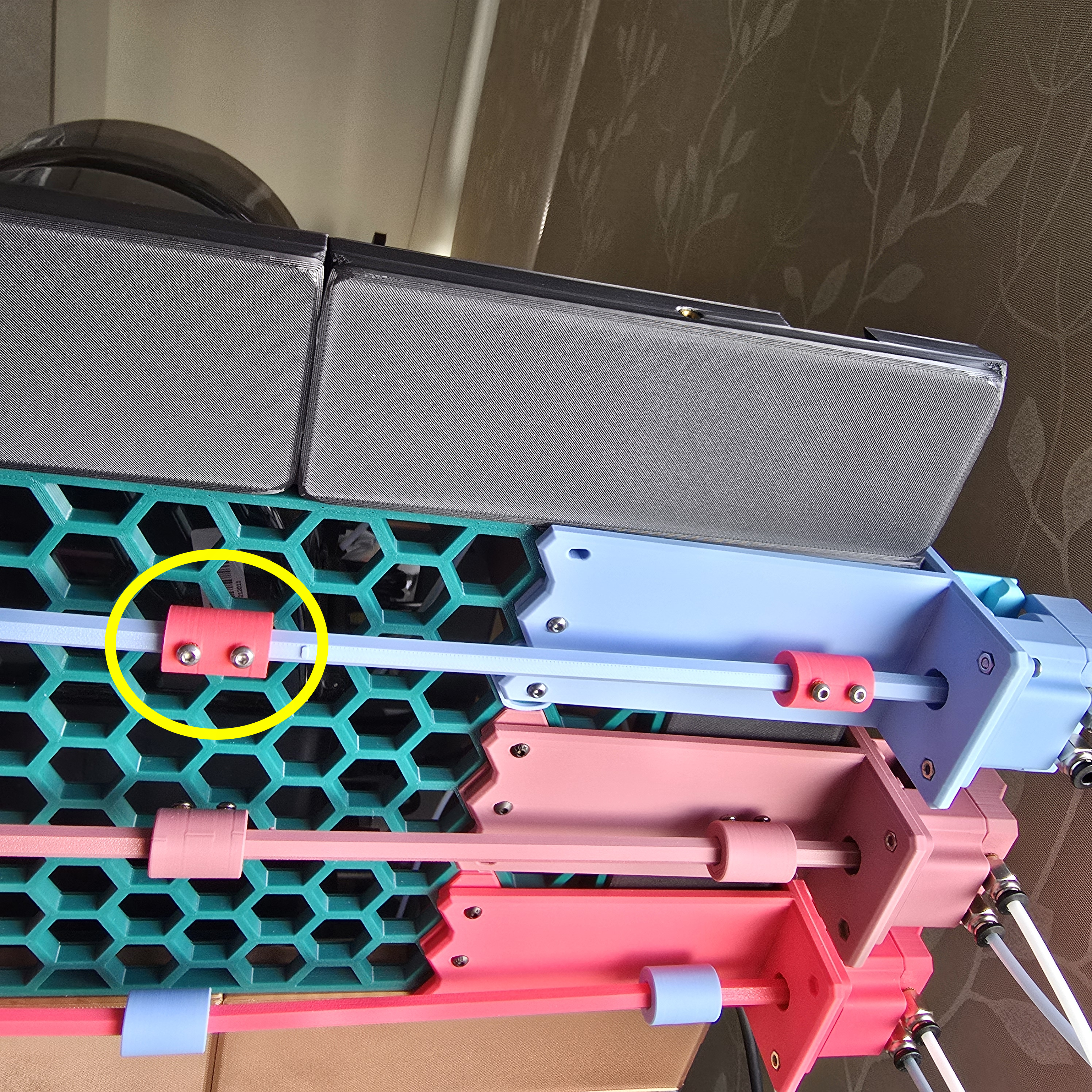
Before assembly, make sure you have installed the Honeycomb Storage Wall before you can assemble this mount.
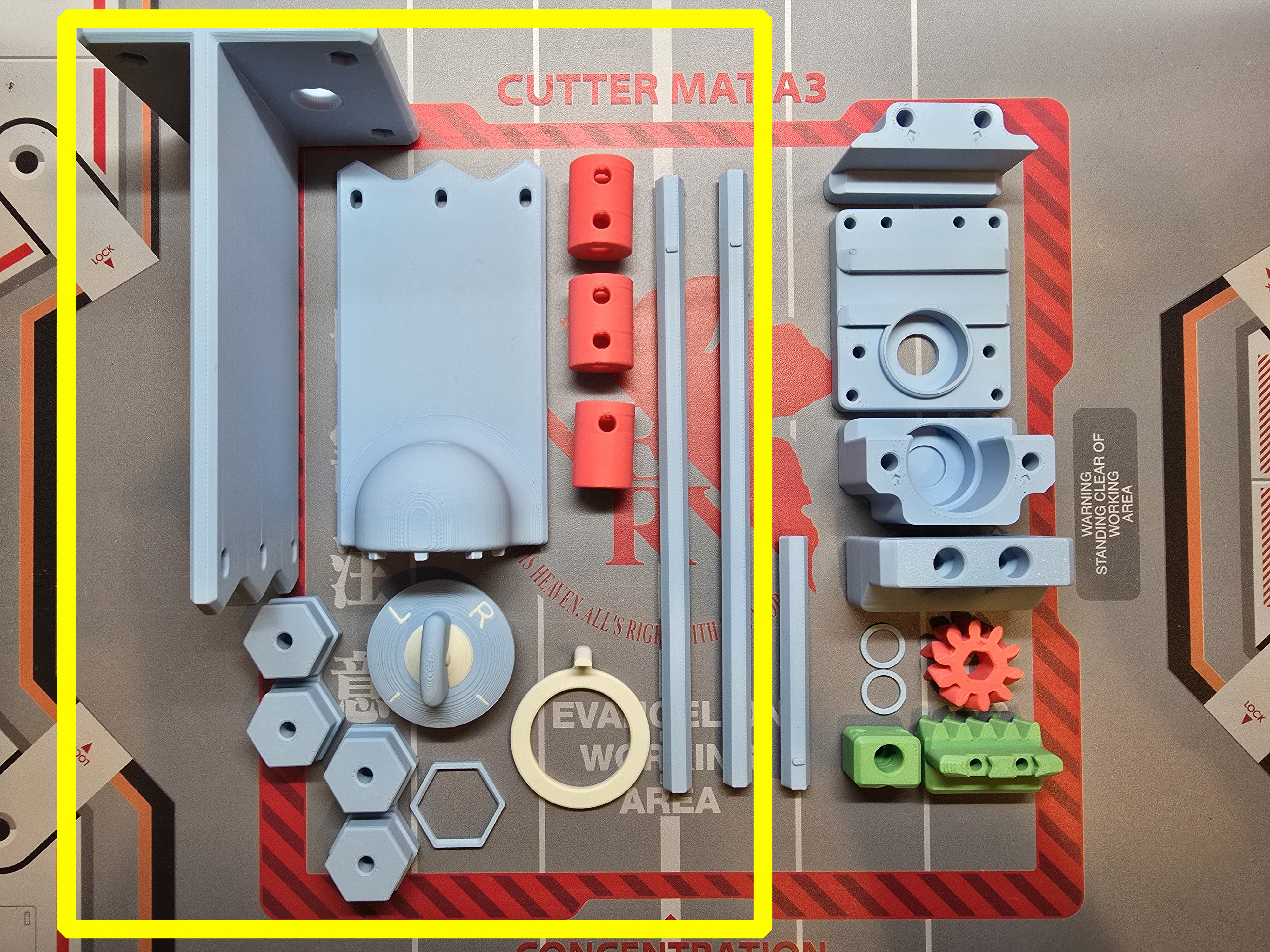
Prepare the 3D printed parts:
- Extended axis rod and mount
- Knob
- Knob coupler (or shorter knob coupler)
- Knob pointer
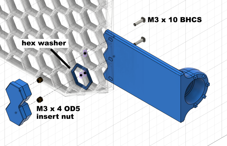
Insert the shaft rod into the coupler, then insert M3 heat insert nuts into the part.
Insert the honeycomb mount part into the M3 heat insert nuts.
Assemble the Rear Mount:
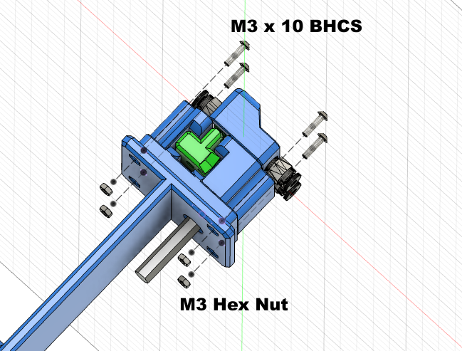
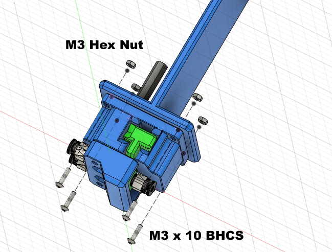
Use 4 M3 x 10 button head screws and 4 M3 nuts to secure the core component to the rear mount
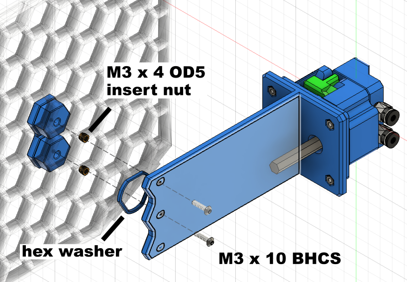
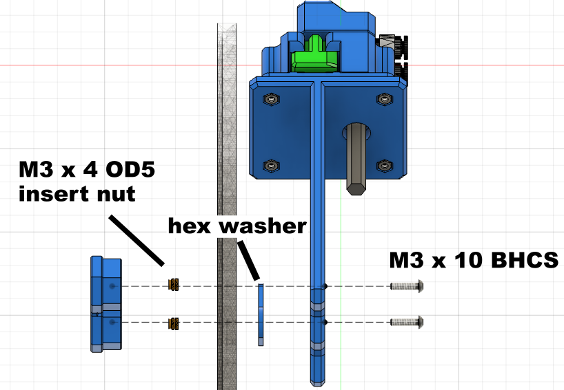
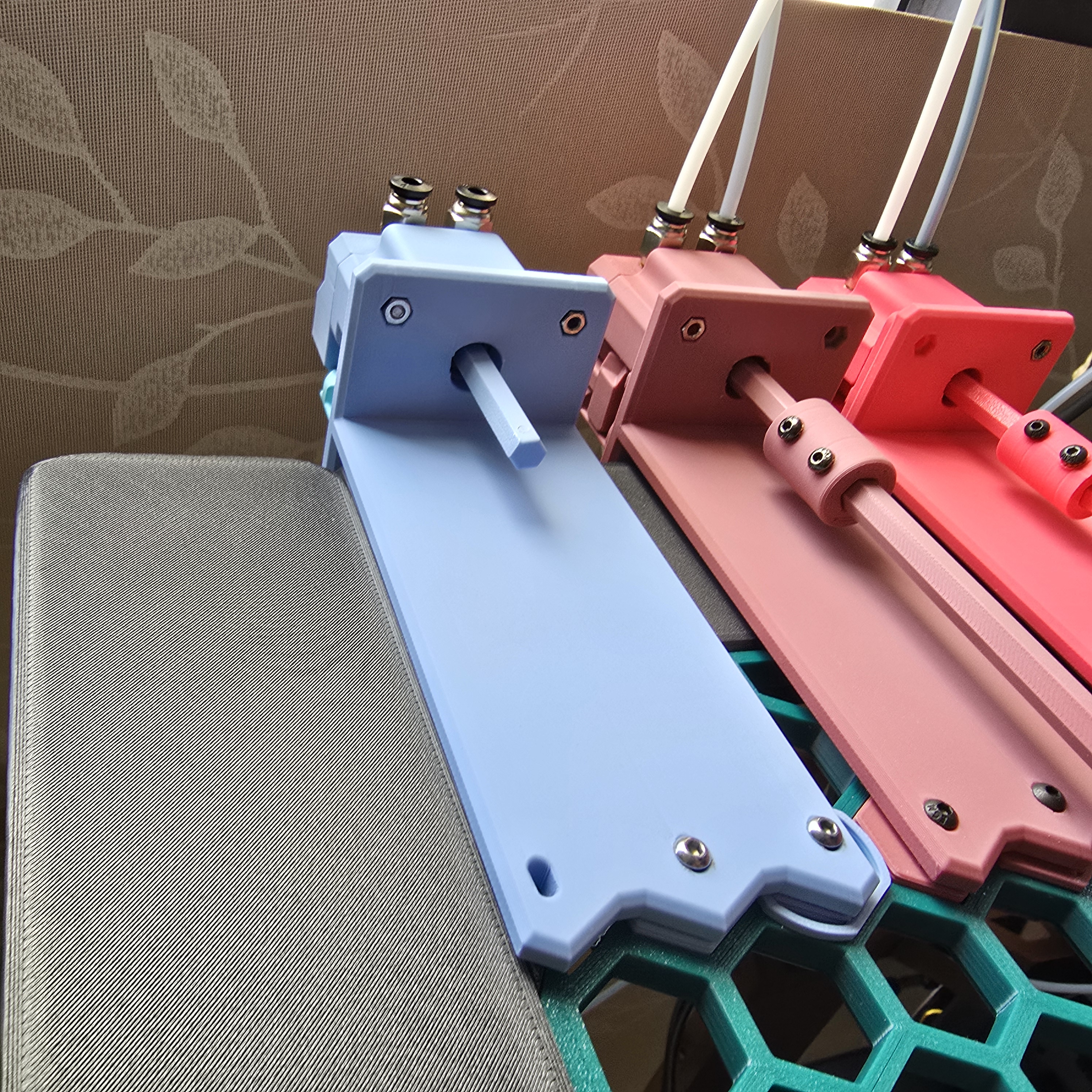
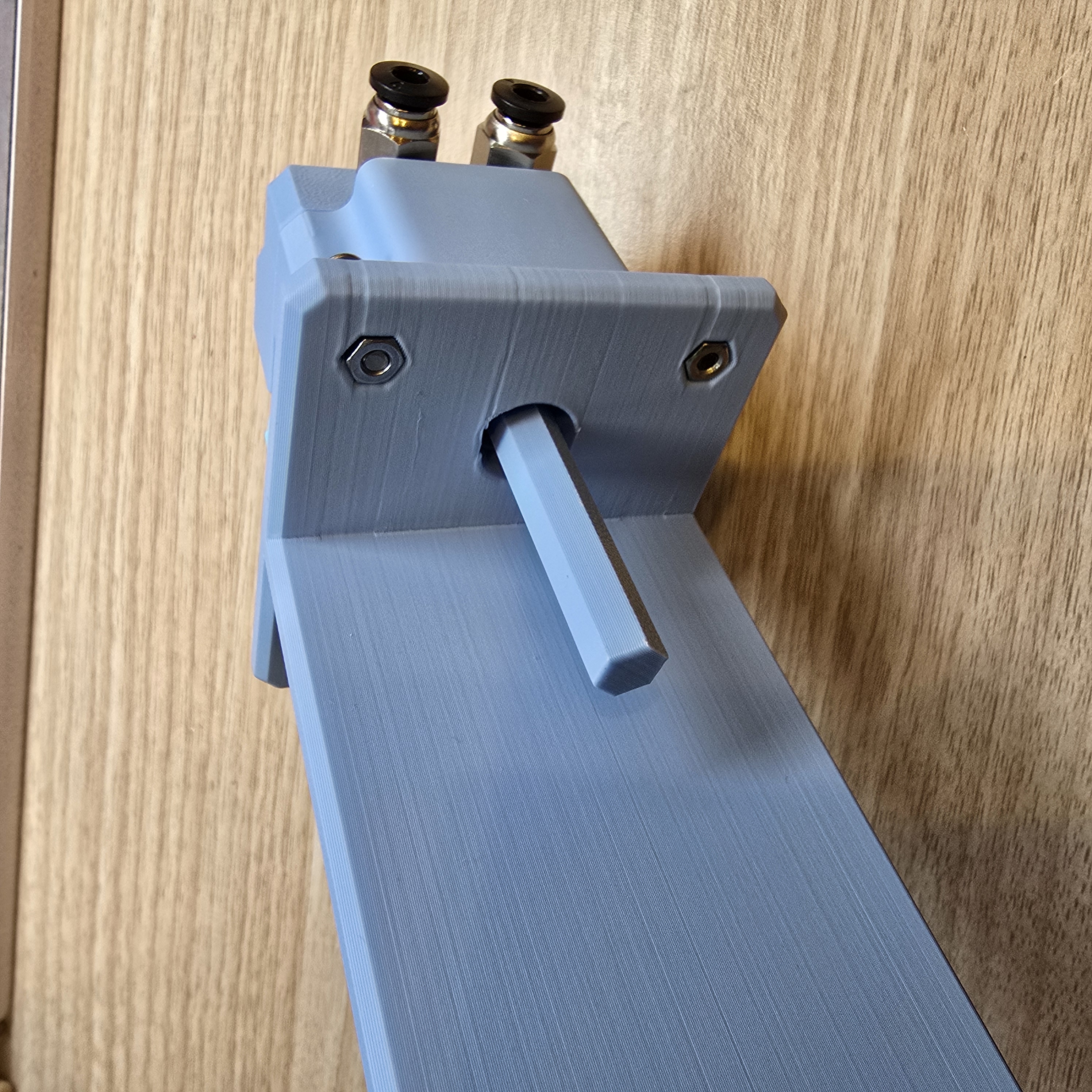
Install the mount part from the inside of the honeycomb, install the hex washer from the outside to prevent the part from falling off, then use 2 M3 x 10 button head screws to secure the rear mount to the Honeycomb Storage Wall.
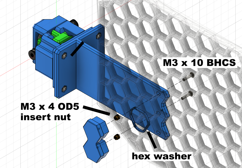
Assemble the Front Mount:
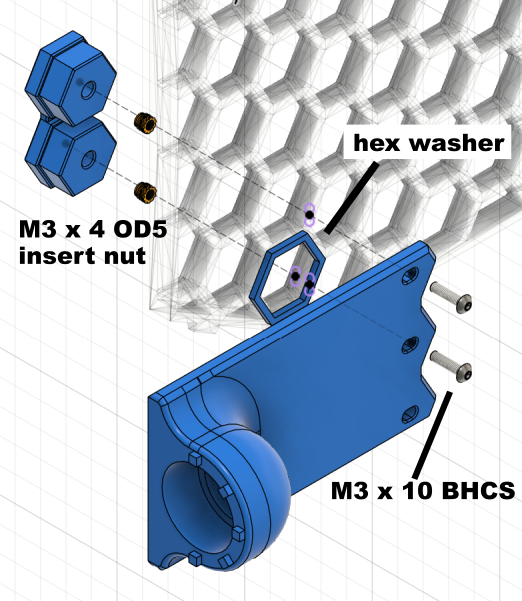
Install the mount part from the inside of the honeycomb, install the hex washer from the outside to prevent the part from falling off, then use 2 M3 x 10 button head screws to secure the front mount to the Honeycomb Storage Wall.
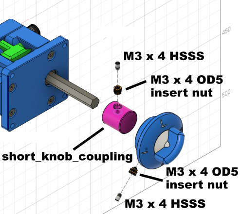
Assemble the Knob:
*(Optional) you can also use a shorter knob coupler here, as shown in the image below
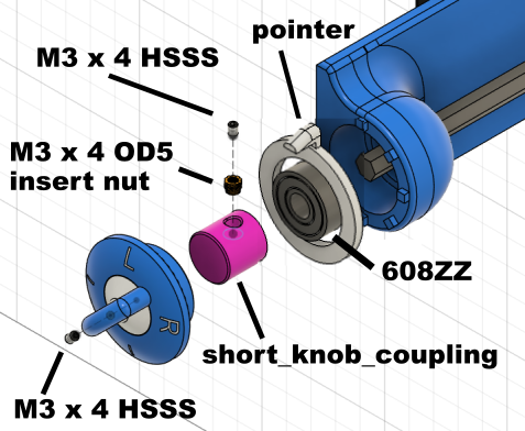
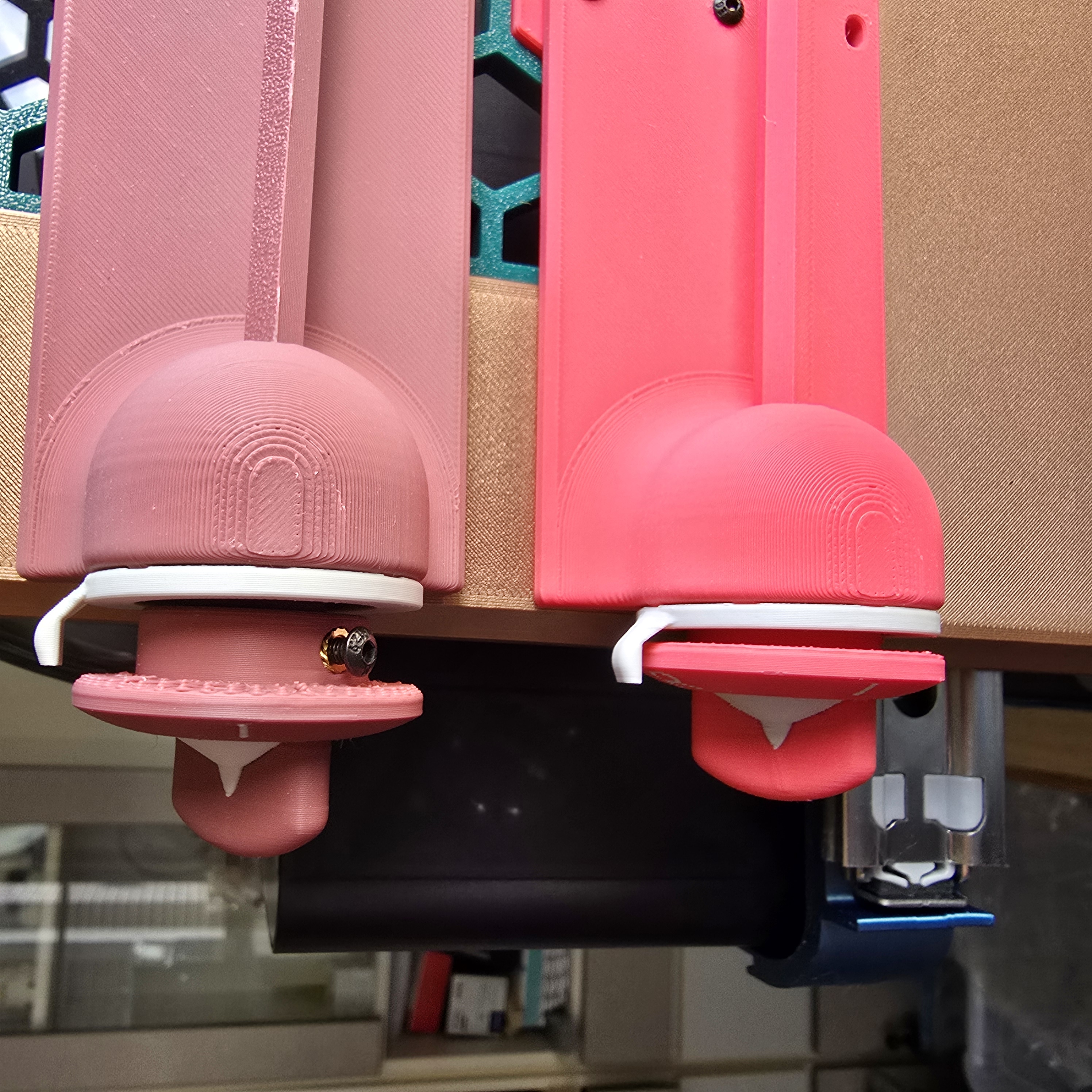
*paired with M3 x 4 mm hex socket set screws (HSSS) to achieve better assembly results for the knob
Rotate the pointer part to your desired angle, then fix it to the front mount using super glue.
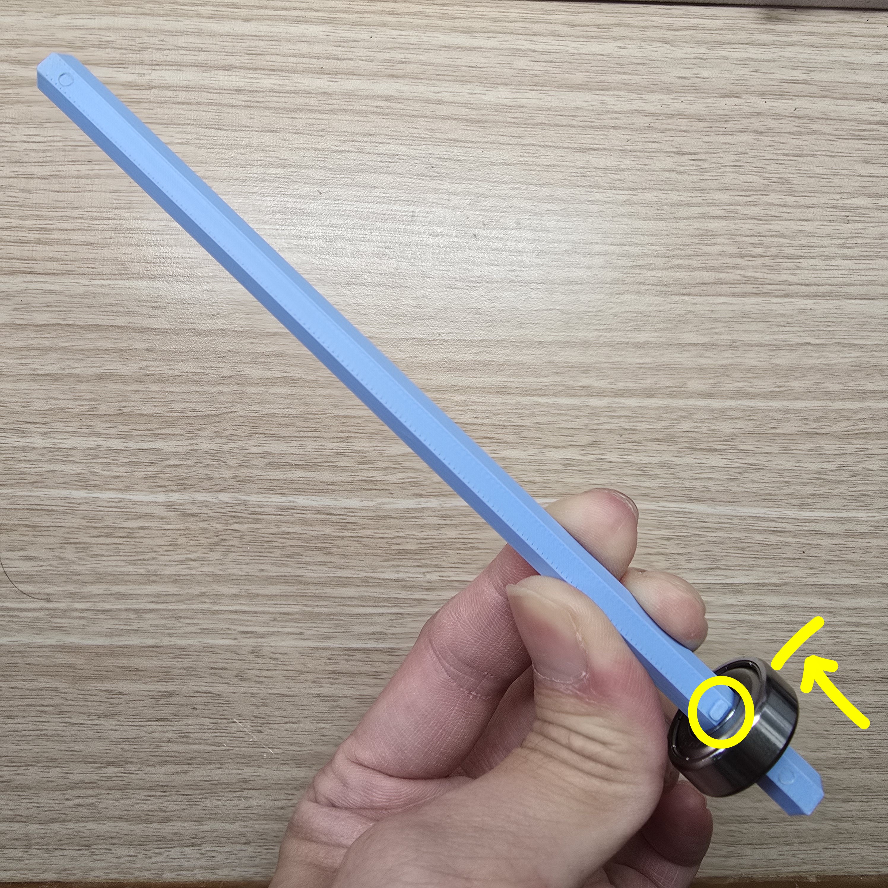
Insert the 608 bearing into the end of the 170mm shaft rod near the stopper, push it all the way in,
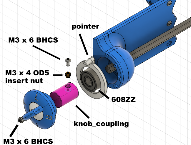
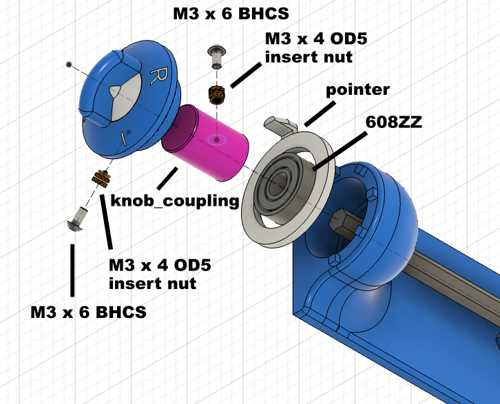
Insert the knob coupler onto the shaft rod, then secure it with M3x6 button head screws (or M3 x 4 mm hex socket set screws (HSSS)), and place it together into the front mount

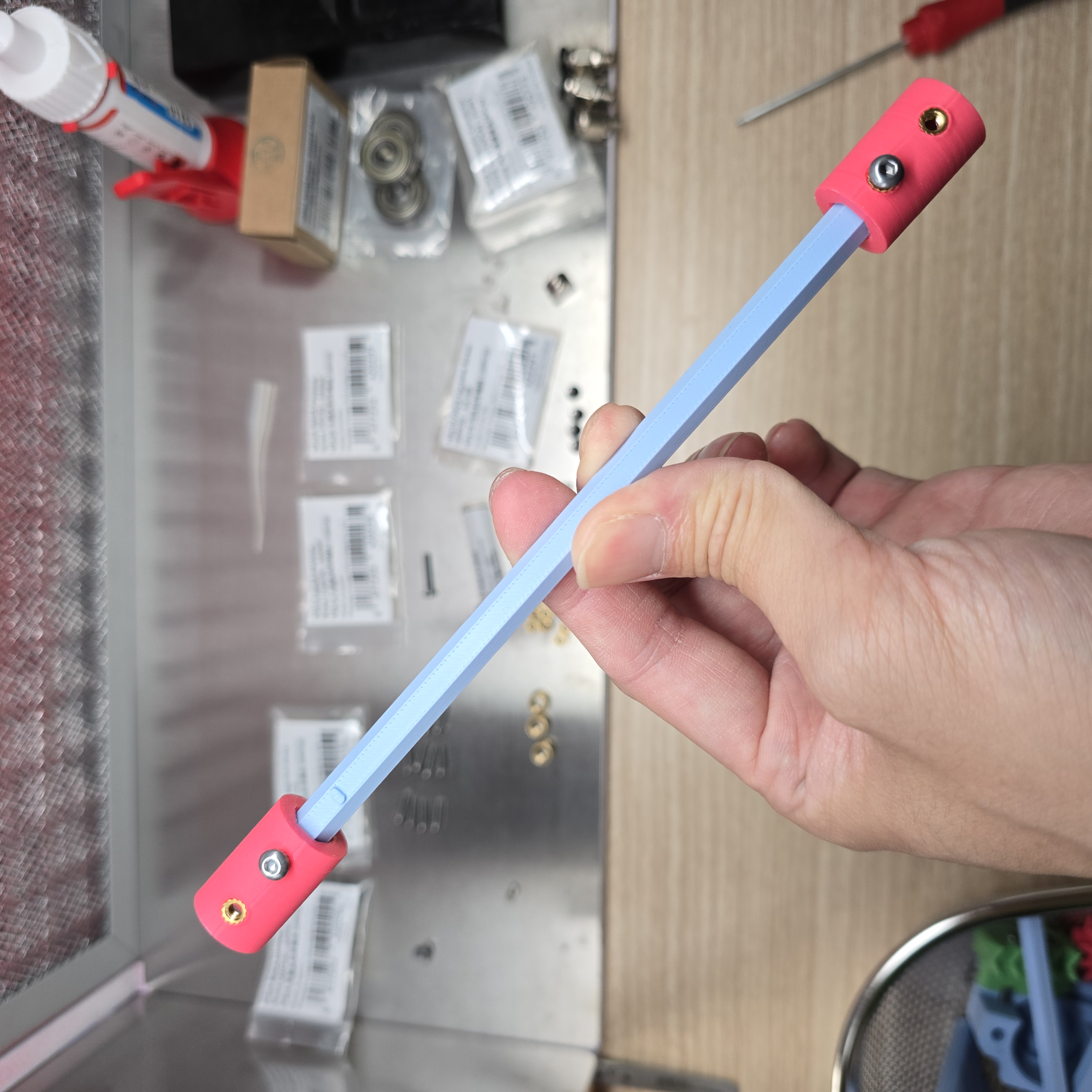
Insert one coupler into each end of another 170mm shaft rod, with the insertion depth being half the height of the coupler, then secure each with one M3x6 button head screw (or M3 x 4 mm hex socket set screw (HSSS))
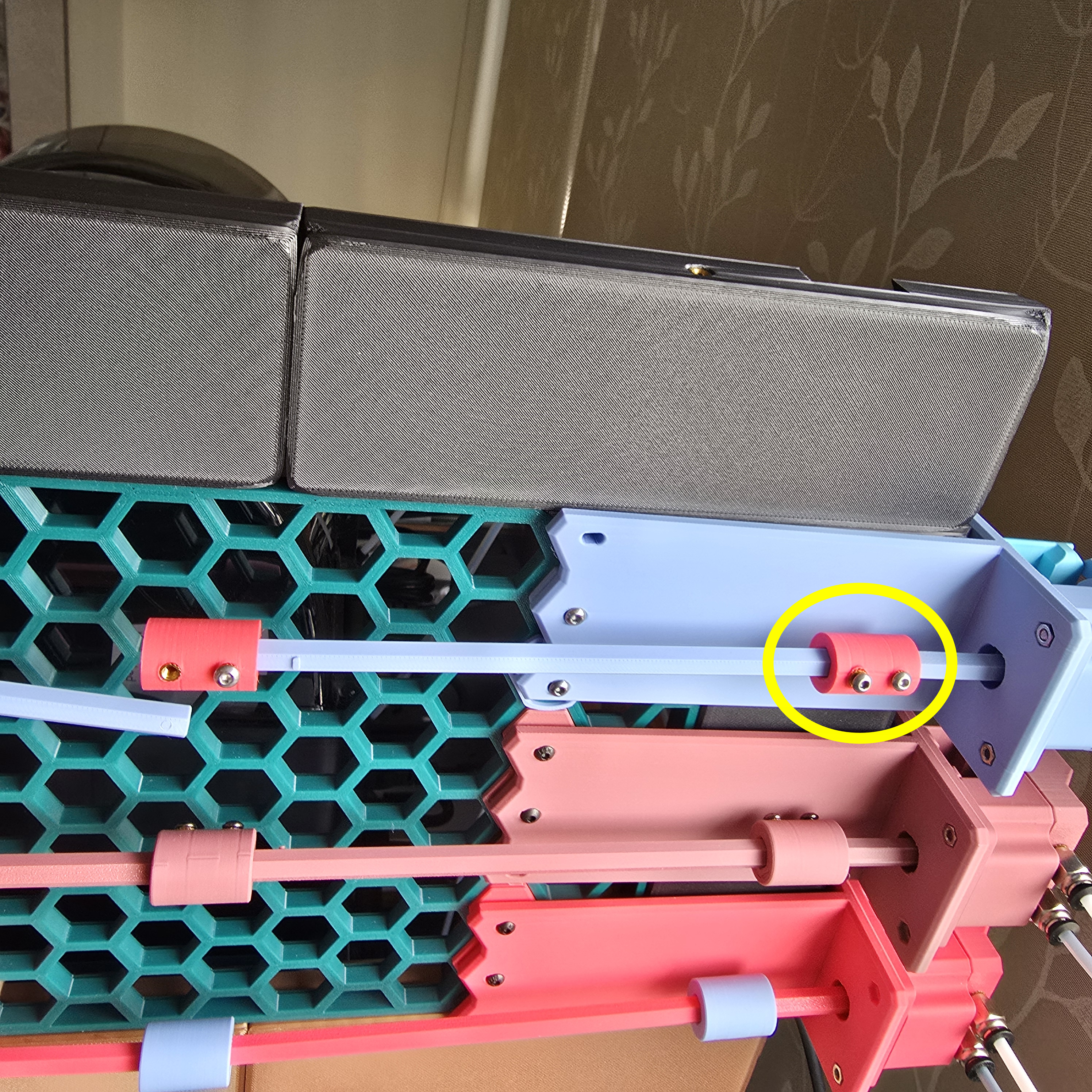
Secure it to the rear shaft rod with M3x6 button head screws (or M3 x 4 mm hex socket set screws (HSSS)),
Do not secure the front coupler yet,
Place the knob on the knob coupler
Ensure that the "L" mark on the top of the knob is aligned with the pointer part, then secure it with M3x6 button head screws (or M3 x 4 mm hex socket set screws (HSSS)).
After securing the knob, secure the front coupler that was left unfixed earlier to complete the assembly.
___________________________________________
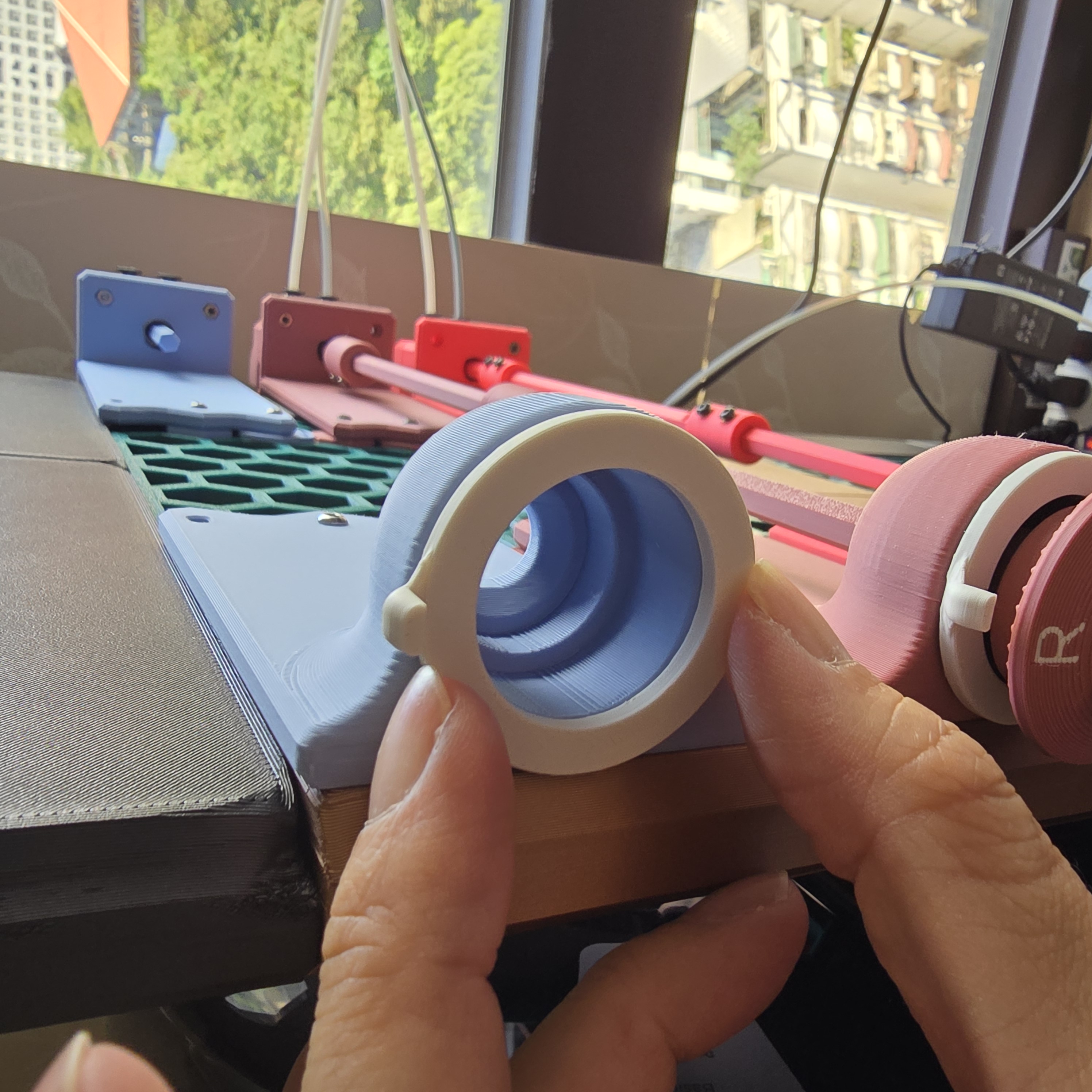
Connecting AMS Nozzle Switch Unit
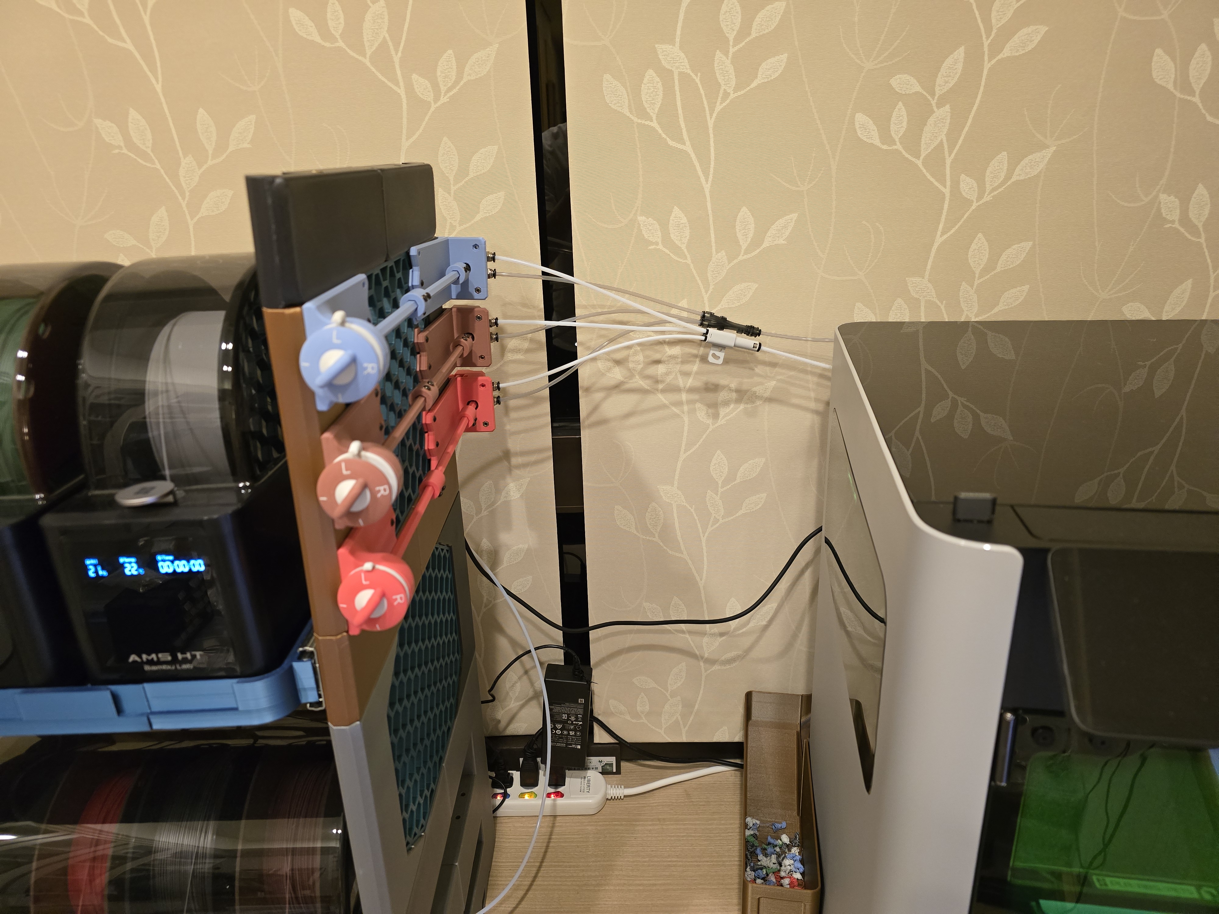
Now connect the AMS, AMS Nozzle Switch Unit, and 3D printer using PTFE tubes.
Connect the PTFE tubes from the AMS Nozzle Switch Unit to the printer:
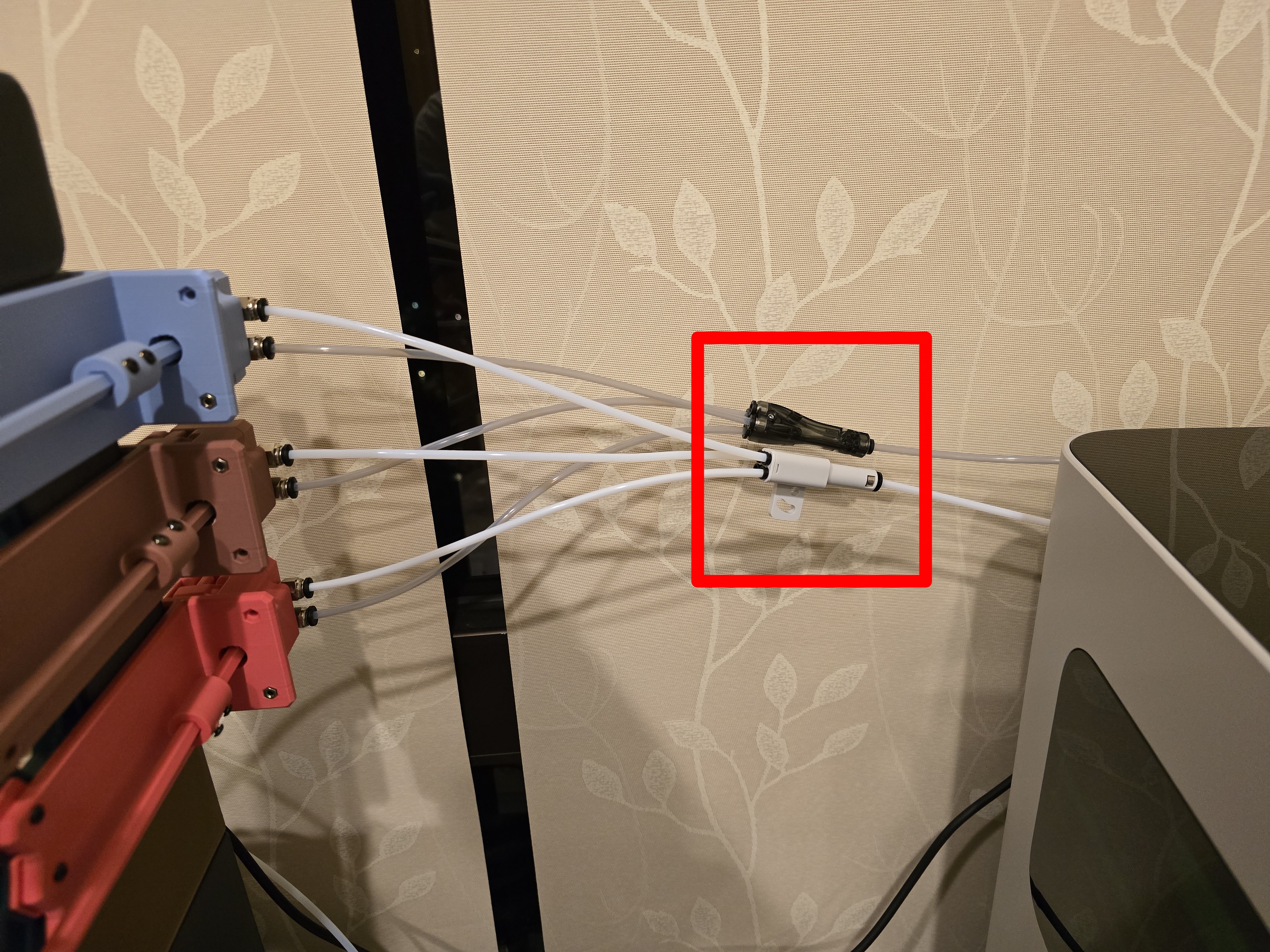
The 3D printer must first be connected with the 4-in-1 PTFE adapters,
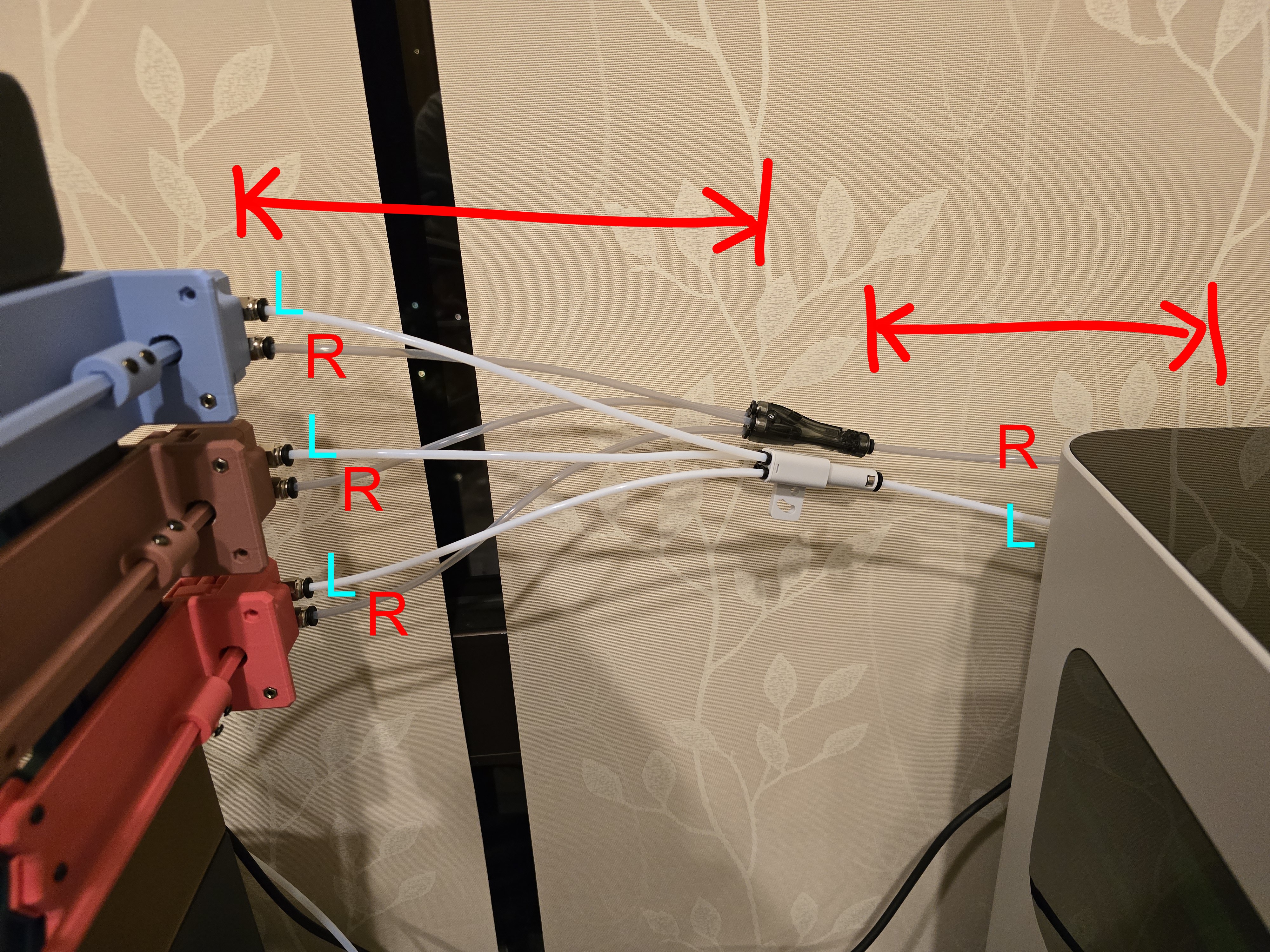
Measure the distance between the pneumatic connectors of the AMS Nozzle Switch Unit and the 3D printer's pneumatic connectors for each nozzle,
Cut PTFE tubes to the appropriate length and connect them,
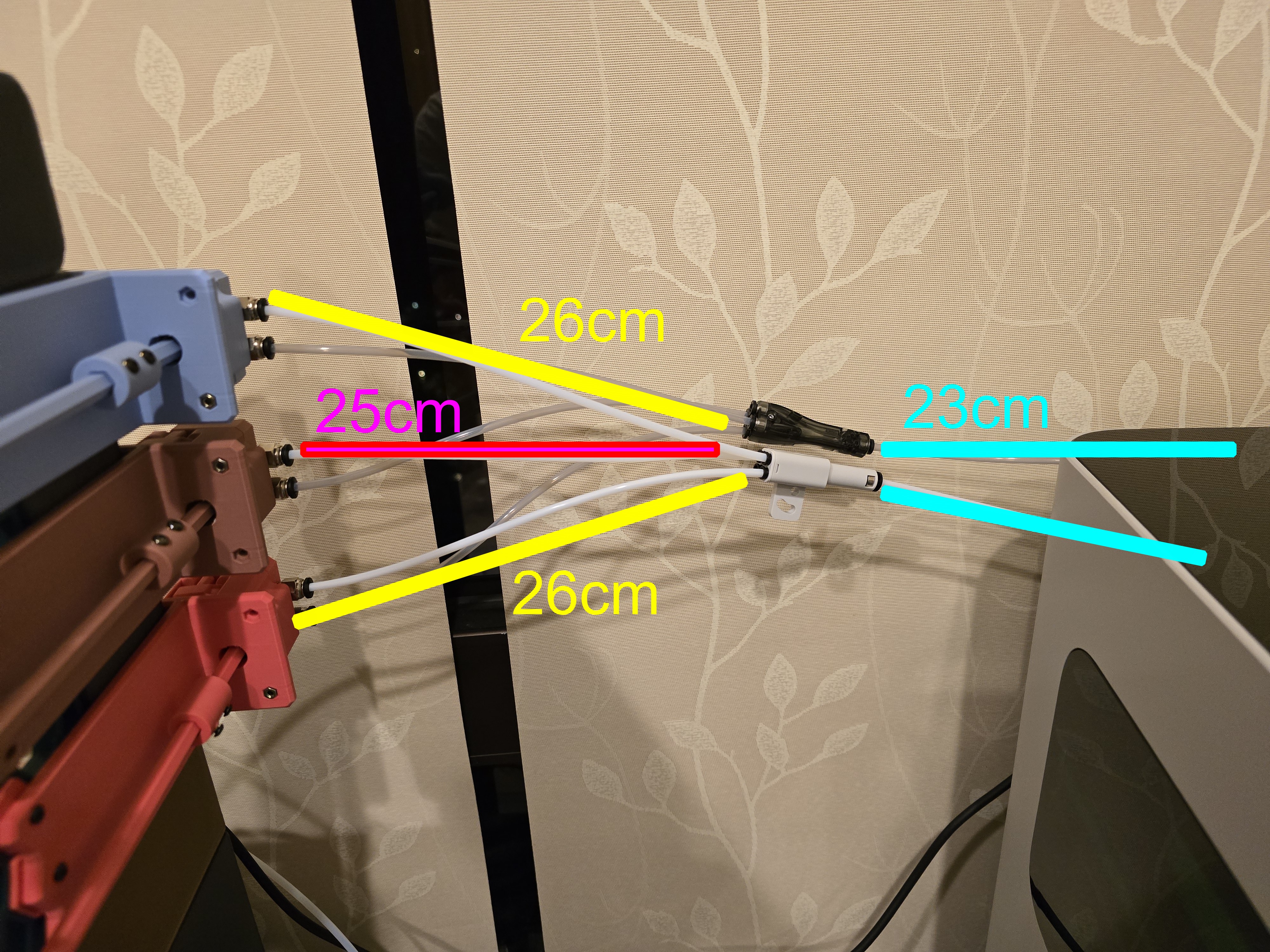
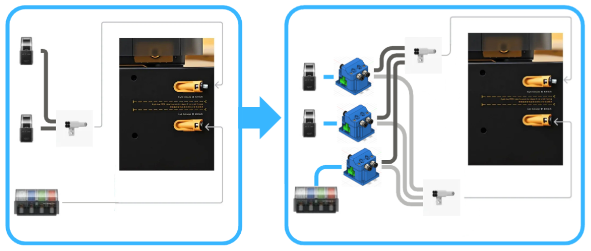
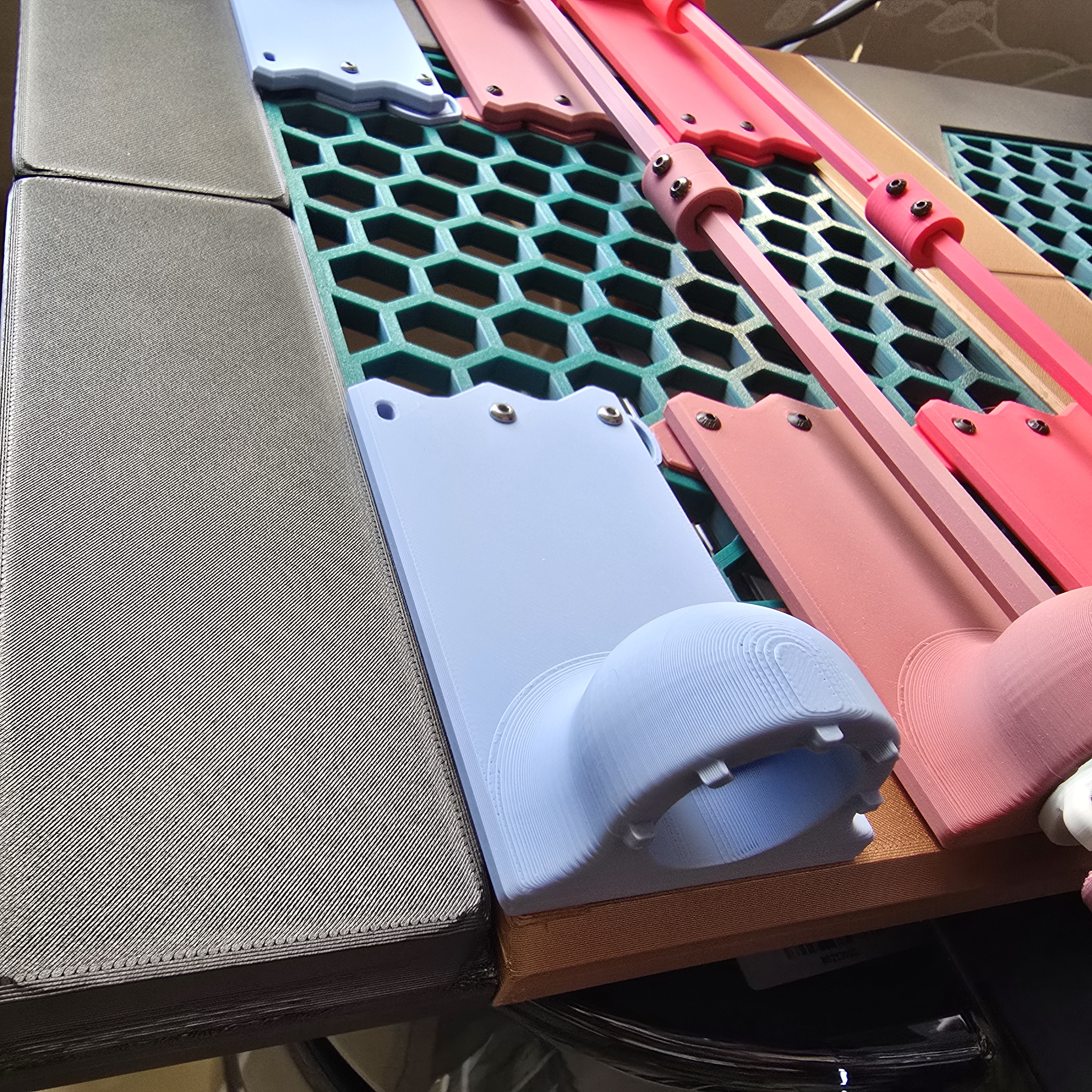
Length reference example based on the above image:
- Connect to the printer's "L" and "R" nozzles through two 23cm PTFE tubes
- Connect the upper and lower AMS Nozzle Switch Units through four 26cm PTFE tubes
- Connect the middle AMS Nozzle Switch Unit through two 25cm PTFE tubes
You can use the observation hole to ensure the PTFE tube is pushed all the way in.
Connect the PTFE tubes from the AMS to the AMS Nozzle Switch Unit:
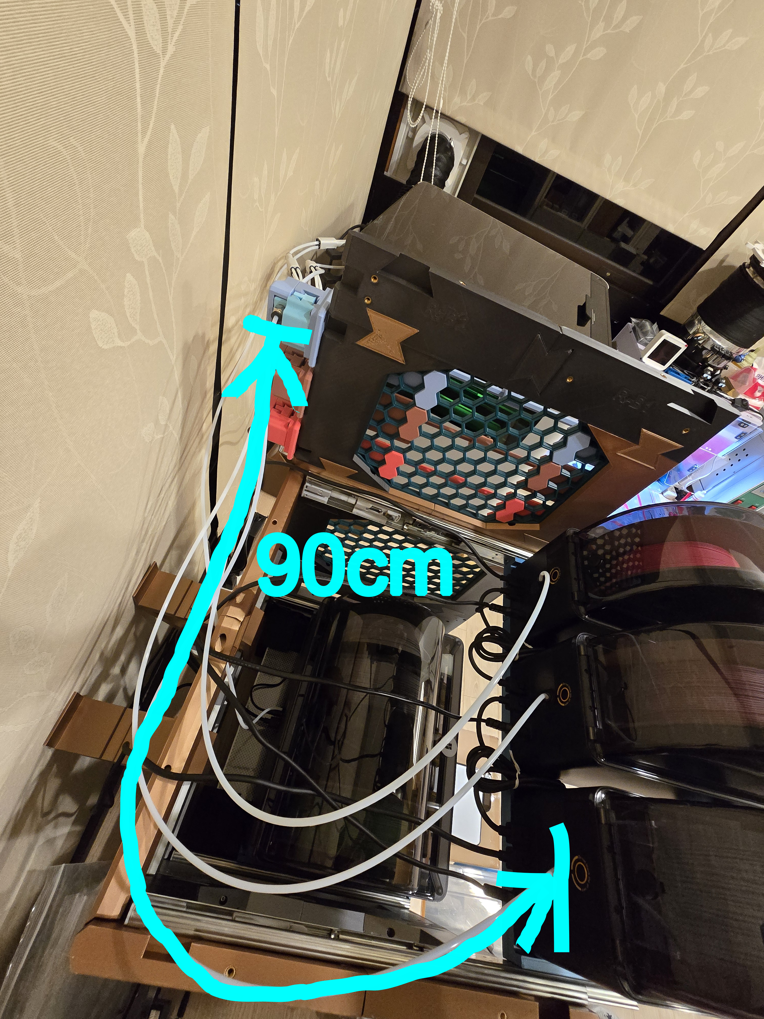
Measure the distance from the AMS Nozzle Switch Unit to the AMS,
Remember to include the distance needed when pulling out the tray,
Cut PTFE tubes to the appropriate length and connect them,
Ensure the PTFE tube is pushed all the way in.
___________________________________________
Check if the connection is successful
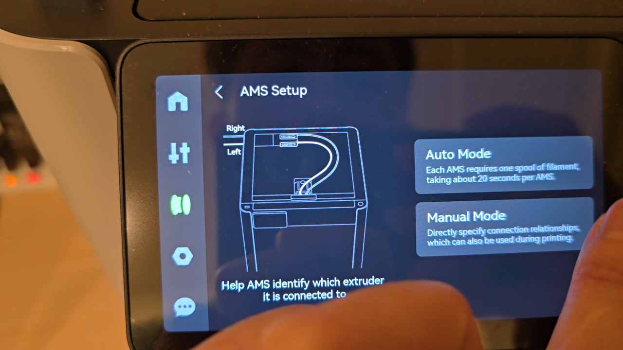
Use the printer's AMS setup function to test if feeding works normally,
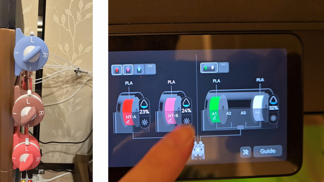
And confirm that the nozzle being fed matches the indicator mark on the knob.
Here is the function demo video -
AMS Multiple Nozzle Switch System

Publicado em 30 de nov de 2025