Você está no 3DFinder
Buscamos em Thingiverse, MakerWorld e Printables ao mesmo tempo para te dar o melhor de cada uma.
Descrição
NOTE:
This model is specifically designed around the specific internal components of the USB Switch and its included controller button I purchased, which I extracted from it's original housing. (See end of post for specific USB Switch info)
I included STEP and .f3d files, since it's highly unlikely this model will accommodate your specific controller button without need for modification.
What?
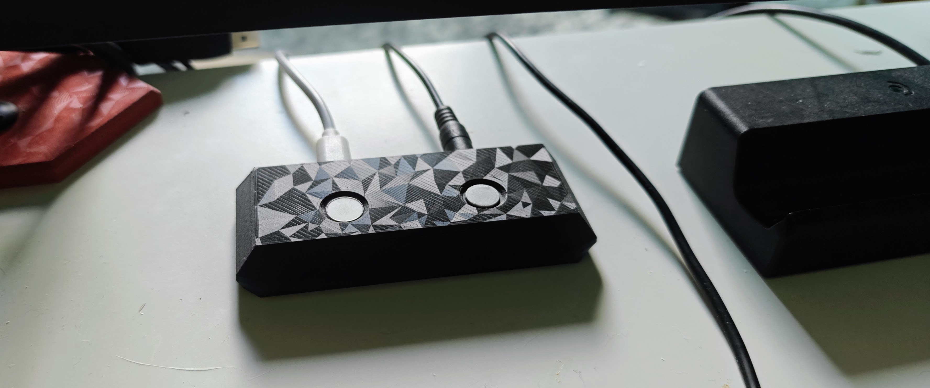
An enclosure for the guts of 1 magic keyboard and one USB switch controller button. The touchid works seamlessly between machines, aside from the delay from the USB switch when swapping devices. It just shows up as a connected magic keyboard, even if it's only powering the one button.
Why?
I got frustrated switching between my laptop for work, which had touchid and my personal mac mini, which didnt. Using my touchid on my laptop also meant it had to be close/on my desk and open for me to be able to use it.
I came across a post mentioning this video and had an idea to combine it with my USB switch that already handles some shared accessories between the two machines.
External Parts:
- 1 Magic Keyboard (tenkeyless)
- Important: make sure it's the smaller, tenkeyless version, or the control board wont fit
- The color and target alphabet doesnt matter
- You can disassemble the keyboard yourself (so. much. glue!) or search eBay for resellers who sets of these parts
- 1 USB/KVM Switch with some kind of stand-alone button to toggle target machines
- see note at the top about the high-specificity of this model
- in my case, the button had a silicone cover held in place by glue, with the bare components (button + 3.5mm port) on a small board
Assembly
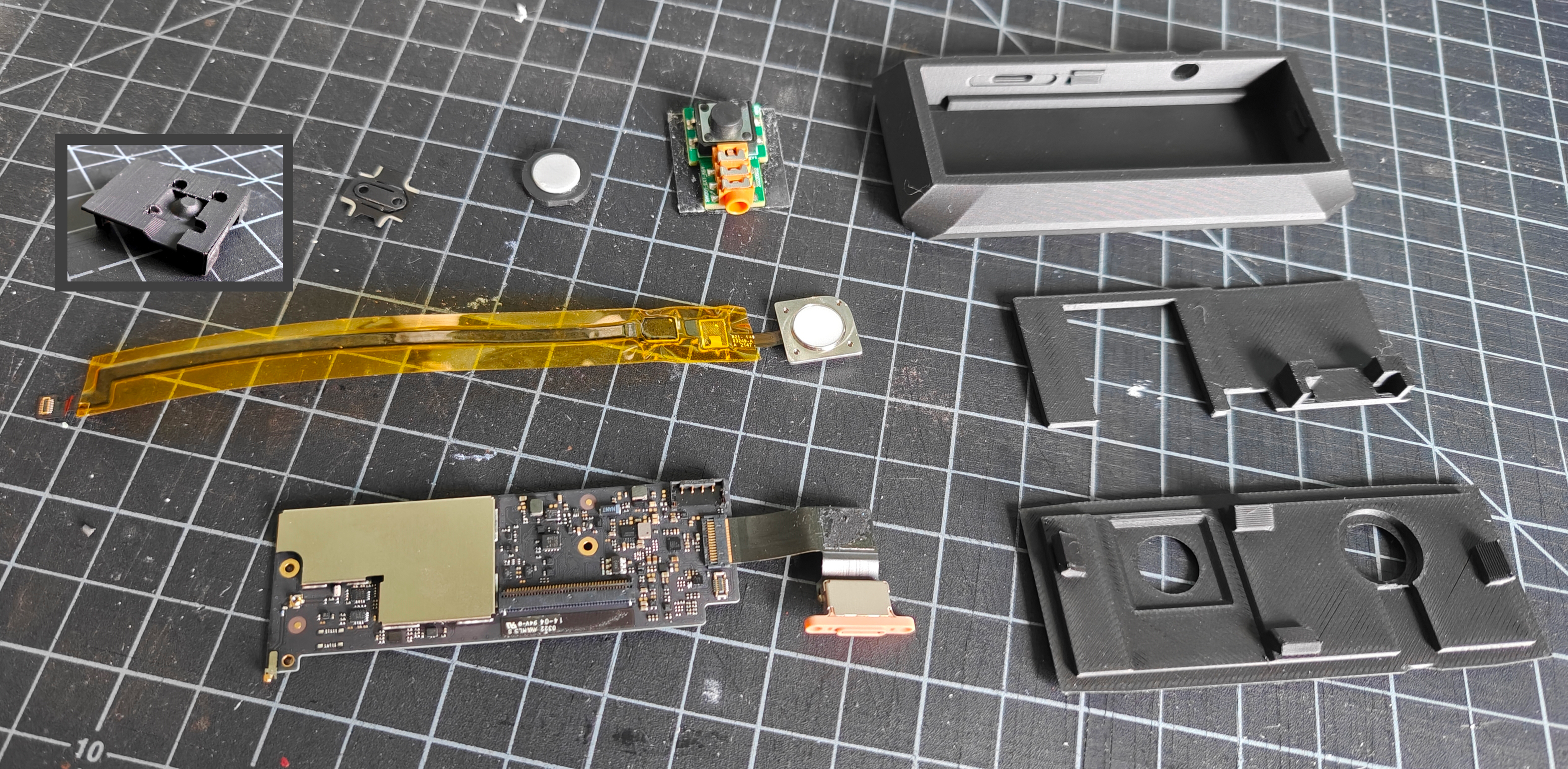
Full parts list:
- prints:
- enclosure base (top right)
- control board divider (center right)
- enclosure top (bottom right)
- touchid base (top left)
- USB/KVM controller button cap (top 3rd-from-left)
- external parts
- USB Switch Controller Button (top 2-from-right)
- the touchid ribbon cable (center left) (see warning note below)
- the control board (bottom left)
- the lighting/usb-c ribbon cable (attached to board)
- the touchid button (attached to ribbon cable)
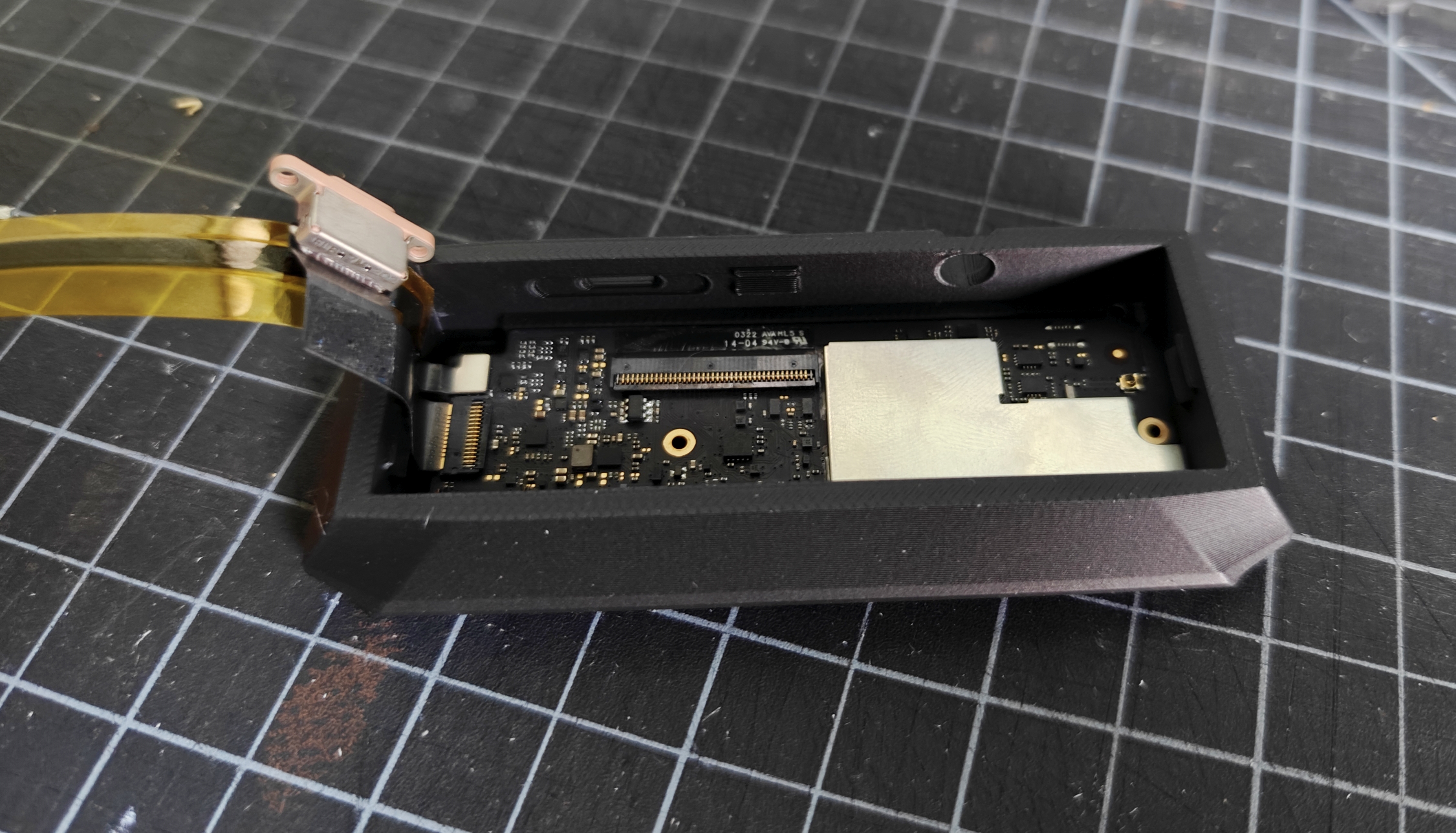
Step 1
With the charge port and touchid ribbon cables attached, insert control board, so the side without the attached cables sits flush with the right side of the enclosure.
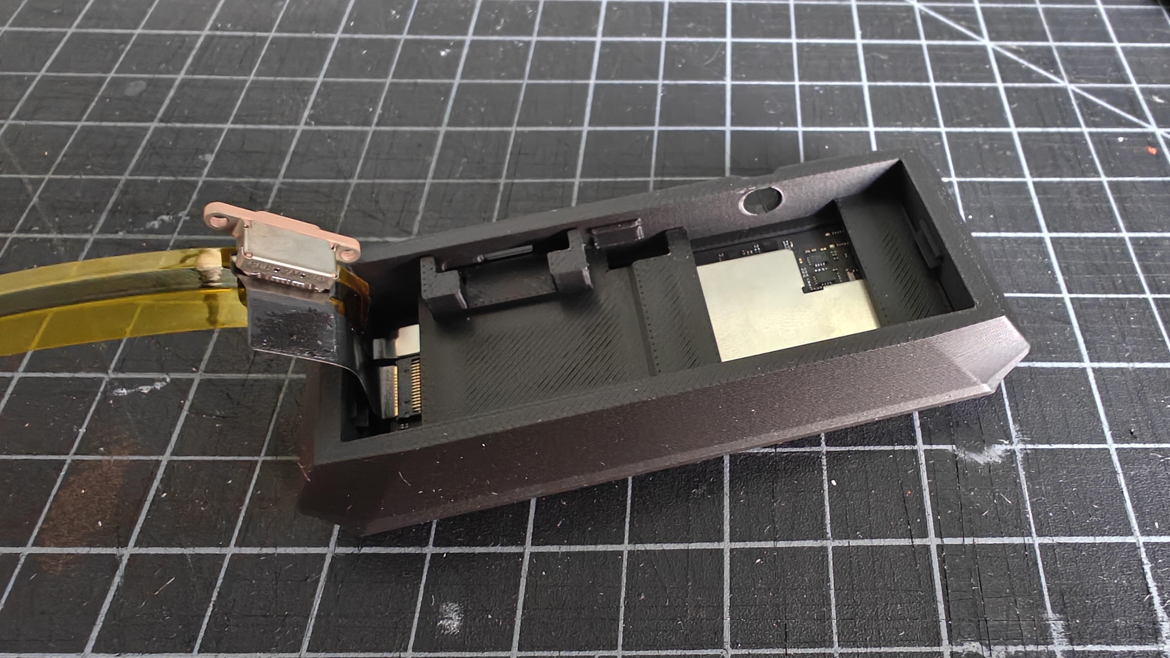
Step 2
With the cables held to the side, insert the divider on top of the control board.
- Orientation: The bracing for the charge port should face the cutout on the back of the enclosure.
- Installation: Lower divider so the cutouts accommodate the snap-fit interfaces on the enclosure, then slide right so it's flush with the right--side wall.
Step 3
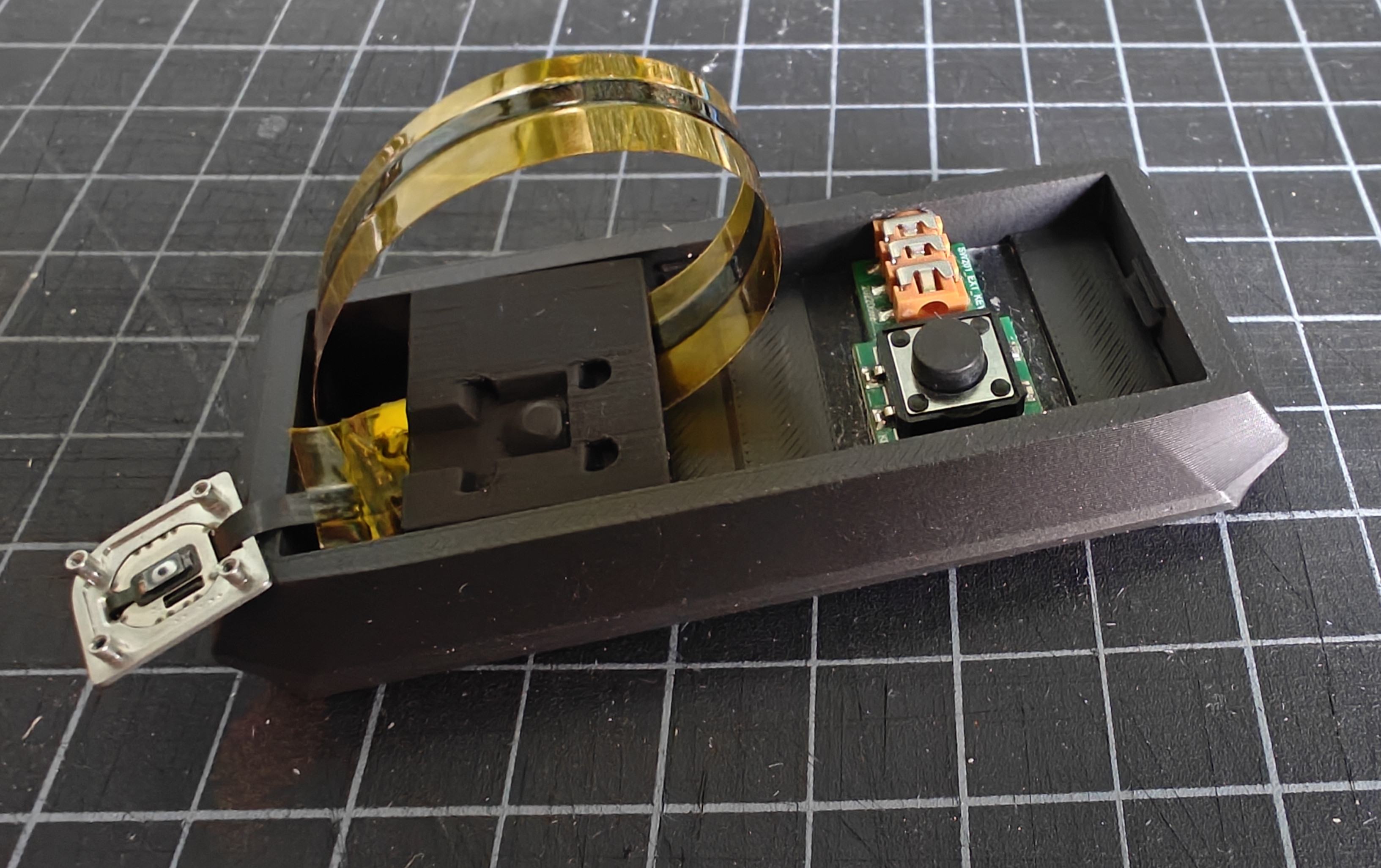
Install the TouchId base. This is the most complex step, since the touchid base has 4 jobs:
- the angled tines on the side directed to the back of the enclosure create a friction-fit for the charge port (more info below)
- the gap it creates behind the port allows for the touch id ribbon cable to safely pass under it, for managing its long length relative to the enclosure
- it positions the touchid mounting stems so they remain centered under the cutout in the enclosure top
- it has a conical point, where the physical switch on the back of the key can be pressed to trigger wake/sleep
Installation :
- fold over the charge port ribbon cable, where its plastic port cover fits within the bracing slot of the divider we installed in the last step (see previous image)
- Create a loop in the touchid ribbon cable as you see in the image.
- Position (but dont yet fully install!) the touchId base, so the angled tines fit between the plastic charging port cover and the divider's bracing.
- only proceed once you're sure the touchId ribbon cable will safely pass under the touchid base (kapton tape highly recommended)
- Firmly press the touchid base down
- this will hold the port tightly against the outer wall and securely fix the base in place.
- this takes a bit of force, but you might also have to trim the tines a bit, depending on your machine's tolerances
- this will hold the port tightly against the outer wall and securely fix the base in place.
- install the USB/KVM button
Step 4
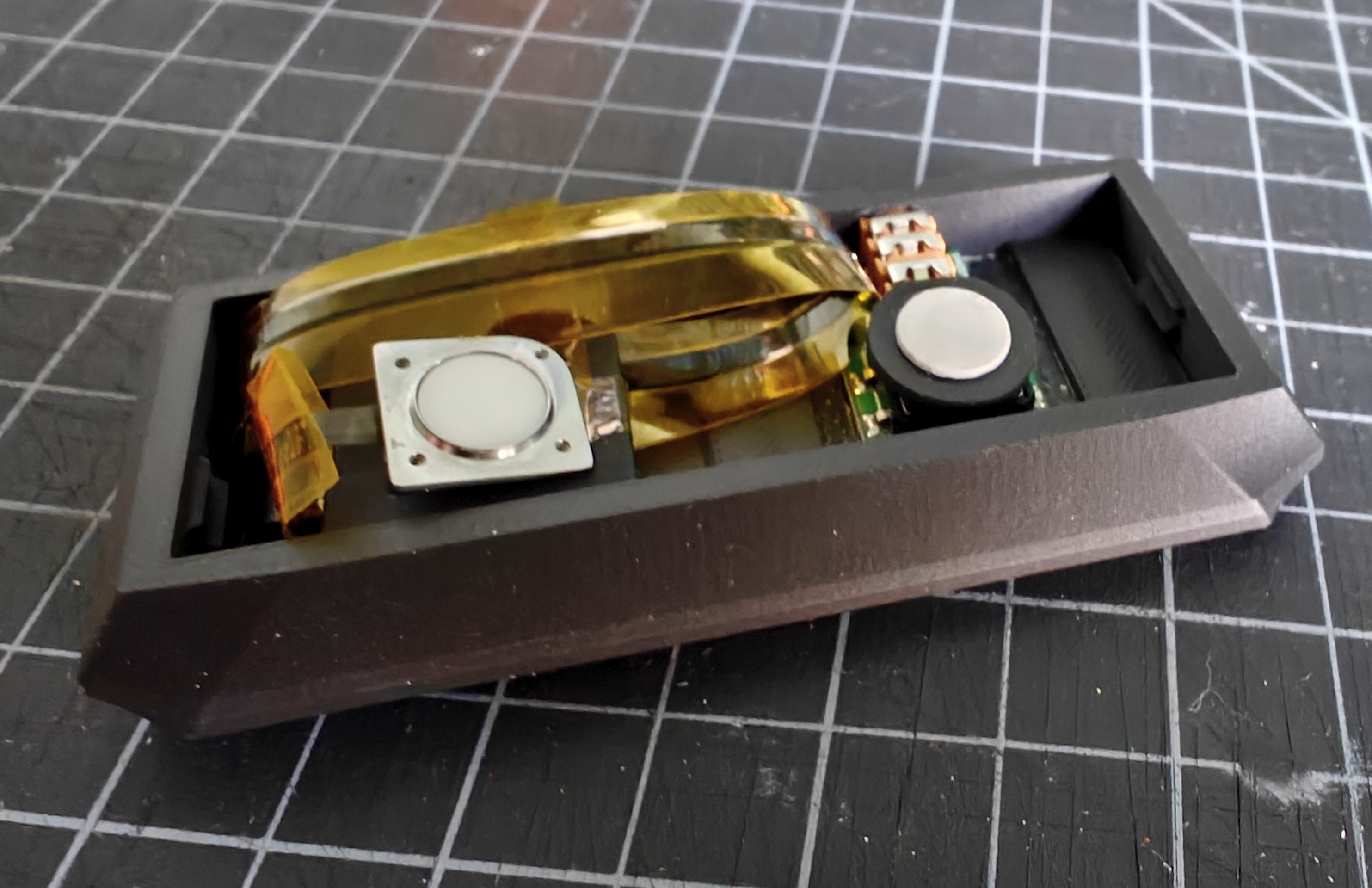
Position buttons:
- Fold over touchid cable, so its mounting posts fit in the 4 reciprocal holes in the base
- Place the USB/KVM button cap on trigger switch
- (Optional) Use some tape to hold the ribbon cable in place, so it's not trying to unwind and dislodge the touchid key while you install the top (highly recommended)
Step 5
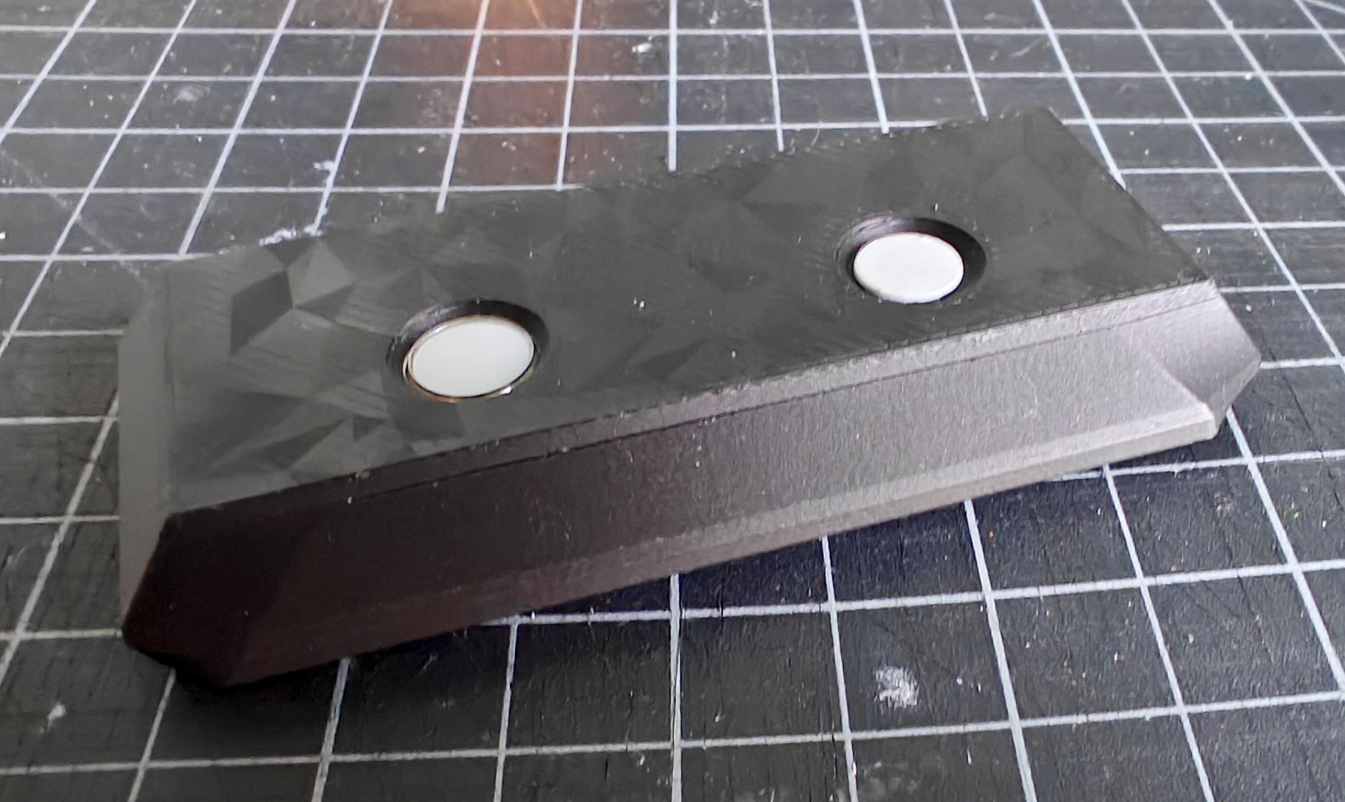
- Carefully lower the enclosure top down over both buttons, so they are centered in the holes. I found it easiest to tilt the top, so the touchId side lowers into place first. This might take some fiddling, especially if the touchid gets dislodged in the process.
- Once in place, firmly press down on the top to ensure all 4 clasps snap together.
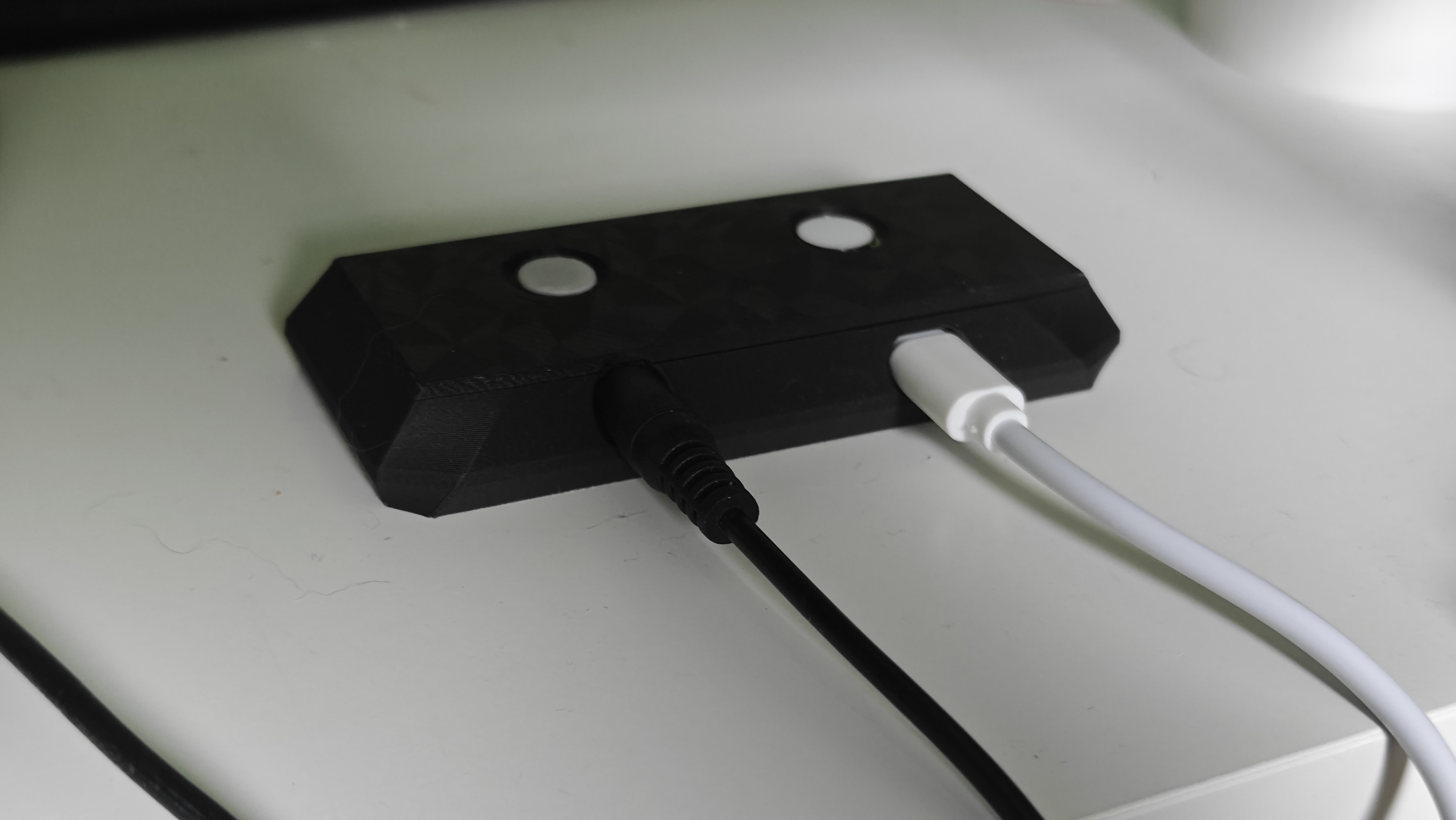
Ports on assembled enclosure
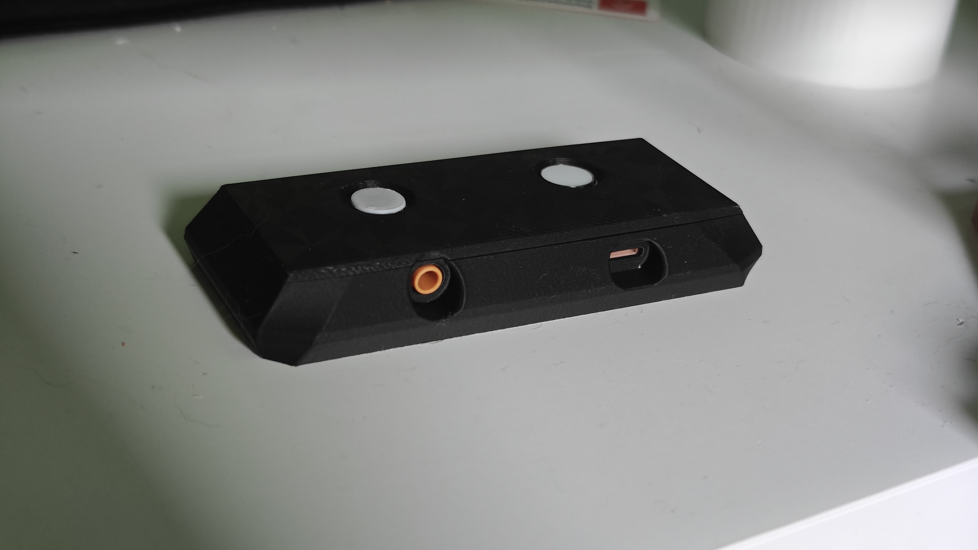
RIBBON CABLE WARNING! The touchid, the keyboard's main chip AND the cable are cryptographically paired in the factory, so while you can just replace the cable if it breaks (ask me how I know) for $5, it wont let you use the fingerprint reader functionality. As you can see in the images, I sandwiched the new ribbon cable in between some kapton tape for extra rigidity. it worked out really well, so i suggest you do the same.
USB switch info
just in case folks wonder, this is the USB switch I'm talking about.
That's is the one i got, but it doesnt seem to be available anymore. Others would work, it's just that the form factor of the controller button will likely be different, which is why the .f3d and STEP files are available to adjust things to fit your USB/KVM controller dimensions.
TouchId + USB Switch Controller Enclosure

Publicado em 20 de set de 2025
Gostou deste modelo? Crie uma conta grátis para salvar seus favoritos e voltar a eles depois.
Criar conta