Você está no 3DFinder
Buscamos em Thingiverse, MakerWorld e Printables ao mesmo tempo para te dar o melhor de cada uma.
Descrição
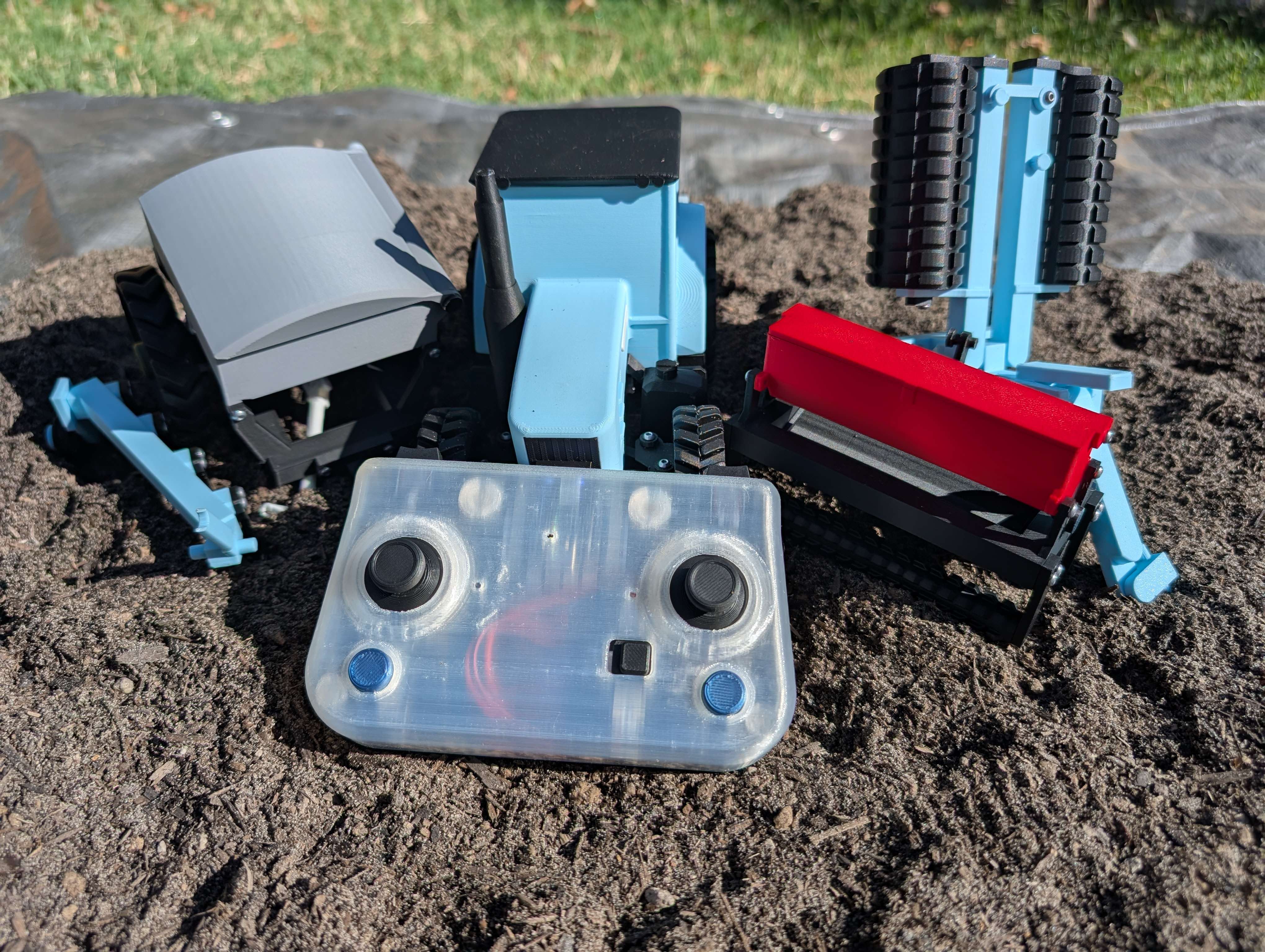
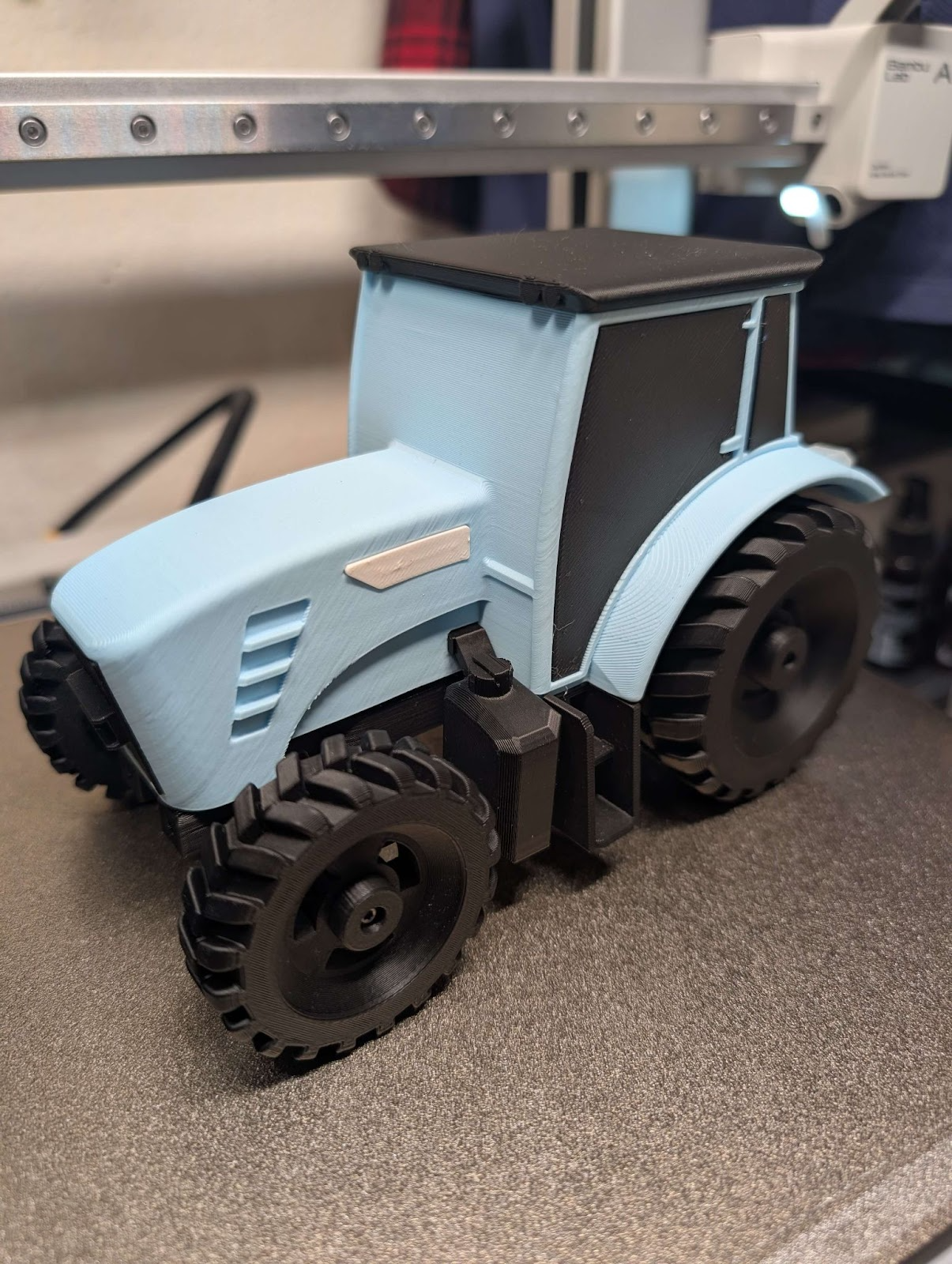
CyberBrick Tractor
Explore how tractors work on a small scale with CyberBricks.
(Attachments will be released over the next few months)
Updates:
- Add the plow attachment. Print can be found in print profiles, instructions found under tractor instructions.
About:
This is my take on bringing tractors to a smaller stage. Originally i was planning on making a 1/10th scale rc car to work with the Open Z standard but i quickly found out that the compatible motors weren't quite powerful enough for me. I tried a few other things but eventually i landed on the idea of tractors. Tractors aren't known for there speed so that wasn't a problem and there are tones of attachments. Also I might have a couple days worth of hours in Farming Sim 22.
The CyberBrick Tractor is now to longest I've ever spent on project and its still not done yet. I still have plans to add even more attachments then what you see in the pictures above. From working on suspension on the open z prototype to working with the CyberBricks electronics this has been the most fun I've had on a project. This is also the first time I've done animated instructions so i hope you enjoy them.
Functionality:
The CyberBrick Tractor Uses two N20 motors and 2 angular servos to provide drive, steering, lights, 3 point hitch movement, and auxiliary motor.
- Drive: ability to move forwards and reverse.
- Steering: ability to turn left and right.
- 3 point hitch movement: ability to move hitch up and down
- Auxiliary motor(optional) : ability to power powered attachments.
Additional Parts:
.N20 Motors 150 RPM And 400RPM(optional) N20 Reduction Gear Motor | Bambu Lab US Store
.200mm SH1.0 cables Wire Pair with SH1.0 | Bambu Lab US Store (the cables the motors come with are way to short)
.Super glue. I use Gorilla glue glue pens.
.Tape or hot glue
Battery safety:
Li-ion battery's a are generally safer then there counterparts Li-po but, they still can be dangerous if not used properly.
Proper Usage: Always use lithium-ion batteries according to the manufacturer's instructions. Avoid using chargers that are not compatible with the battery, as this can lead to overcharging and overheating.
Storage: Store batteries in a cool, dry place away from direct sunlight and heat sources. Avoid exposing them to extreme temperatures, which can increase the risk of thermal runaway (a condition where the battery overheats and can catch fire or explode).
- Inspection: Regularly inspect batteries for signs of damage, such as swelling, leaks, or corrosion. Damaged batteries should be disposed of properly and not used.
Controllers:
CyberBrick Official Standard Remote
(Full usability, Auxiliary motor control is a bit annoying)
CyberBrick Official Standard Remote by CyberBrick MakerWorld: Download Free 3D Models
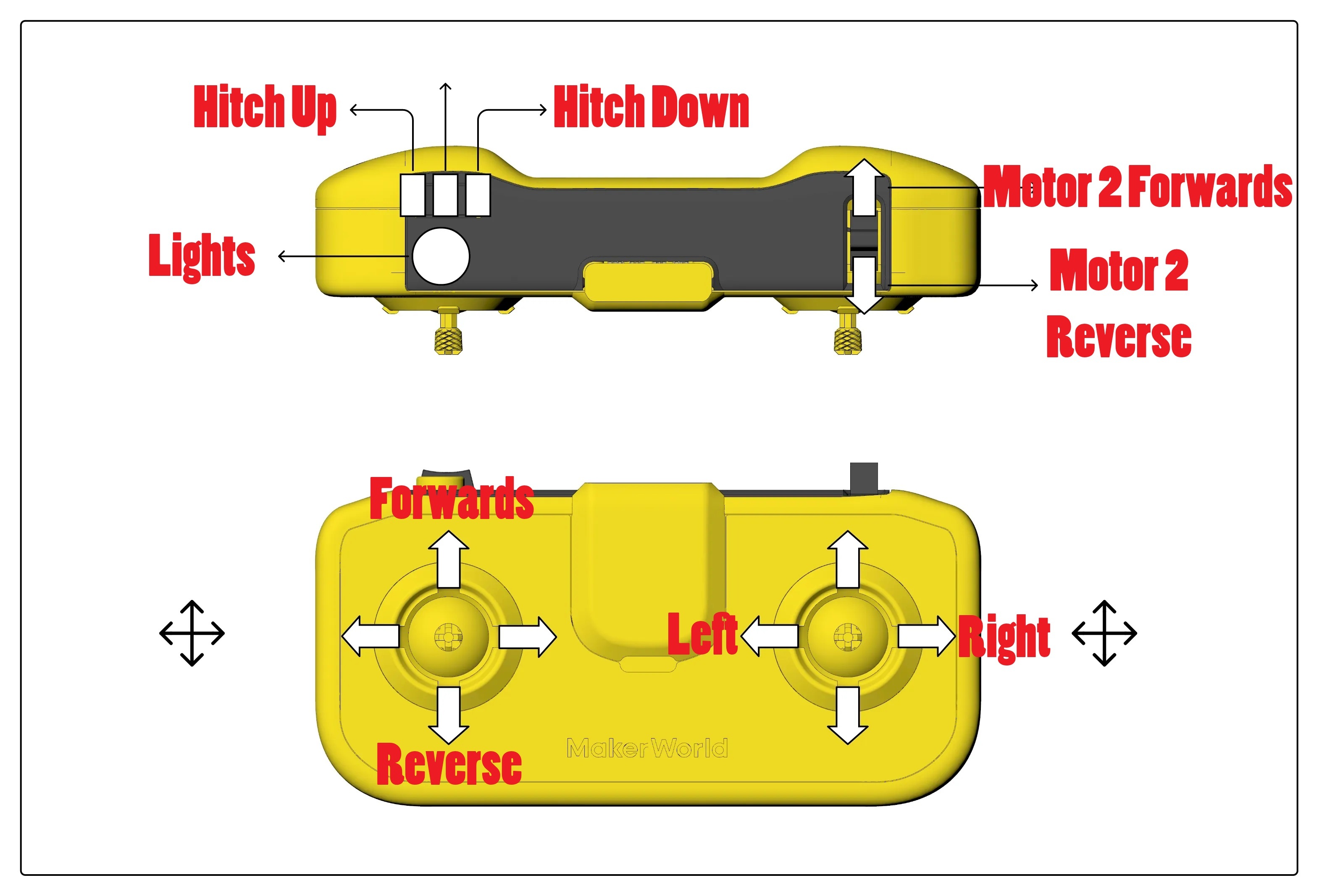
Lights: Press for on Hold for off
Auxiliary motor: you will have to hold joystick down to keep it active.
CyberPad
(Full Functionality)
CyberPad by KMM MakerWorld: Download Free 3D Models
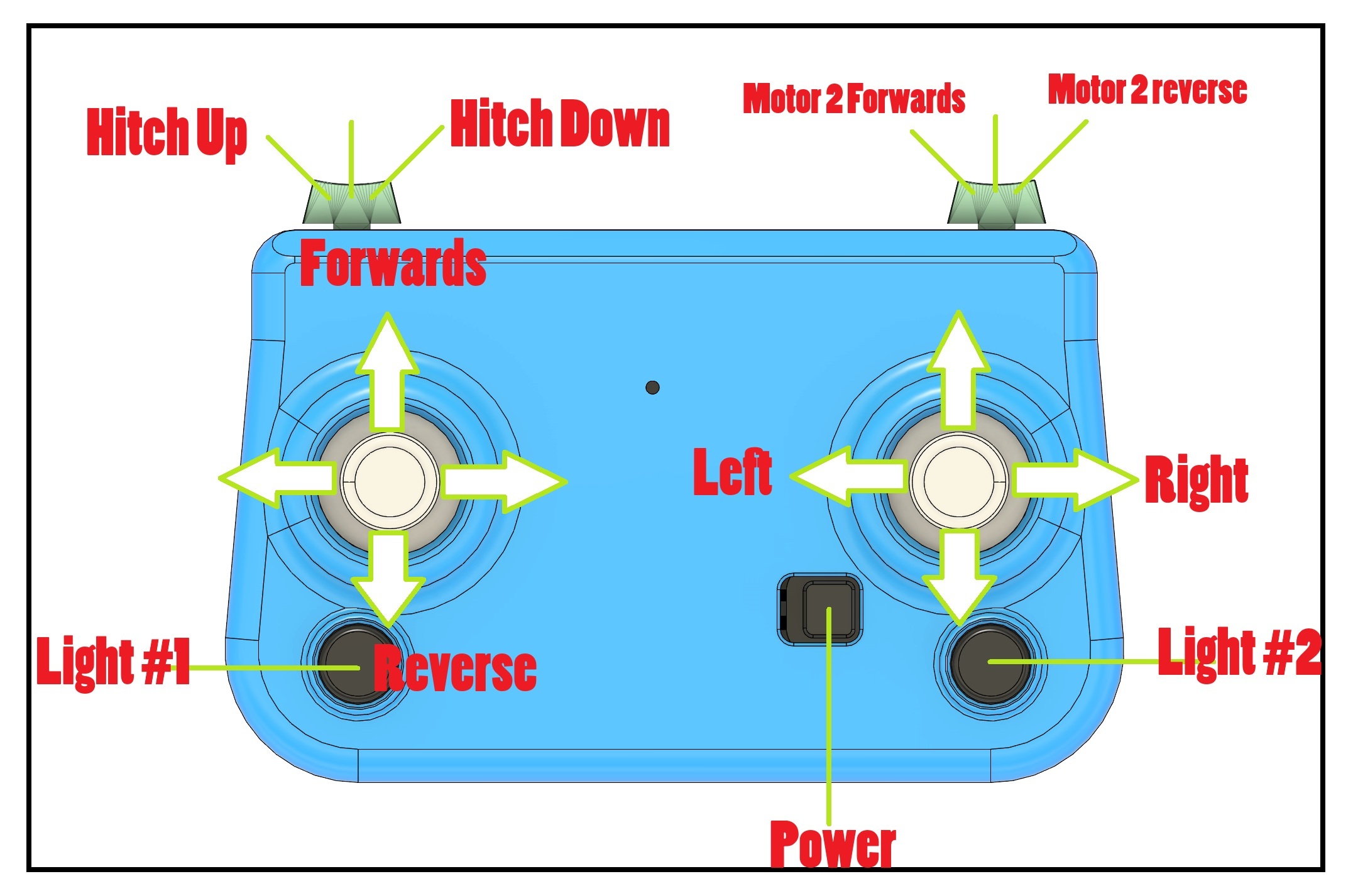
Lights: Press for on Hold for off
Assembly Guide
(Guide is in the Description because Gifs are not compatible with PDF)
:Document guide
Red is a critical warning, and could cause you to reprint or take apart multiple parts if not followed.
Orange is helpful information for steps that require outside resources.
Orange is for extra information about the step.
Underlined means that it is a part
Light Blue Is a servo
Light Green Is a 400RMP N20 motor
There are tons of gifs to help with the main assembly.
For help with cyberbricks app: Software - CyberBrick Apps
(This is going to take awhile:)
Tractor Frame
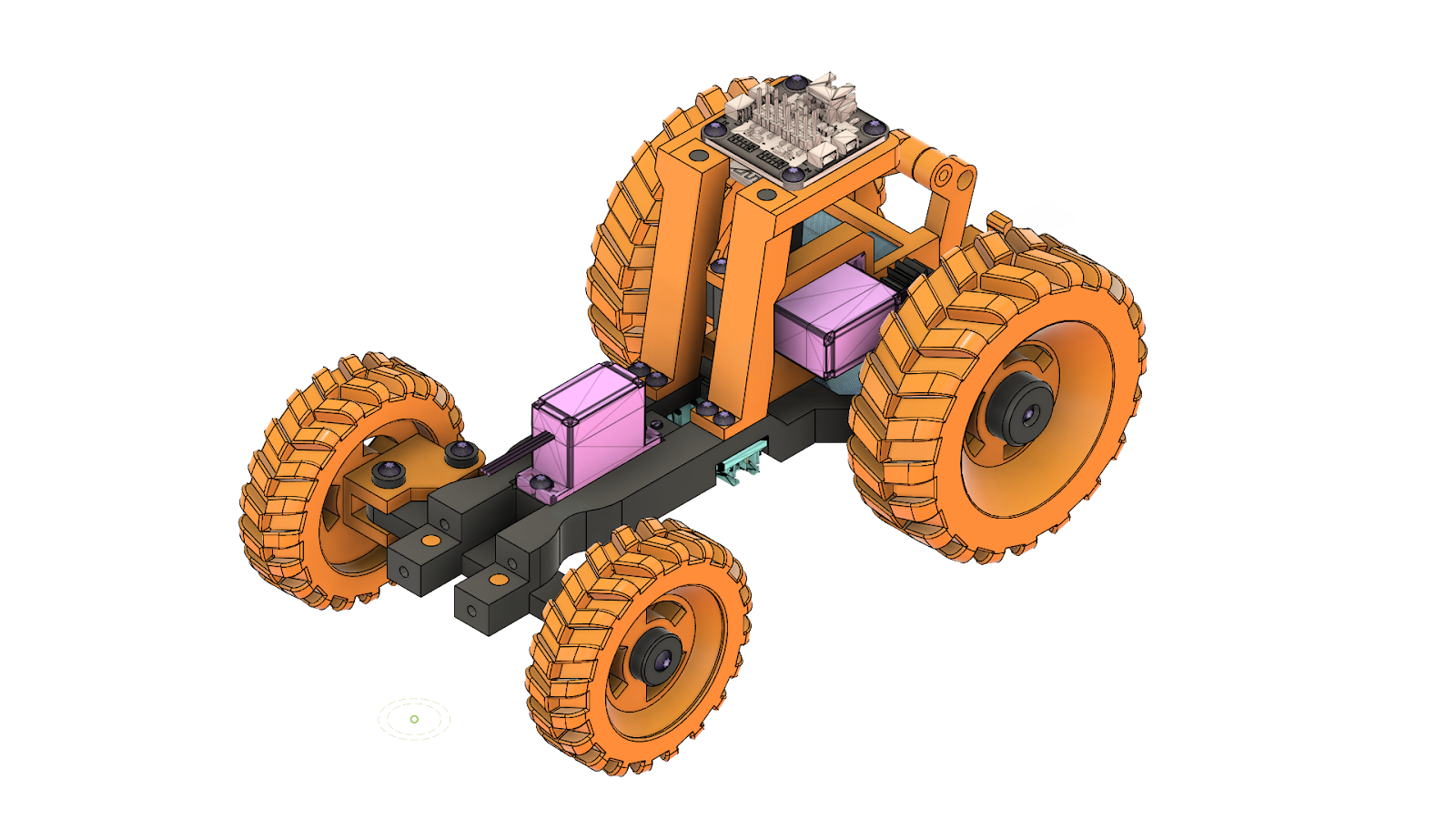
Parts List
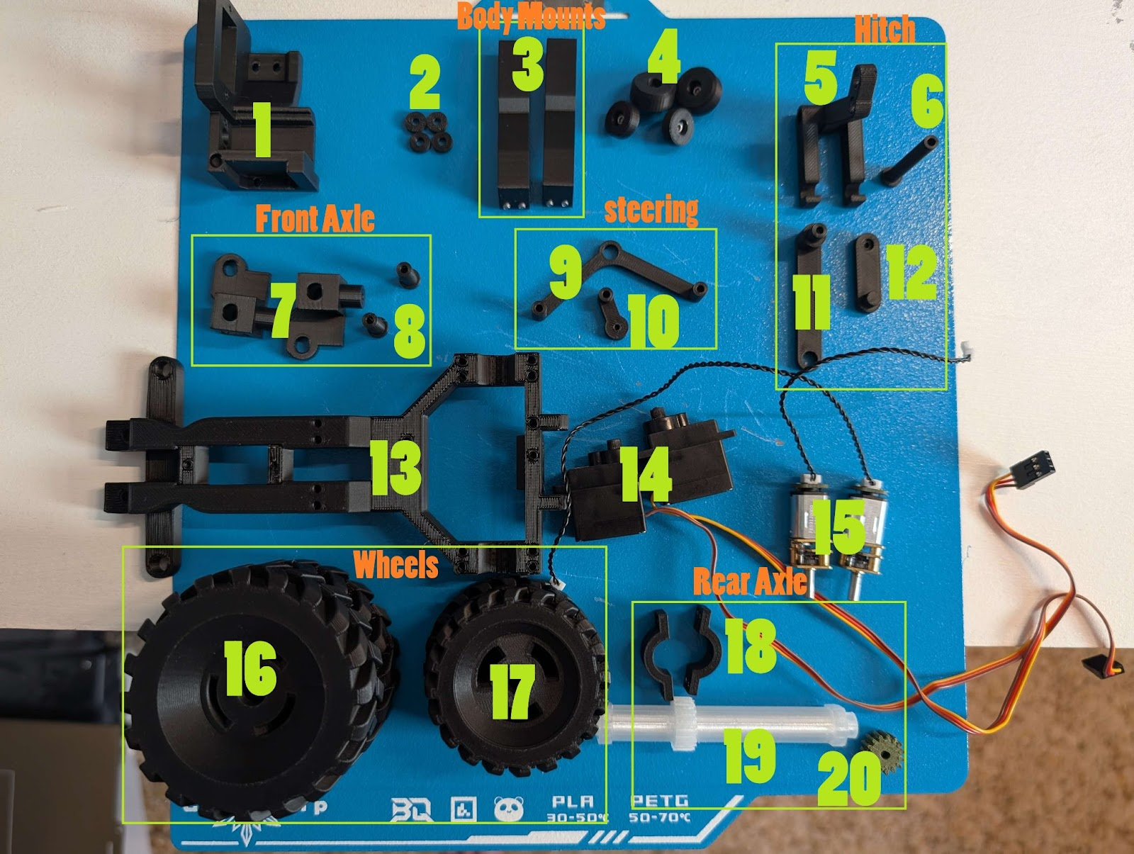
| 1. Motor Mount | 2. Washers x5 | 3. Body Mounts | 4.Wheel Nutsx4 |
|---|---|---|---|
| 5. Hitch | 6. Hitch Bolt | 7. Front Axles | 8. Front Axle Bolts |
| 9.Steering Arm #1 | 10. Steering Arm #2
| 11. Hitch Arm #1 | 12. Hitch Arm #2
|
| 13. Frame | 14. Servos 180 x2 ? | 15. N20 Motors | 16. Rear Wheels x2
|
| 17. Front Wheels x2 | 18. Rear Axle Mounts x2 | 19. Rear Axle | 20. Drive Gear |
Additional Parts
In addition you will also need the receiver, power switch, 2.5mm screws, and the 4x2mm magnets all supplied in the kit.
.N20 Motors 150 RPM And 400RPM? N20 Reduction Gear Motor | Bambu Lab US Store
.200mm SH1.0 cables Wire Pair with SH1.0 | Bambu Lab US Store
.Super glue. I use Gorilla glue glue pens.
Part Information
.400RPM N20 Motor is optional. It will only be used to power some of the external attachments I'm working on.
.The Servos are labeled as PG001 and come in the kit
.200mm SH1.0 cables should be plugged into the N20 motors before installed.
Step #1
Inset 150RPM motor(15) into motor mount(1) and use included screws to secure it.
Step #2
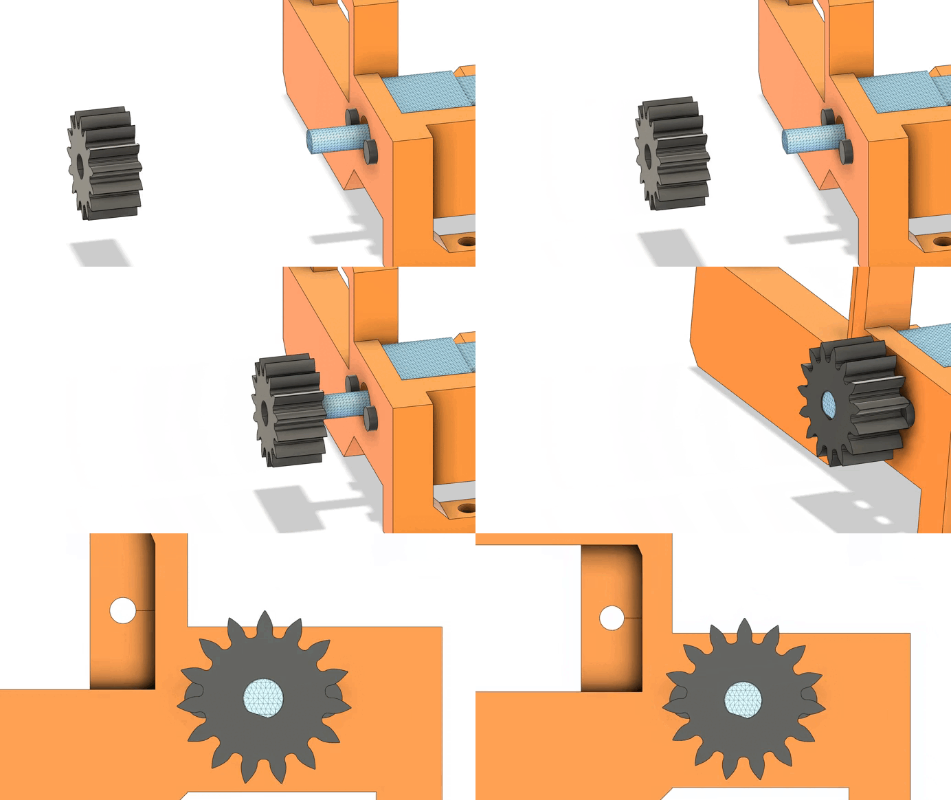
Press Drive Gear(20) on motor(15).
Step #3
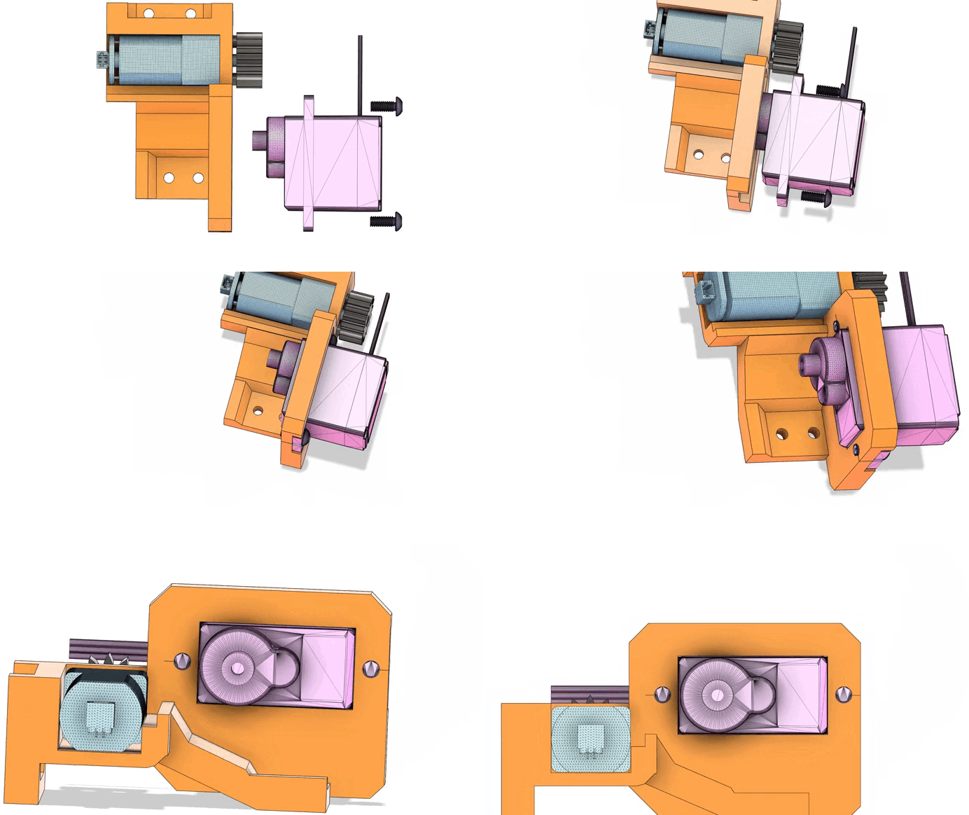
Inset Servo(14) into the motor mount(1) and use the included longer screws to secure it.
Step #4
Place Rear Axle(19) on the Frame(13).
Step #5
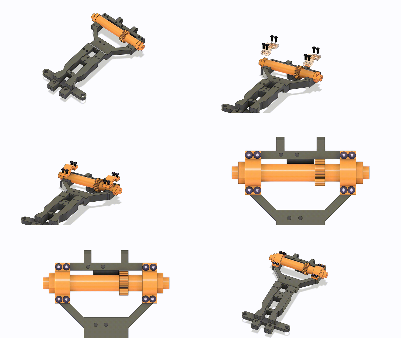
Place Rear Axle mounts(18) on the frame(13) and use 2.5mm screws to secure them.
Step #6
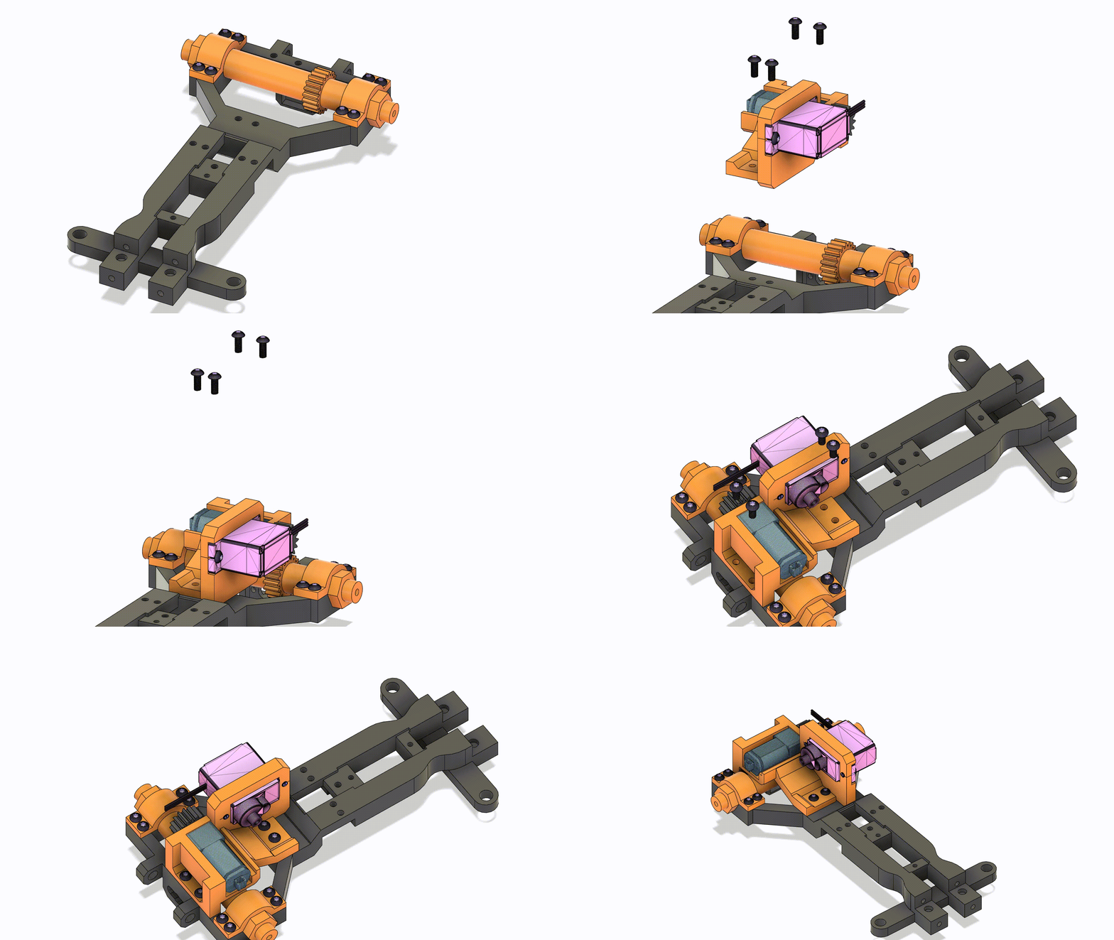
Place Motor Mount Assembly(1) on the frame(13) and use 2.5mm screws to secure it.
Step #7
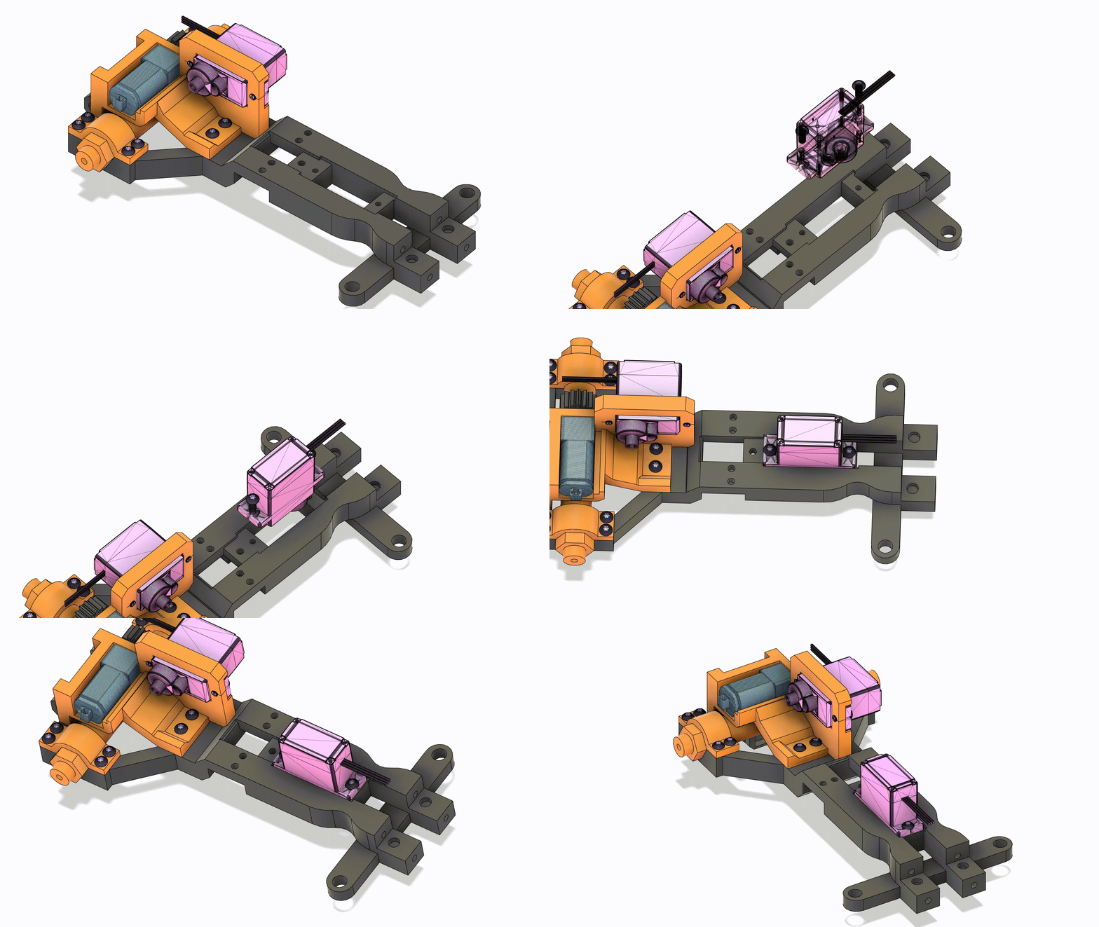
Place your second Servo(14) on the frame(13) and use the included longer screws to secure it
Step #8
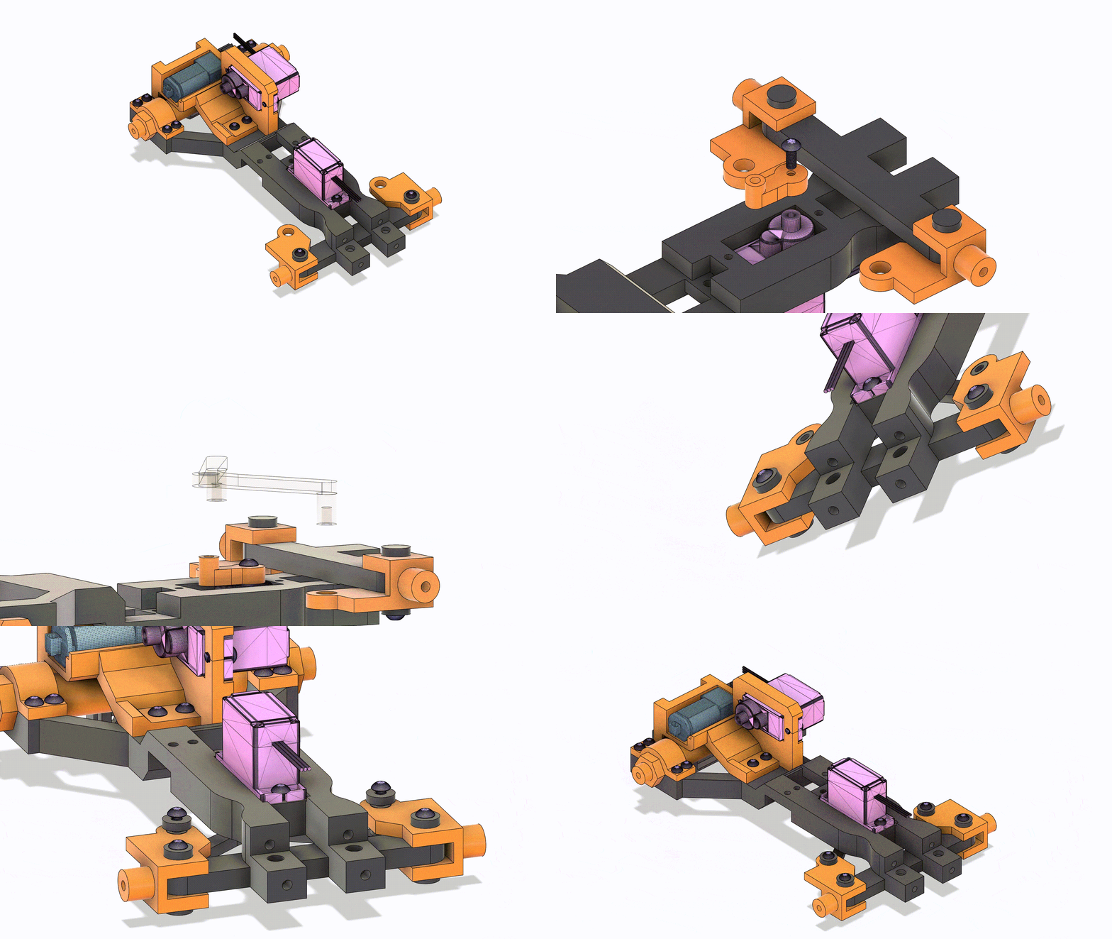
First, slide Front axles(7) on Frame(13). Then, press the Axle Bolts(8) through the Front axles(7) and the Frame(13). Finally, screw a Washer(2) and a 2.5mm screw Into the axle Bolts(8) to secure the whole assembly. Repeat on both sides.
Step #9
First, press Steering Arm #2(10) on the Servo(14) and use the included small screw to secure it. Then, Press the Steering Arm #1(9) on the Steering Arm #2(10) and threw the holes on the Front Axles(7). Finally, use washers(2) and 2.5mm Screws on the top side of Steering Arm #1(9).
Step #10
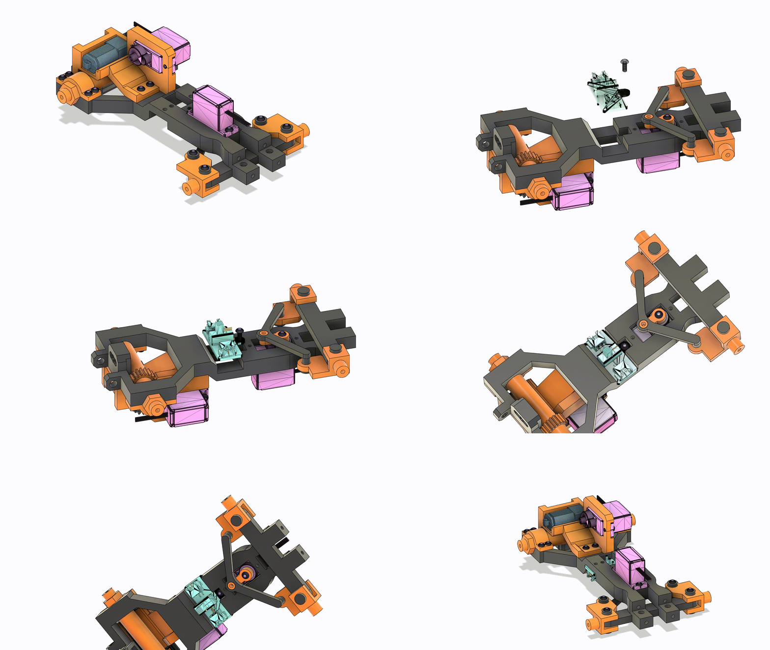
Place the power switch on the bottom side of the frame(13) and use a 2.5mm screw to secure it.
Step #11(optional)
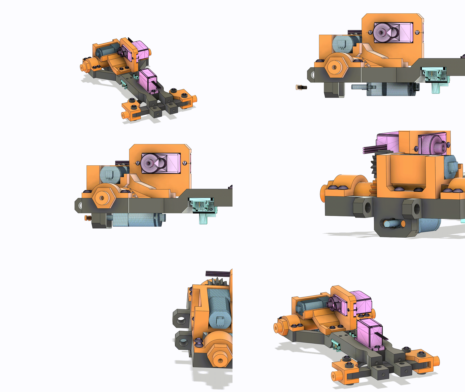
Place 400RPM Motor(15) into the frame(13) and secure it with the included screws.
Step #12
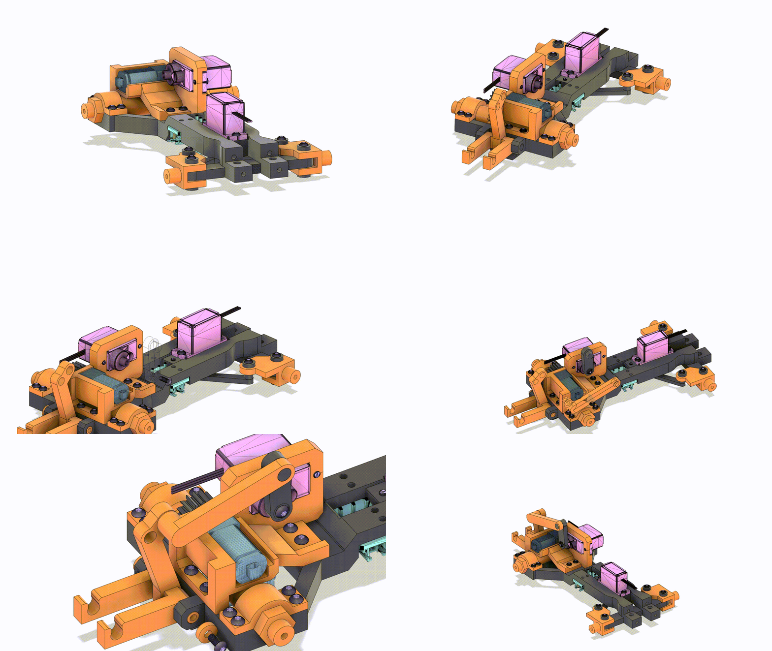
First, slide the Hitch(5) on to the Frame(13) and press the hitch bolt(6) through the Frame(13) and the Hitch(5). Next, Press Hitch Arm #2(12) on the Servo(14) and use the included short screw to secure it. Then, press Hitch Arm #1(11) on to Hitch Arm #2(12) and the Hitch(5). Finally, screw a washer(2). and a 2.5mm screw on to the Hitch Bolt(6).
Step #13
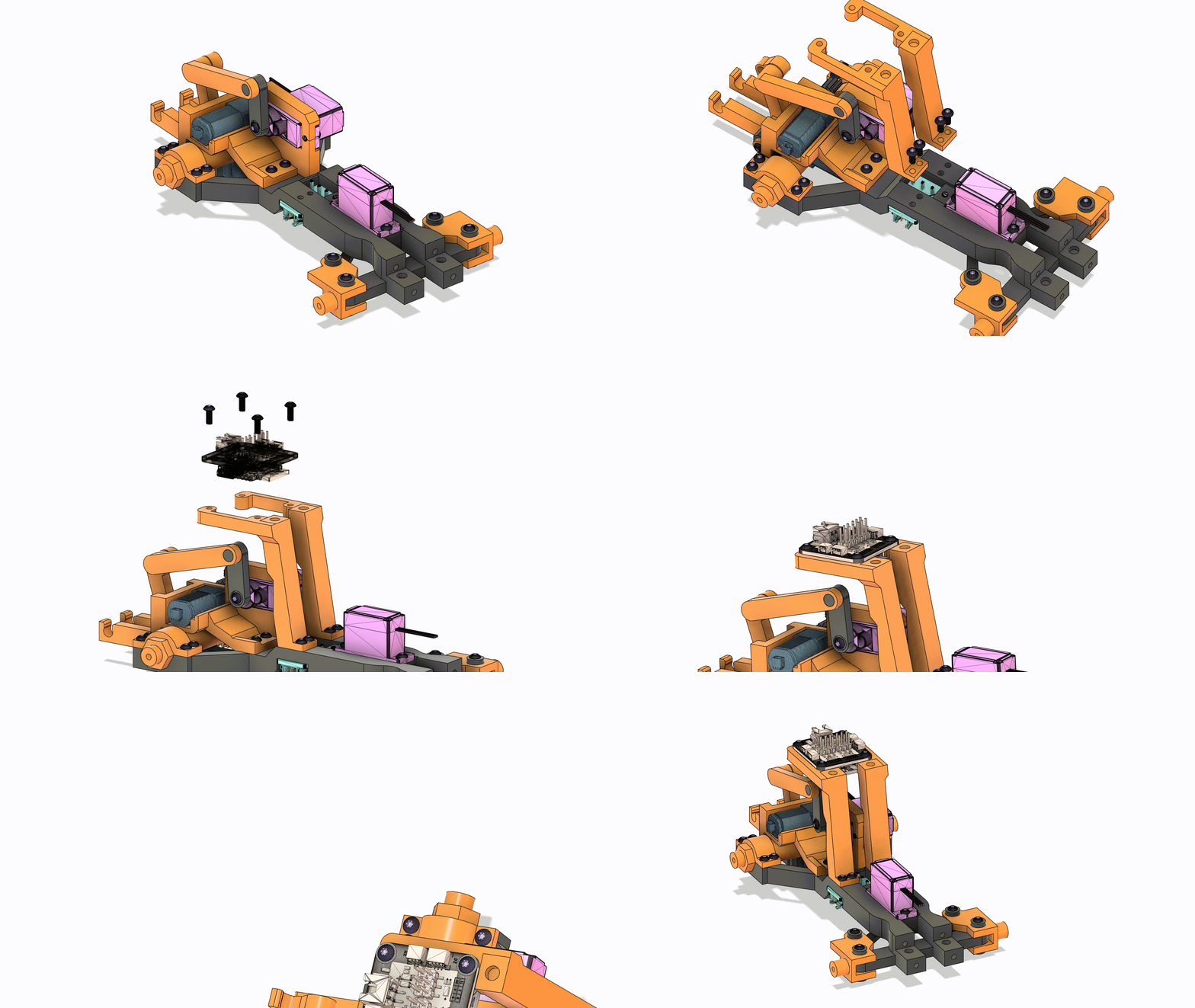
Place Body Mount(3) onto Frame(13) and use 2.5mm screws to secure it. Then, Place the Receiver on the Body Mount(3) and use 2.5mm screws to secure it.
Step #14
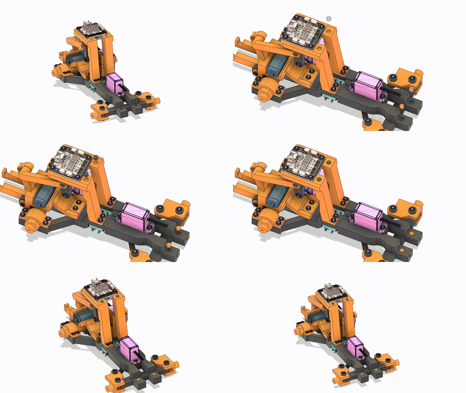
Put a small dab of glue in each magnet hole and then insert the magnets. Press them down to ensure a close to flush fit.
Step #15
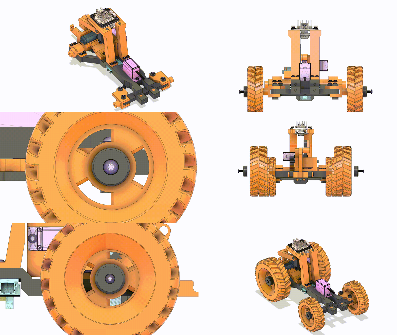
Press Wheels(16)(17) on the axles(7)(19). Then, use a Wheel nut(4) and a 2.5mm screw to secure them.
Do this for all 4 wheels. The bigger Wheel nuts(4) go in the rear.
Tractor Body
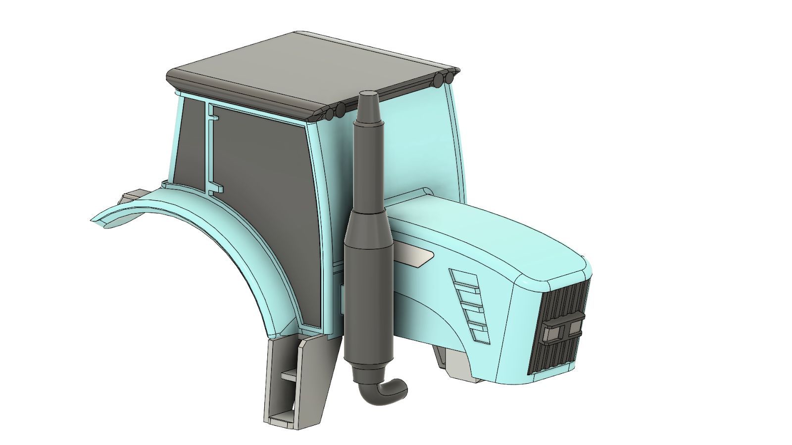
Parts List
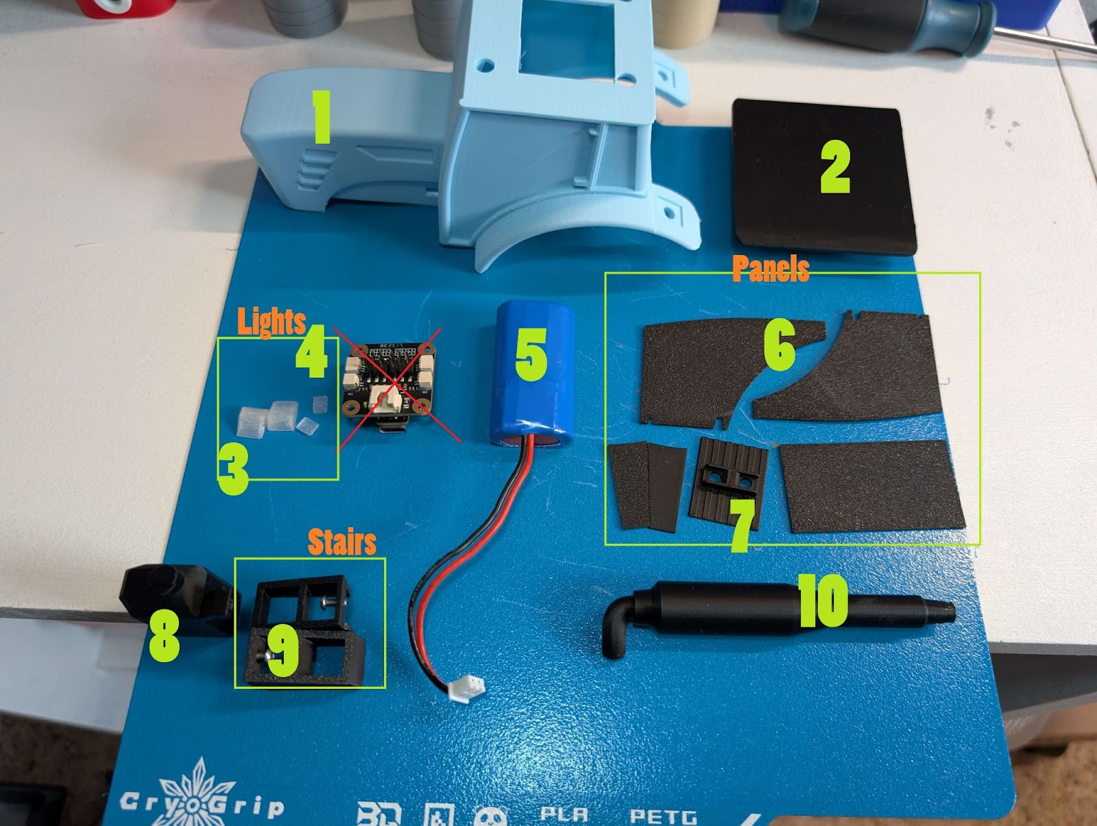
| 1. Body | 2. Roof | 3.Rear Lights | 4.Front Lights | 5. Battery |
| 6. Windows | 7. Front Light assembly | 8. Tank | 9.Stairs | 10. Exhaust |
Additional Parts
.Super glue. I use Gorilla glue glue pens.
.Side pieces, small accent pieces that fit into the holes on the front of the body
.Tank Retainer, a rectangle that has a hole in it. Holds on the tank
Step #1
Add a small dab of glue to the Body(1) and then press magnets in. Press them down to ensure a close to flush fit.
!!Make sure the magnets are facing the right way before installing!! The side attracted to the magnets on the frame go on the outside.
Step #2
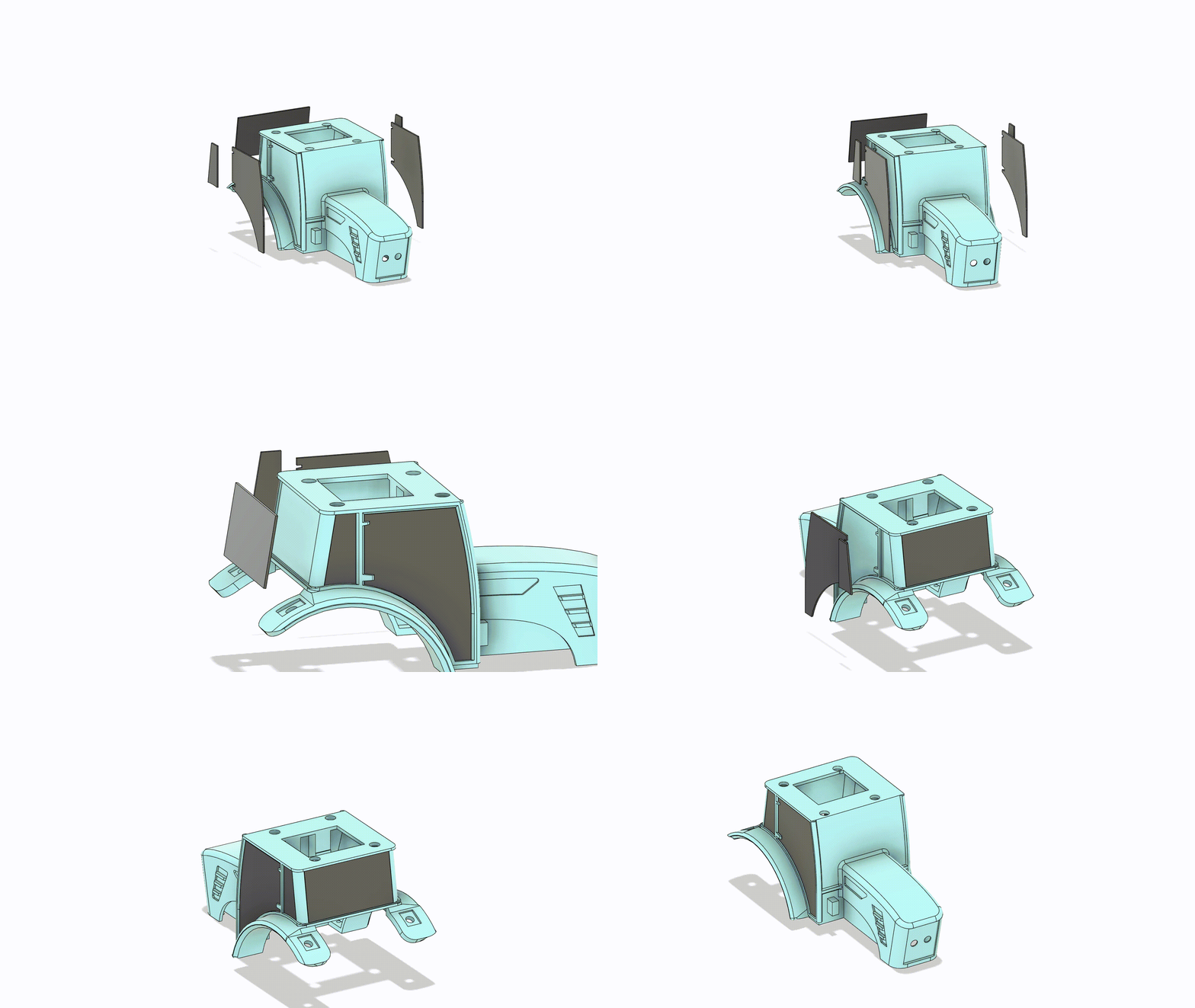
Dab 1 to 3 small bits of glue (optional) on the body(1) then press each Window(6) on the Body(1). The widows(6) will stay on without glue but, that doesn't mean they will never fall off
Step #3
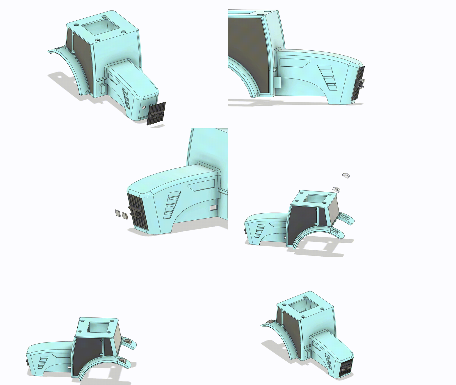
First, Dab 2 to 4 small bits of glue (optional) on the Body(1) then press the Front Light Assembly(7) on the Body(1) Next, put a dab of glue on the Front Lights(4) and press them into the Front Light Assembly(7) Finally, move to the back and put a dab of glue on the Rear Lights(3) and press them on to the Body(1)
Step #4
Press the Tank(8) in the rectangle hole on the Body(1) Then from the inside of the Body(1) use the Tank Retainer and a 2.5mm screw to secure it.
Step #5
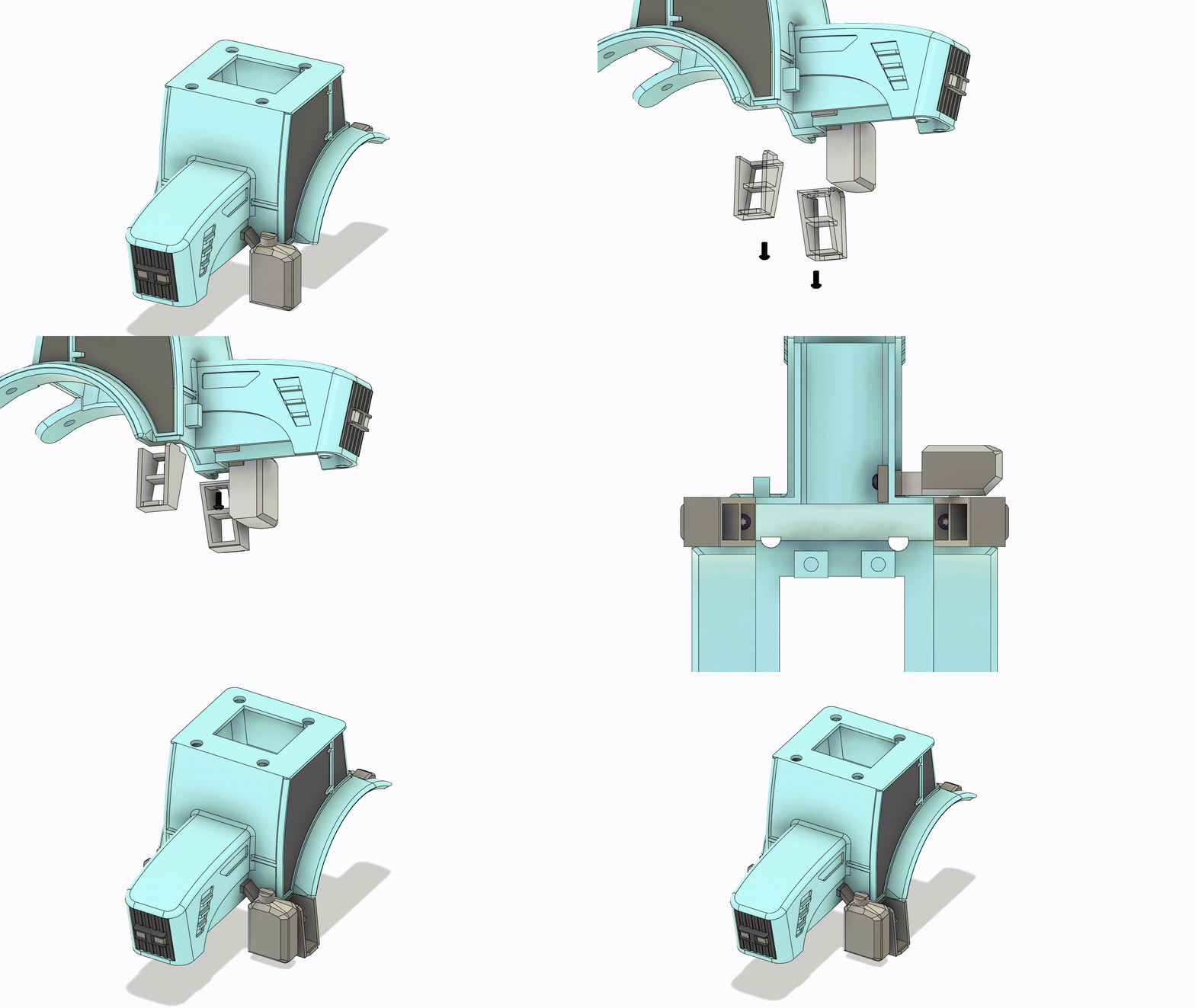
Place each Stair(9) on the bottom of the Body(1) and secure them with a 2.5mm screw.
Step #6
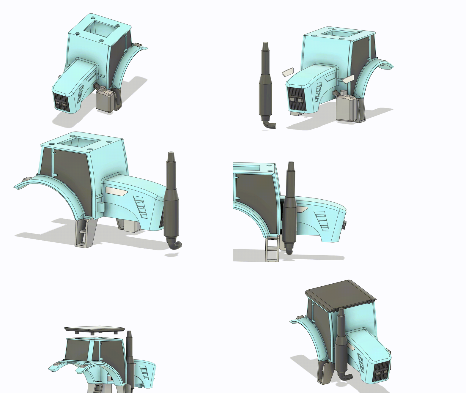
First, Dab 1 to 3 small bits of glue (optional) on the Body(1) then press each Side Piece onto the Body(1). Then, put a Dab of glue in the hole on the Exhaust(10) and press it on the Body(1). Finally, The Roof(2) can be pressed on.
Step #7
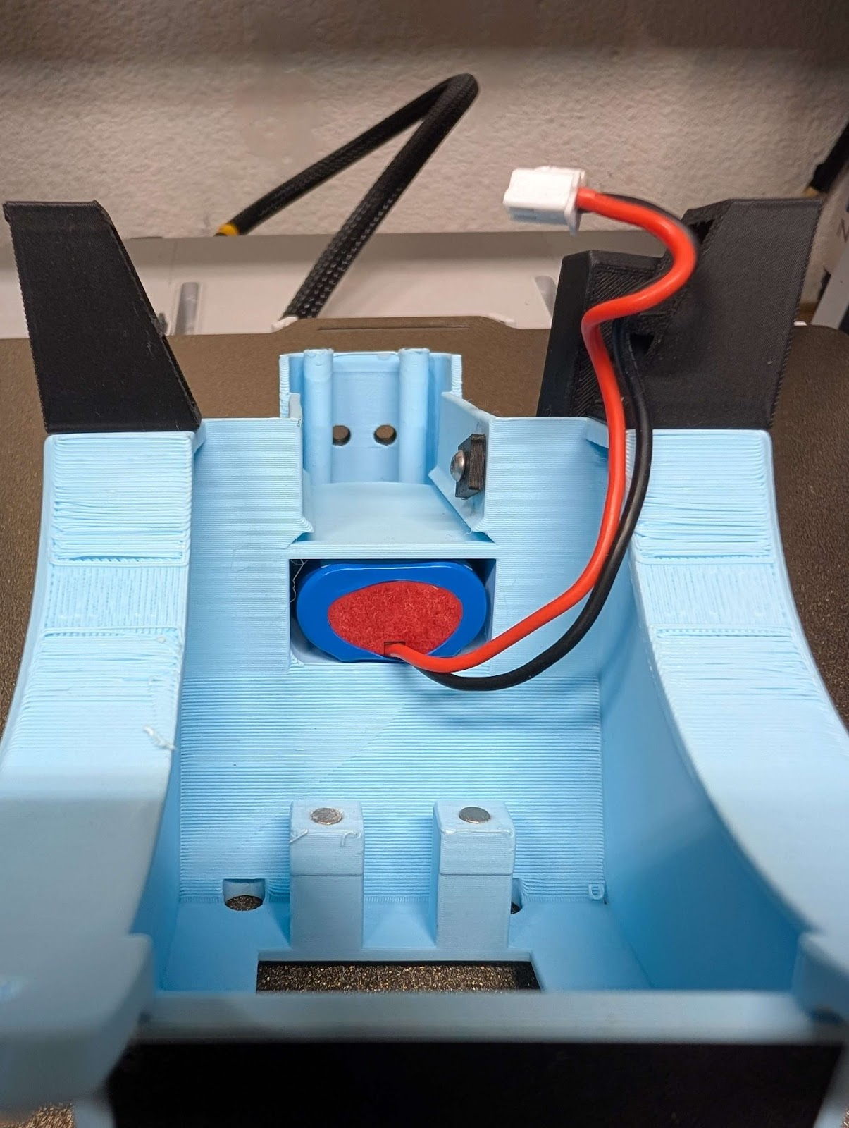
Insert Battery(5)
Electronics and Final Construction
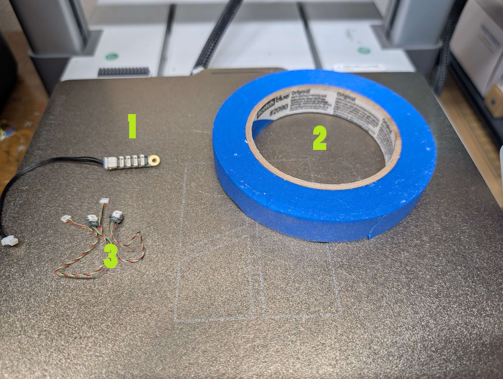
Parts
|
|
|
Receiver Diagram
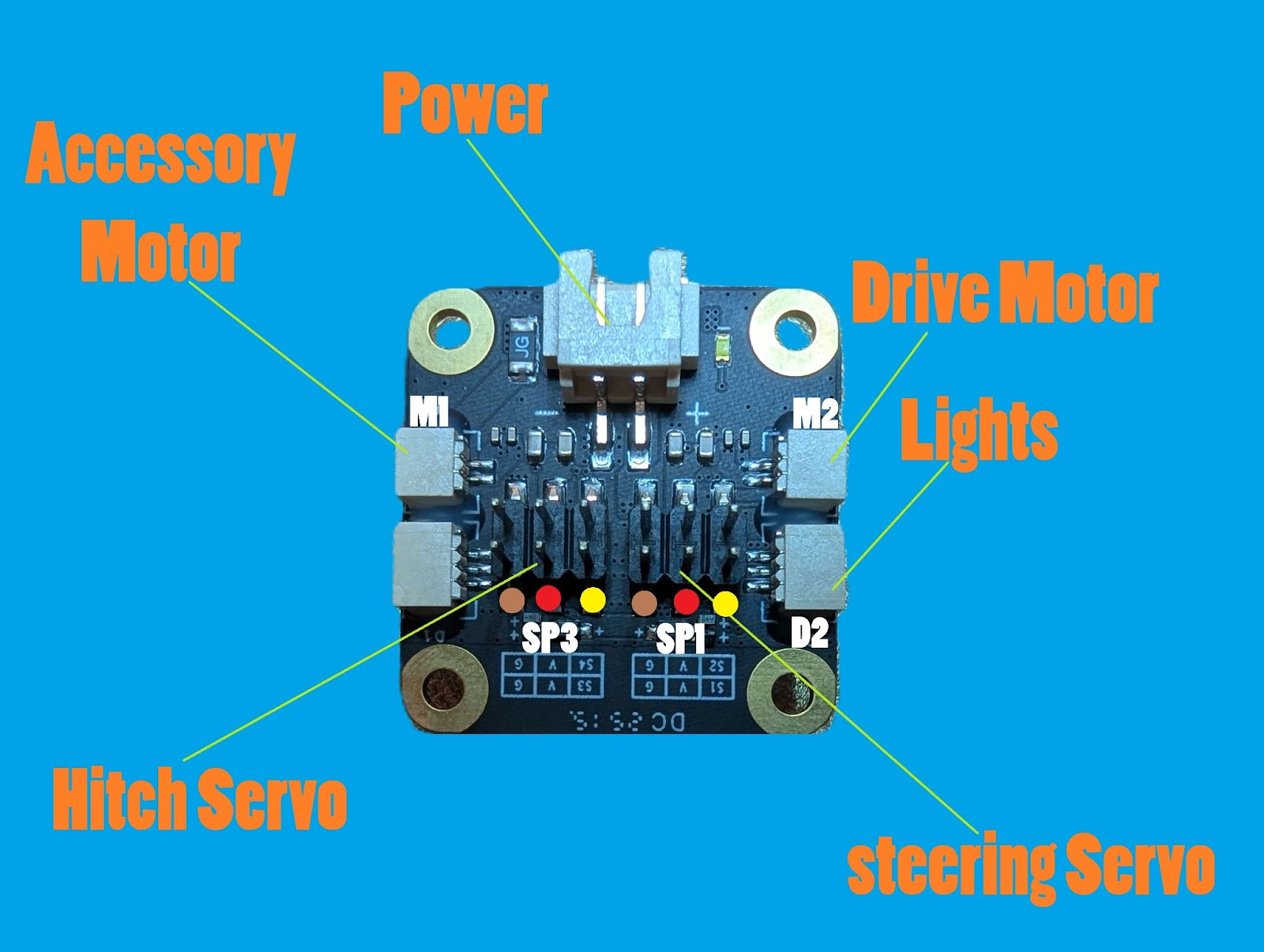
Configuration
Step 1. With no motors, servos, or lights connected power on your remote and receiver. Use battery or USB
Step 2. If you don't have your remote and receiver connected in your cyber brick app connect them. You can do this in the Devices Tab
Step 3. Find the project on the app and select the .json Config File that works with your controller. Users can make a custom config for other controllers or request them in the comments.
Step 4. Follow in app steps to save config to remote and receiver
Servo alignment
Step #1. Loosen the screws on both servos
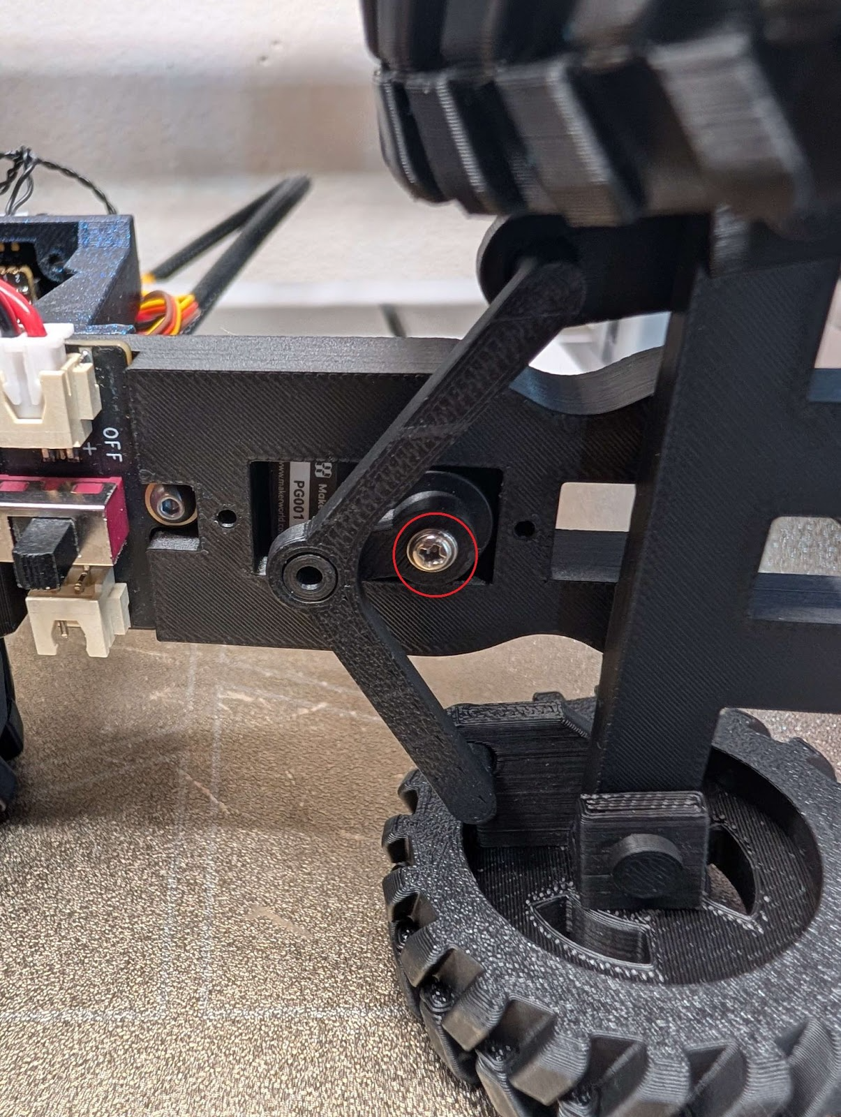
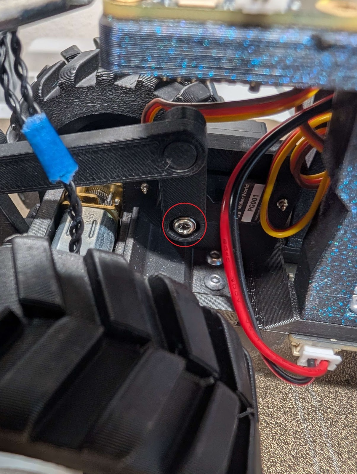
Step 2. Temporary connect both servos to the receiver. Use the Receiver Diagram above.
Step 3. Power on the remote and receiver. The servos should move home. You will have to temporarily remove the li-po in the body to power the receiver.
Step 4. Move your front wheel until they are strait and then tighten the servo screw.
Step 5. With the 3 point switch that controls your hitch at position 0, rotate your hitch until it’s level with the frame. Then tighten the servo screw.
Step 6. If you used the battery in the body you can reinstall it.
Lights
Step #1
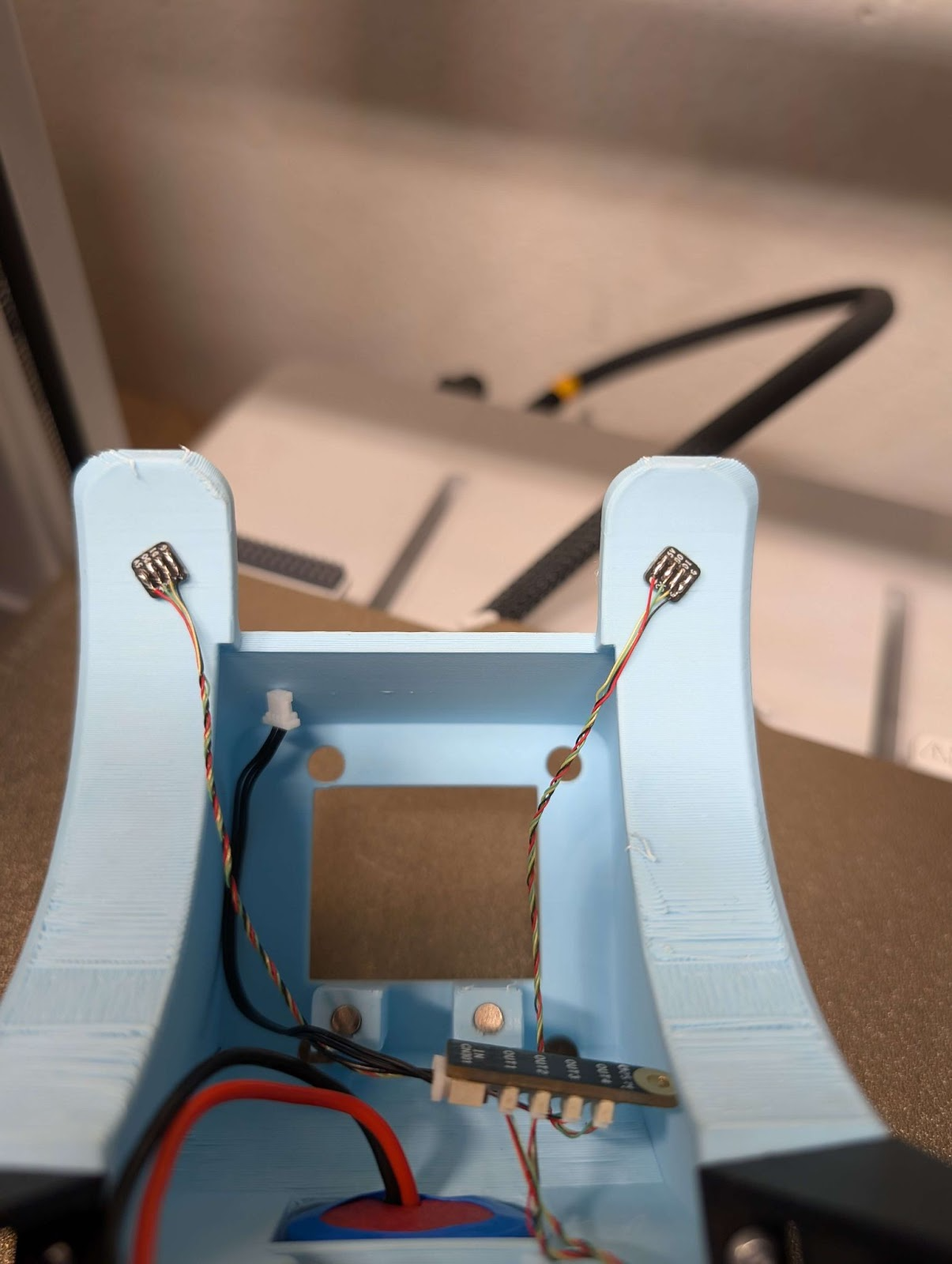
Press the 4 lights into the controller board slots. Then, use lights in slots 3 and 4 and press them in to back fenders
Step 2.
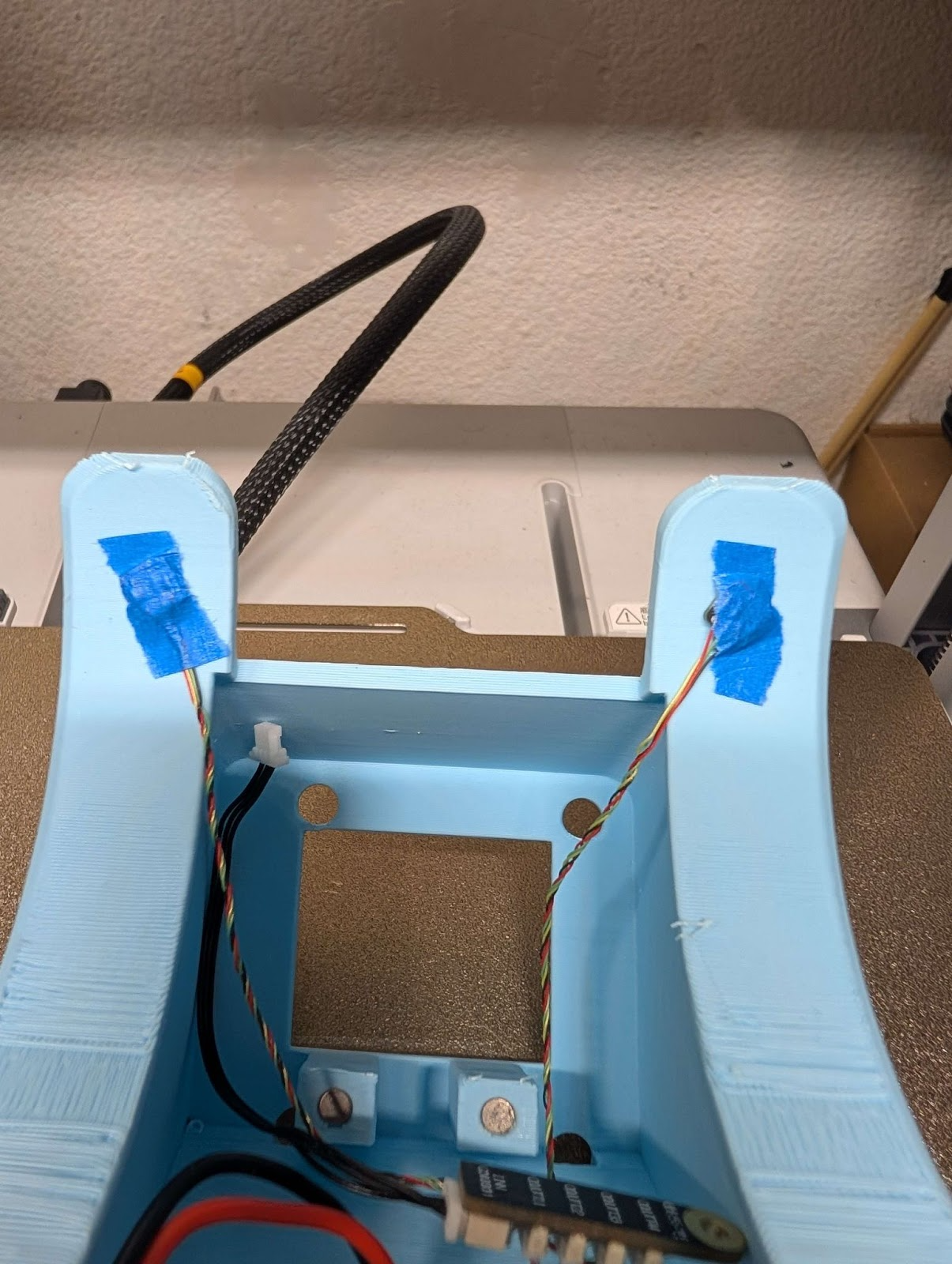
Tape or use hot glue to secure lights.
Step 3.
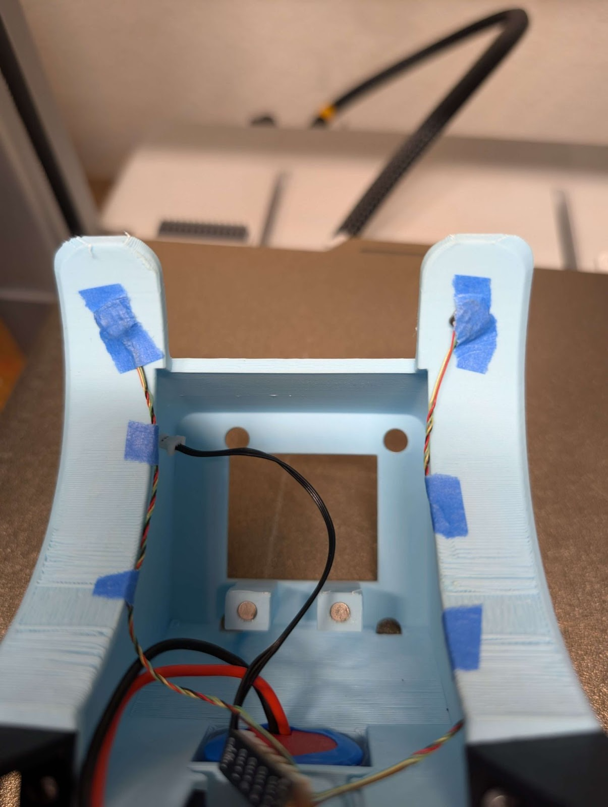
Tape or hot glue to wires to the inside of the fender to get them out of the way.
Step 4.
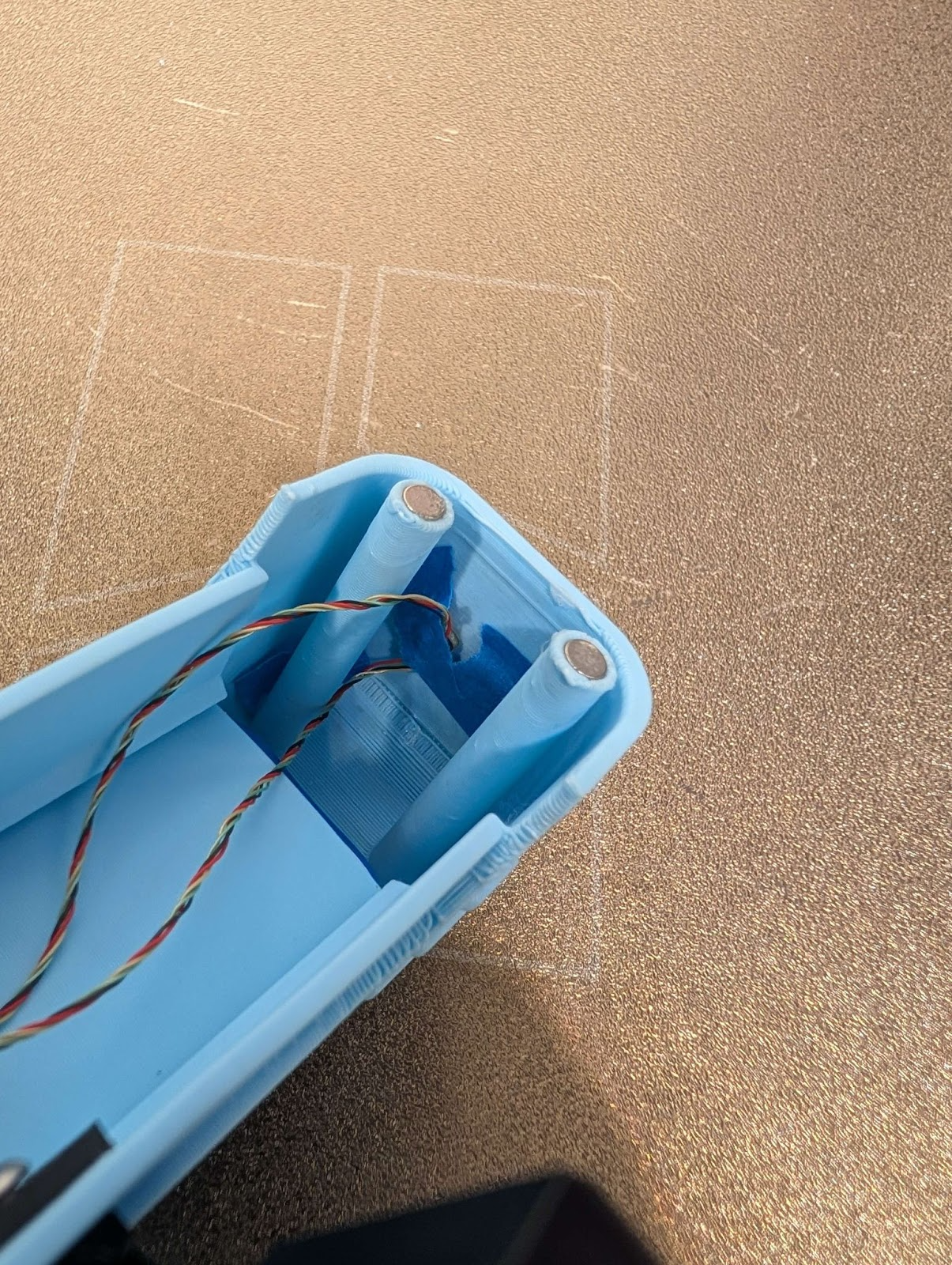
Press lights in slots 1 and 2 into the front light position. Use tape or hot glue to secure them.
Step 5.
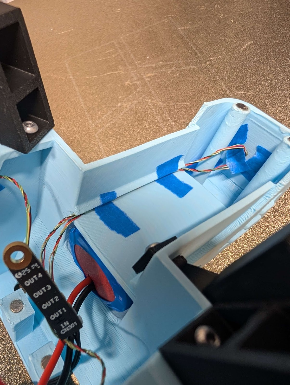
Slide the wire in the gap on the body and use tape or hot glue to secure it.
Final Construction
Step 1.
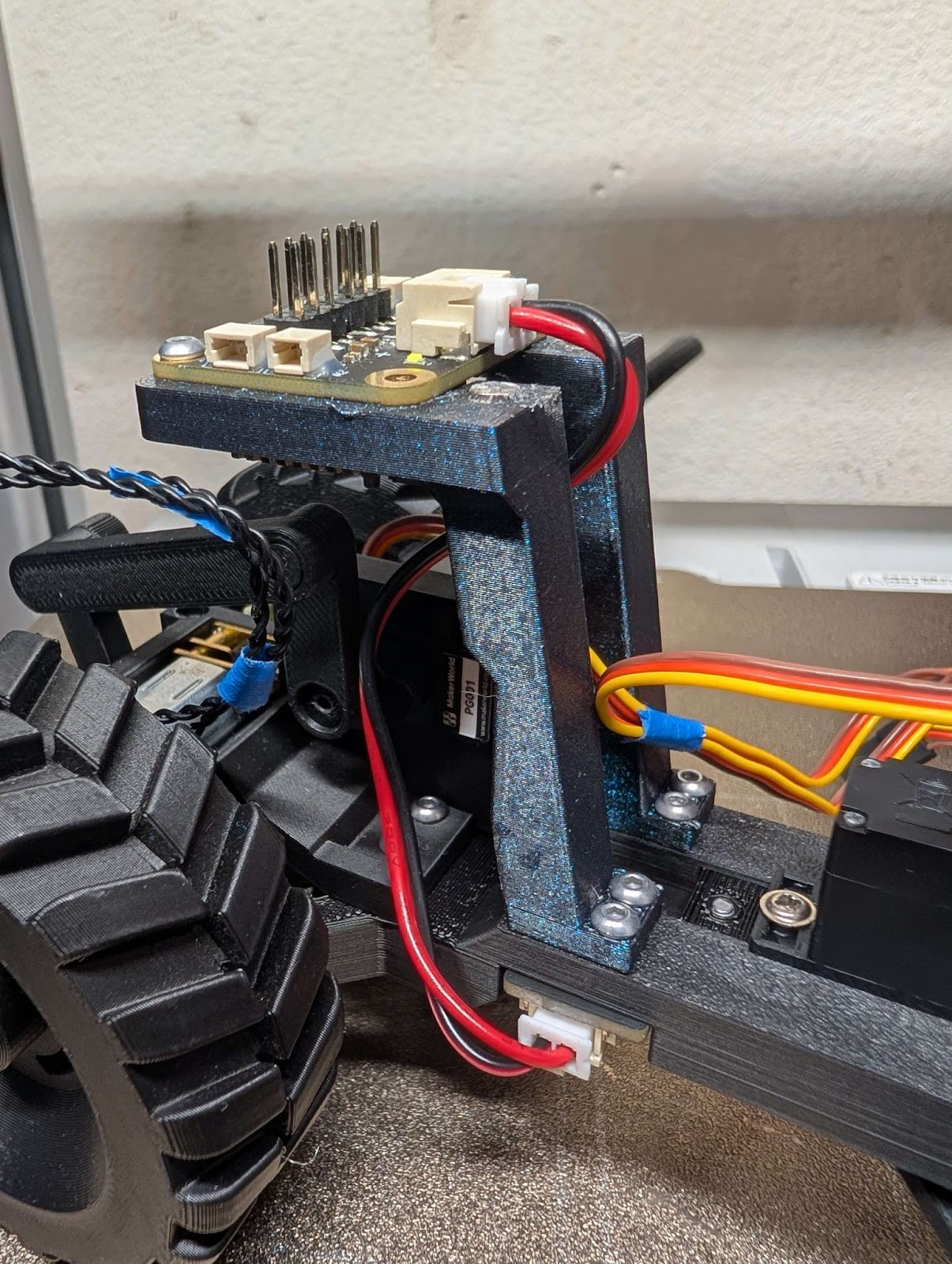
Connect the wire that came with the switch to the switch and the power in on the receiver.
Step 2.(optional)
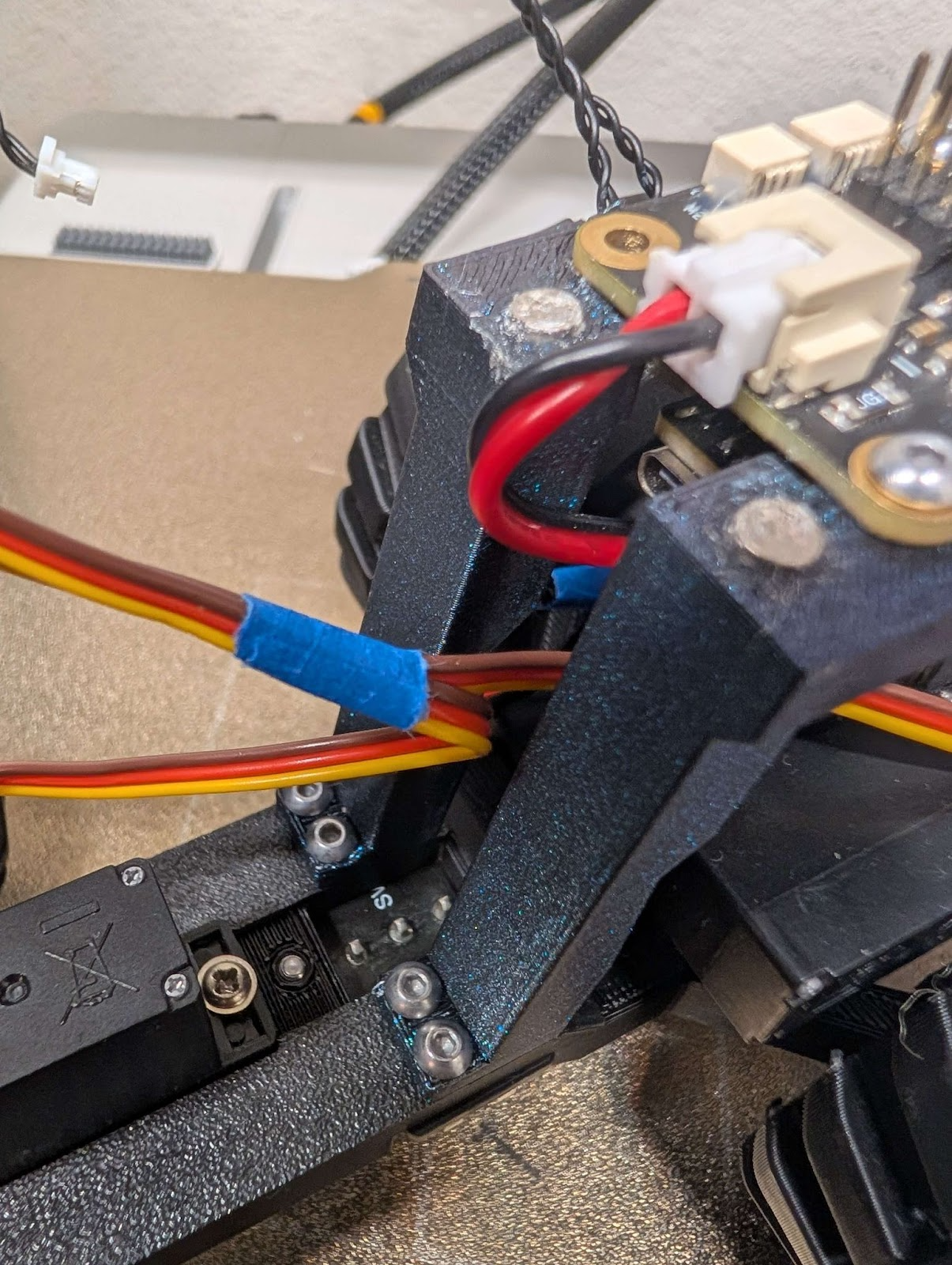
Tape the two servo cables together close to the bottom.
Wire management
Step 3.(optional)
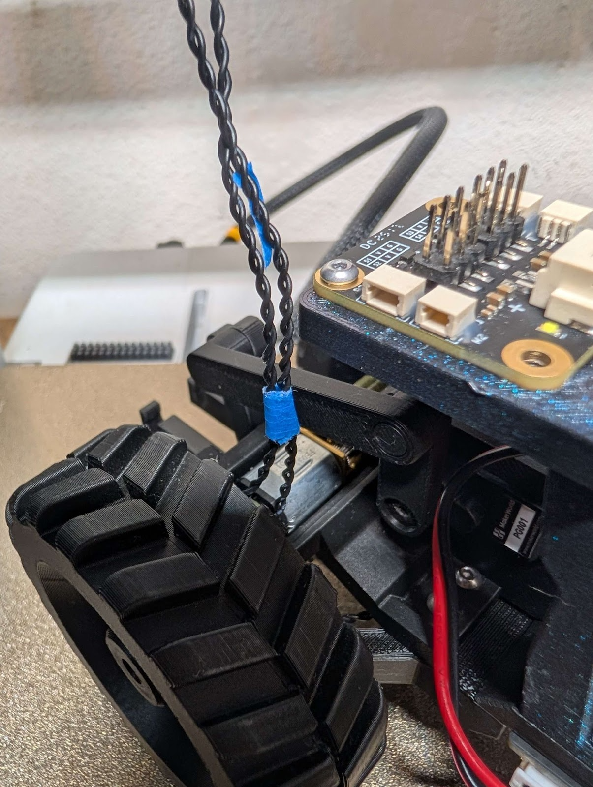
Tape the two motor cables together close to the bottom.
Wire management
Step 4.
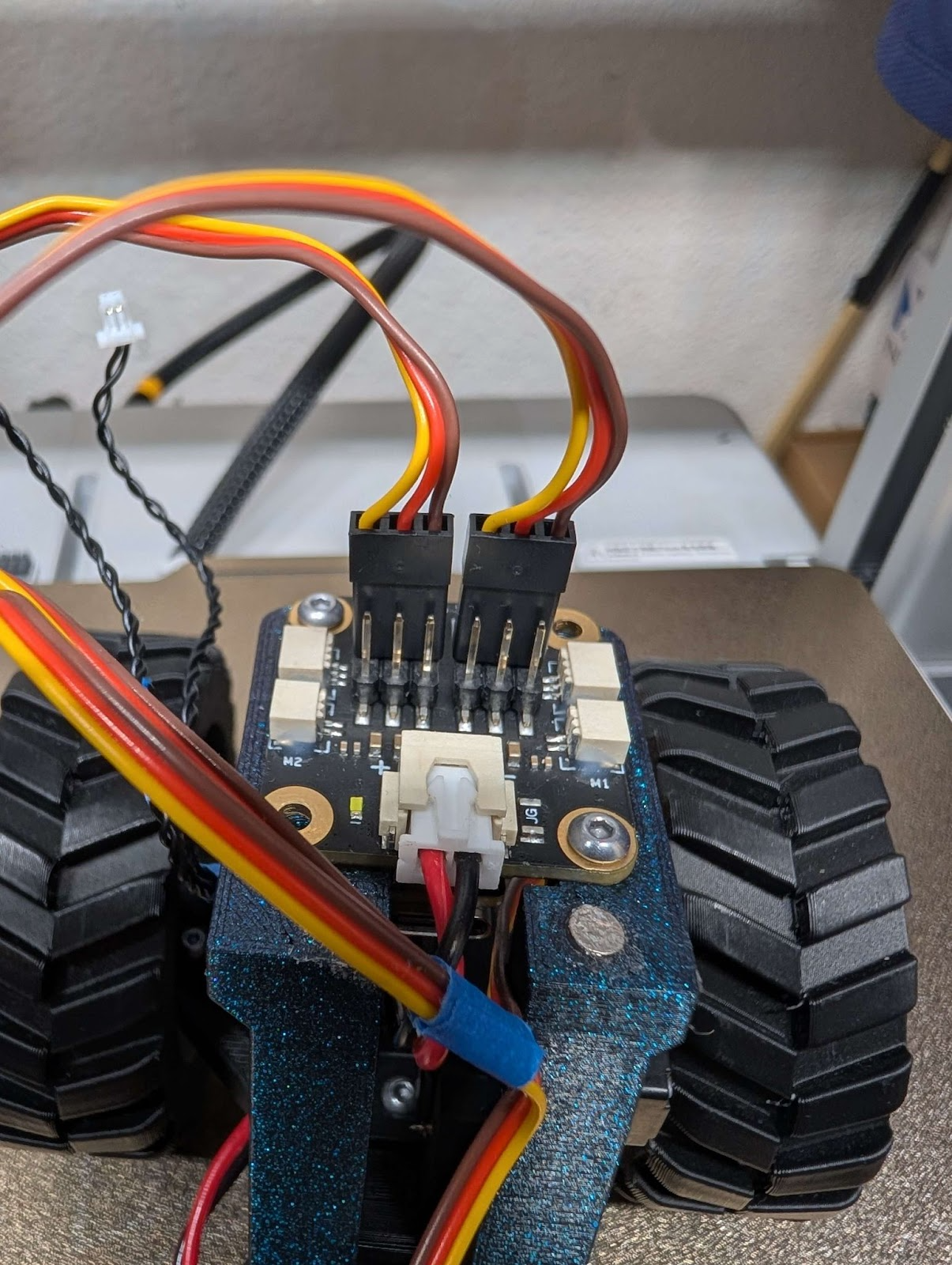
Using the receiver diagram above connect the two servos to the receiver.
Step 5.
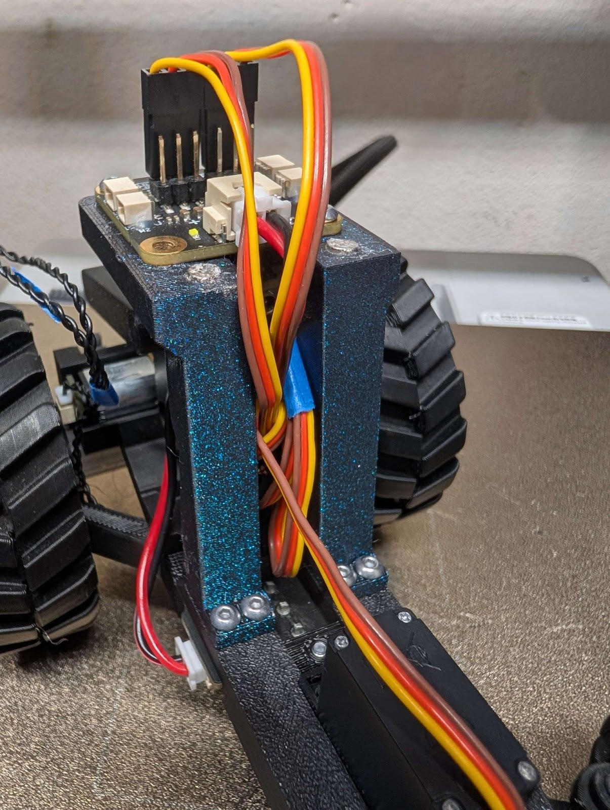
Tuck excess wire in the middle of the body mount. Wires should not go over the magnets.
Step 6.
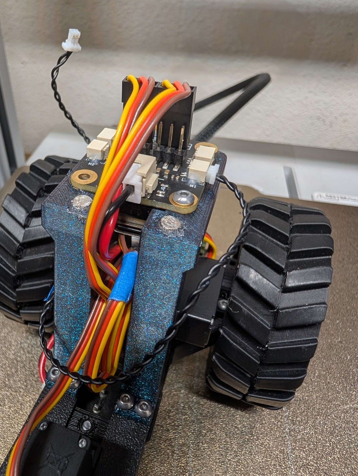
Using the receiver diagram above connect the Accessory Motor to the receiver connector M1.
Step 7.
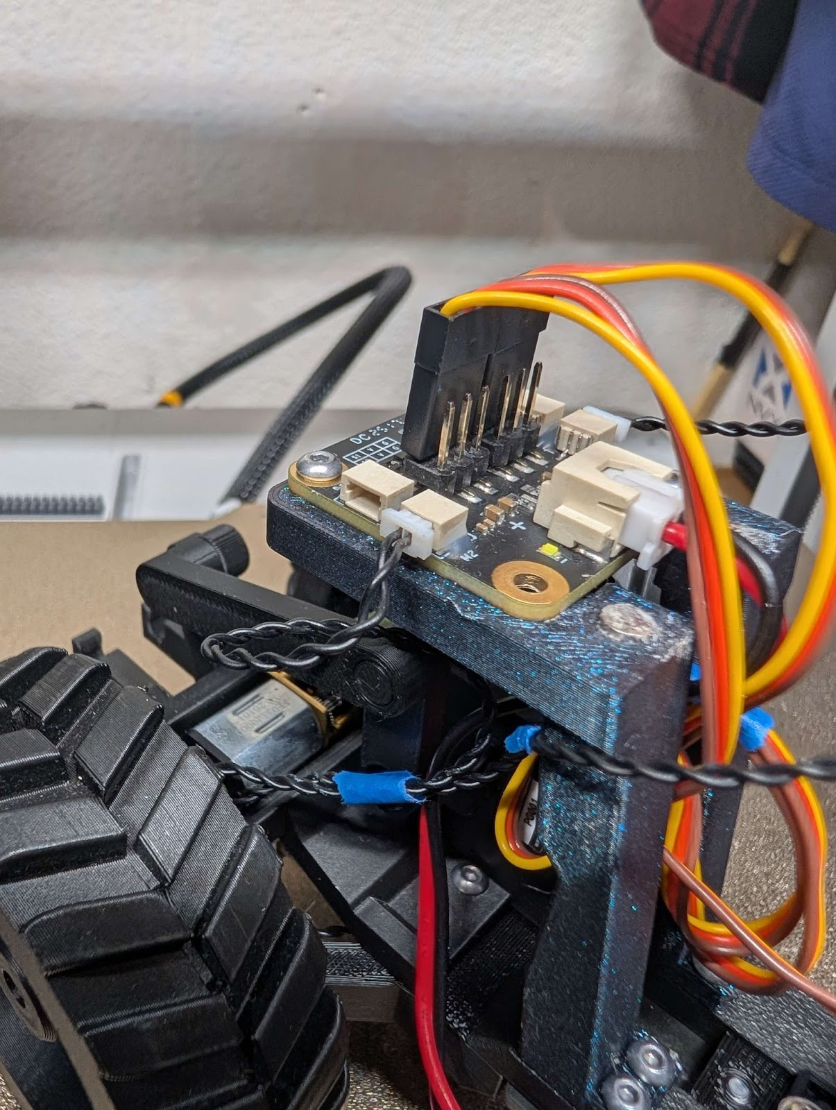
Using the receiver diagram above connect the Drive Motor to the receiver connector M2.
Step 8.
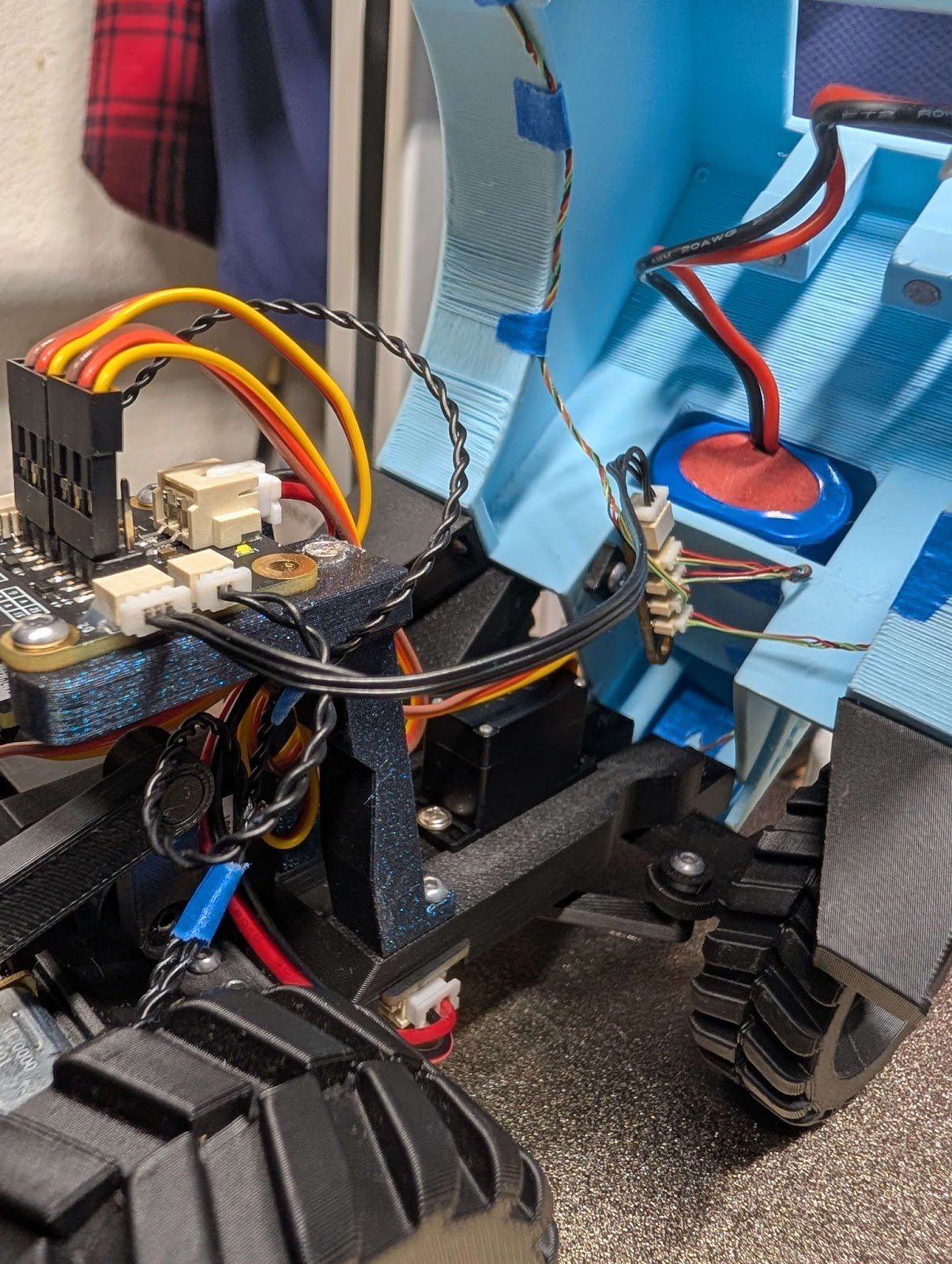
Prop the body of the tractor up on the frame and use the receiver diagram to connect the RGB controller to the receiver slot D2.
Step 9.
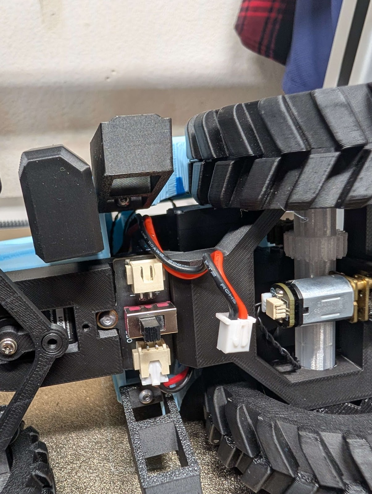
Lower the body on to the frame while keeping the power cable from the battery on the empty side of the switch
Step 10.
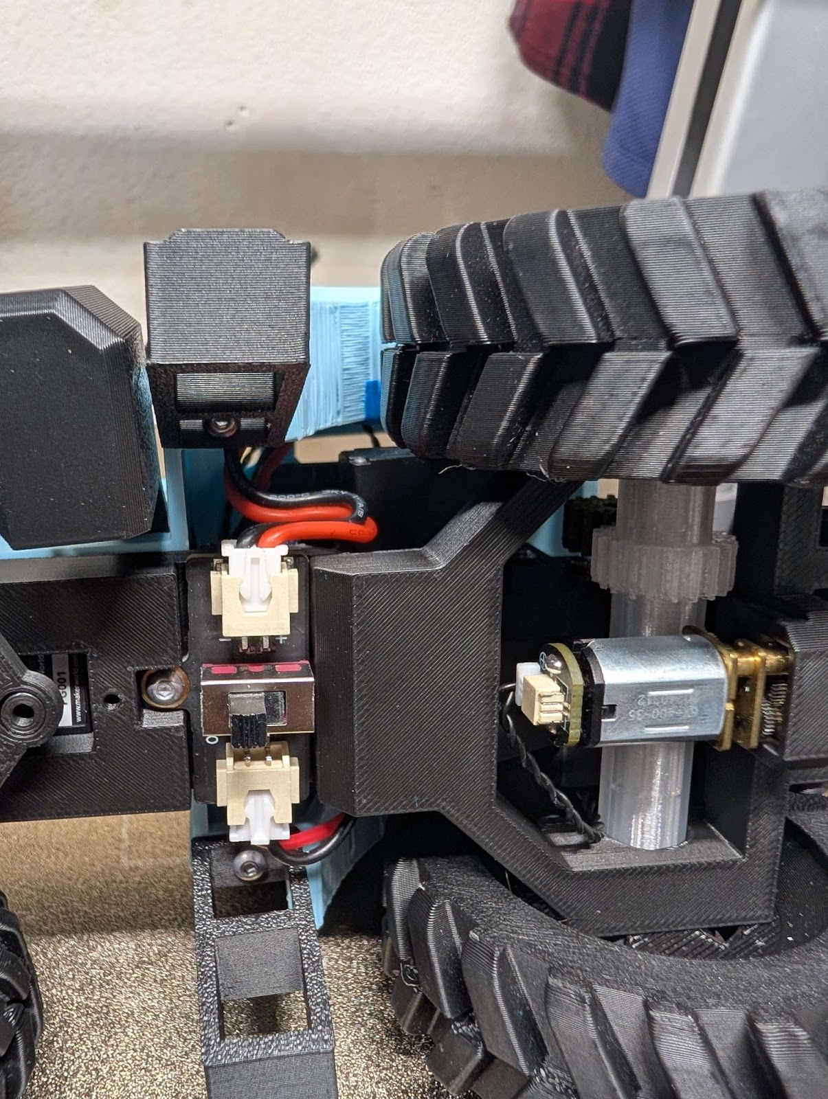
Plug the battery into the switch
Finished
Plow instructions
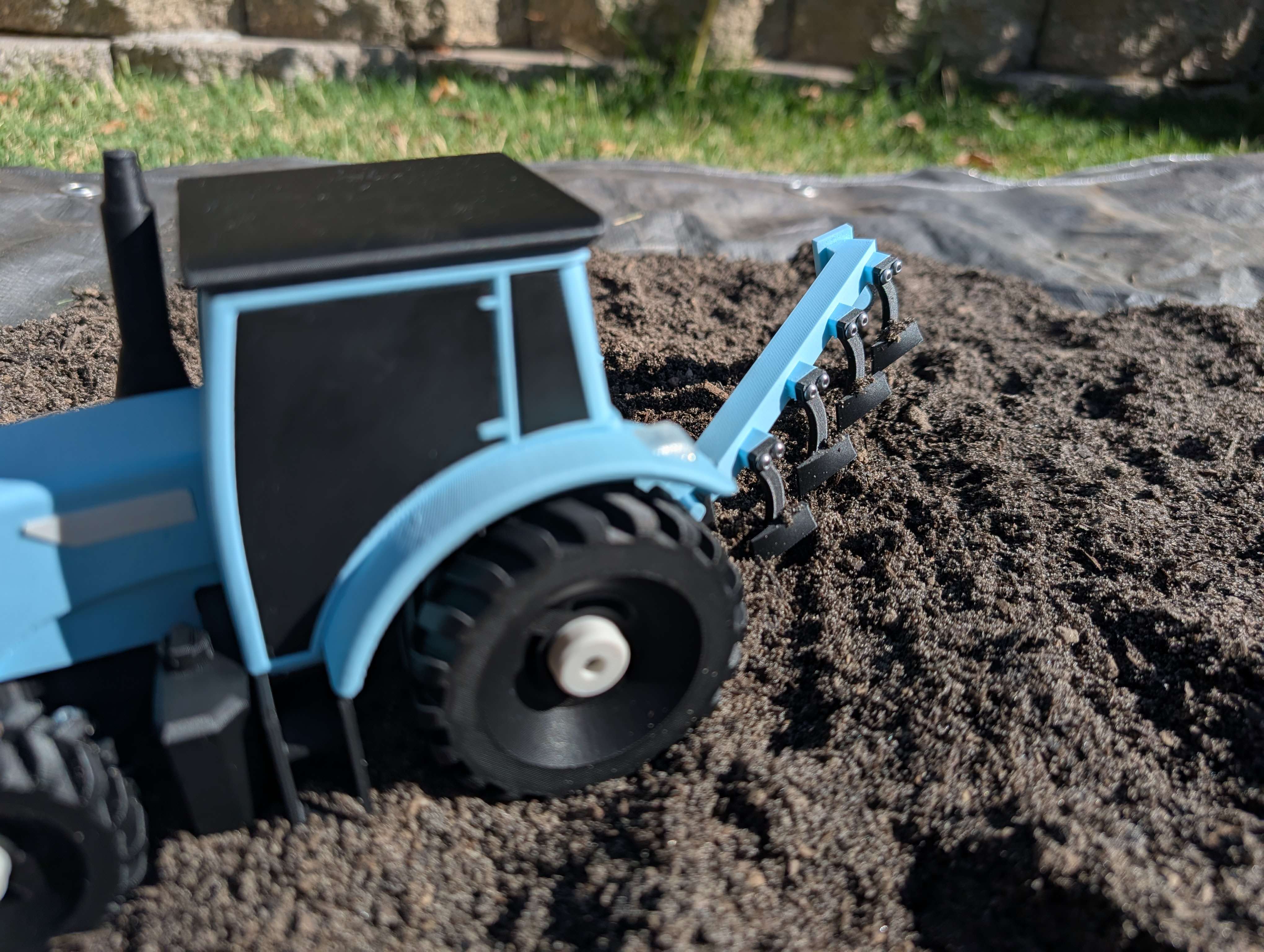
First of many attachments.
Step #1
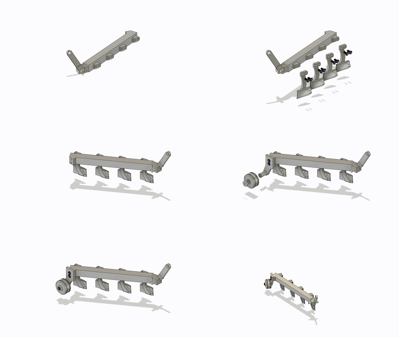
Step #2
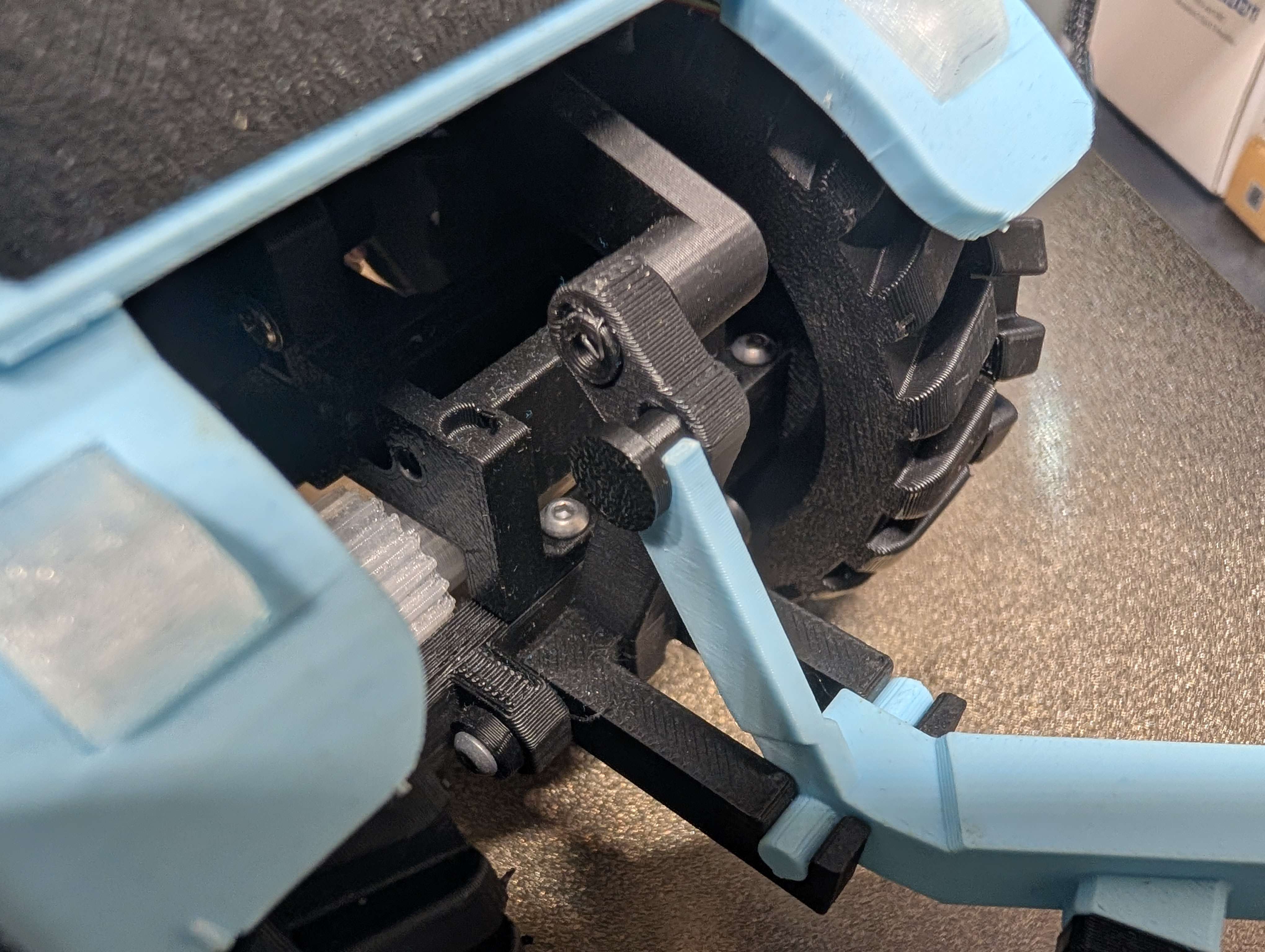
The bottom of the plow clips in the hitch and a pin keeps the top in.
Thanks for Printing
(Attachments will be released over the next few months)

Gostou deste modelo? Crie uma conta grátis para salvar seus favoritos e voltar a eles depois.
Criar conta