There was something magical about arcades growing up. The flashing lights, the chaotic sounds, the clatter of tokens, and of course, the pinball machines. For me, pinball was always the heart of the arcade. I could spend hours watching the ball bounce between bumpers and sliding down curved ramps.
I wanted to capture the spirit of a classic pinball machine in a form small enough to fit on a desk, but still packed with character. I also prioritised the aesthetics, designing it to look and feel like a proper mini arcade machine. What makes this design stand out is its unique use of tubes that guide the ball around the playfield, even beyond the main body.
Parts Needed
20 mm rubber bands – Used for the flippers and launcher mechanism. These can be easily sourced, and I recommend the affordable 20 mm rubber bands available from Bambu Lab’s Maker Supply.
If you already have it, the Maker's Beginner Kit also contains the rubberbands and ball bearings.
8 mm steel or plastic ball bearings – These serve as the pinballs. I used steel as they were lying around. I have not tested this with any other sizes of ball bearing.
Print Settings
Material:
PLA recommended. I printed most of the model with PLA Matte, but there are a few parts that need to be printed in PLA Basic for better layer adhesion (details available in assembly instructions)
TPU feet are included in the files, but it's not required.
Print Bed Size: All parts fit on a standard 256 x 256 mm bed (A1 and up)
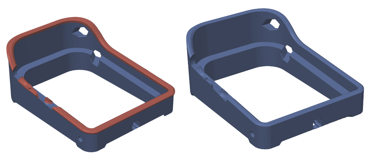
There are 2 print profiles provided, one for the H2D and one for single nozzle printers.
The main body in the H2D profile has an accent colour, while the single nozzle profile does not due to high filament wastage.
Left: H2D | Right: Single Nozzle
Assembly
PLEASE DRY FIT ALL PARTS BEFORE GLUING.
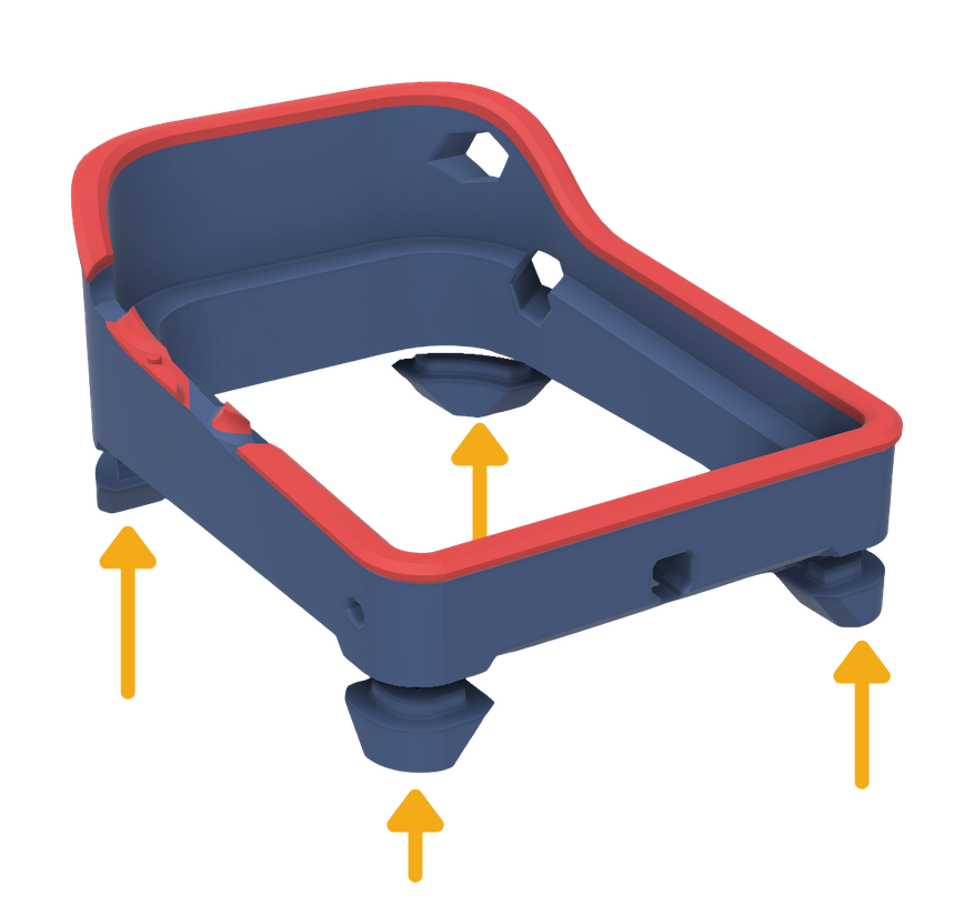
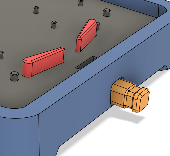
Attach the feet to the main body.
Hold it firmly when gluing to minimize seams.
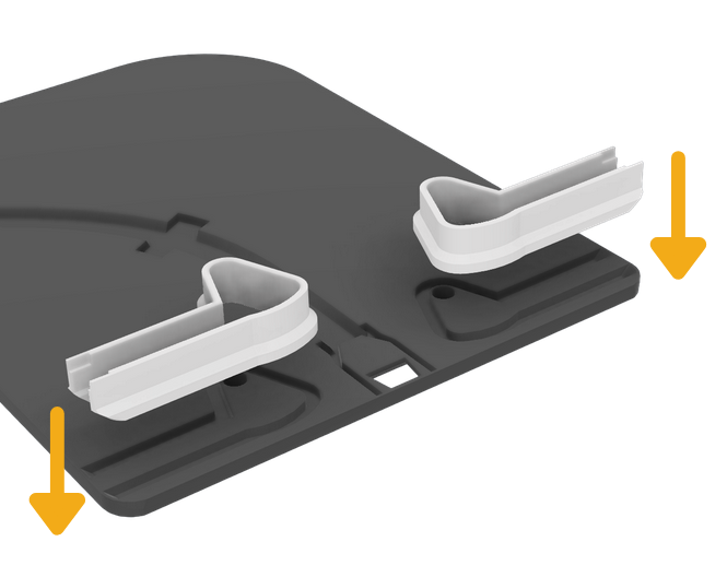
Attach the push mechanism casing to the board.
Use the inset grooves in the board to align and glue the parts together.
Do not use PLA Matte / Silk for this as they break easily. This part needs good layer adhesion.
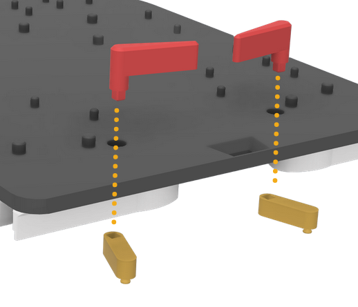
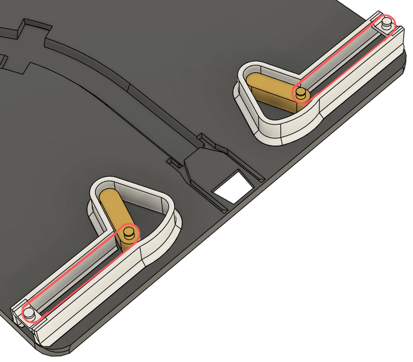
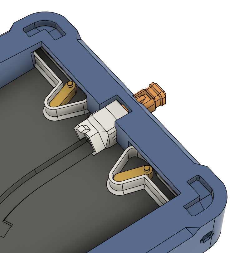
Push the extended pins of the flipper through the board, and glue the levers at the other end.
The second image shows how they should connect together, and the board is hidden for clarity.
Do not use PLA Matte / Silk for the levers (yellow parts) as they break easily. This part needs good layer adhesion.
After gluing, keep moving the flippers while the glue dries, to ensure that the parts do not stick to the board.
ENSURE THAT THE SQUARE PINS LINE UP, AND THAT THEY ARE CONNECTED AT THE ANGLE SHOWN.
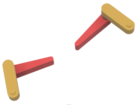
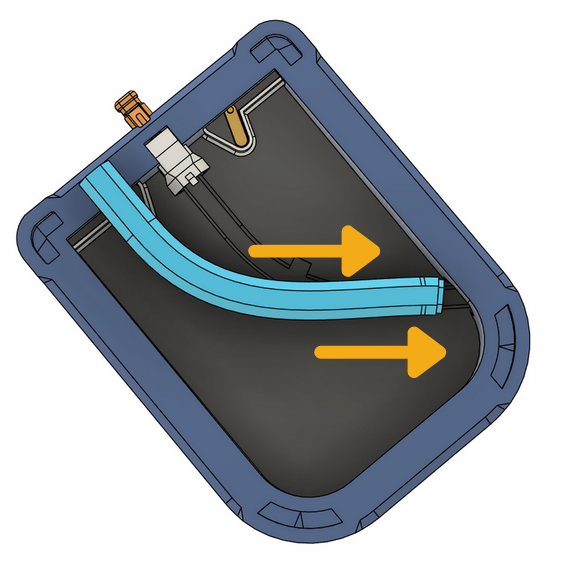
Attach a 20mm rubberband to each of the protruding points on both sides, as shown in the crudely drawn diagram ;-;
This should cause the lever (yellow part) to always bounce back towards the side.
Place the ball collector and launcher in their indent, but do not glue them in yet as you may have to adjust the rubberbands.
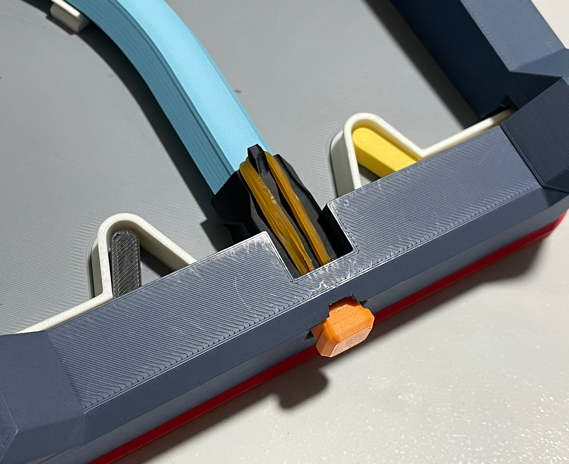
Place 3-4 20mm rubberbands stretched between the parts as shown. Each band does not have much elastic power, so multiple is needed to allow the ball to reach the top of the return tube.
I used 3, as any less was not able to consistently make the ball reach the top of the tube for me
You don't have to, but I added a drop of superglue on each end where the rubberbands and plastic parts met so that they wouldn't come out during use. It makes it a lot more convenient.
When you pull on the launcher, it should be pulled back by the multiple rubberbands with some force.
The two parts (Ball collector and launcher) might have some roughness when moving across each other at first, but after a while it should wear down enough to move smoothly.
Place the whole board in the main Body.
I do not recommend gluing the board into the body as it makes maintenance/troubleshooting a lot more difficult.
We did not glue the ball collector & launcher beforehand as you will have to maneuver it through the hole in front to get the board in.
Do not glue it in yet until everthing is confirmed to be working.
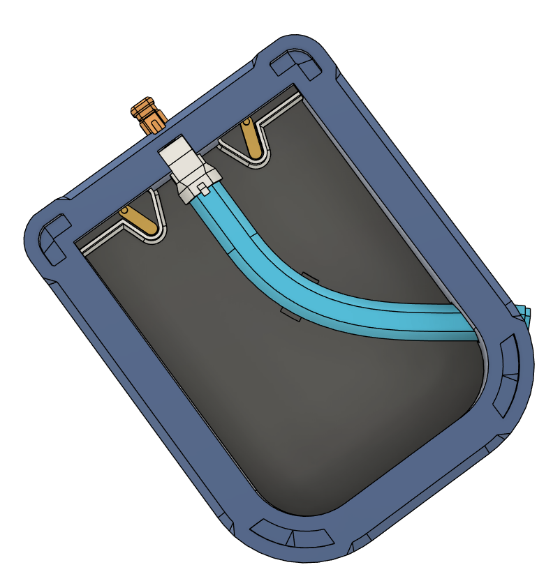
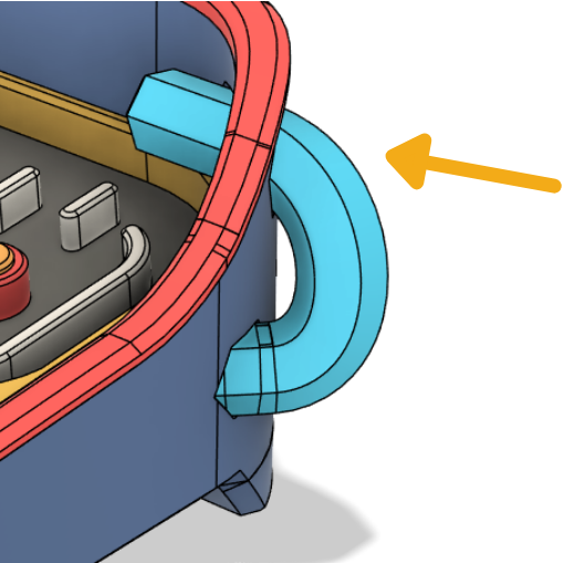
Push one end of the tube through the bottom hole in the main body.
It might be hard to push it through at first, but once you angle it correctly it should slide in smoothly
The side facing the outside should have a connection protrusion, while the other end should just be flat.
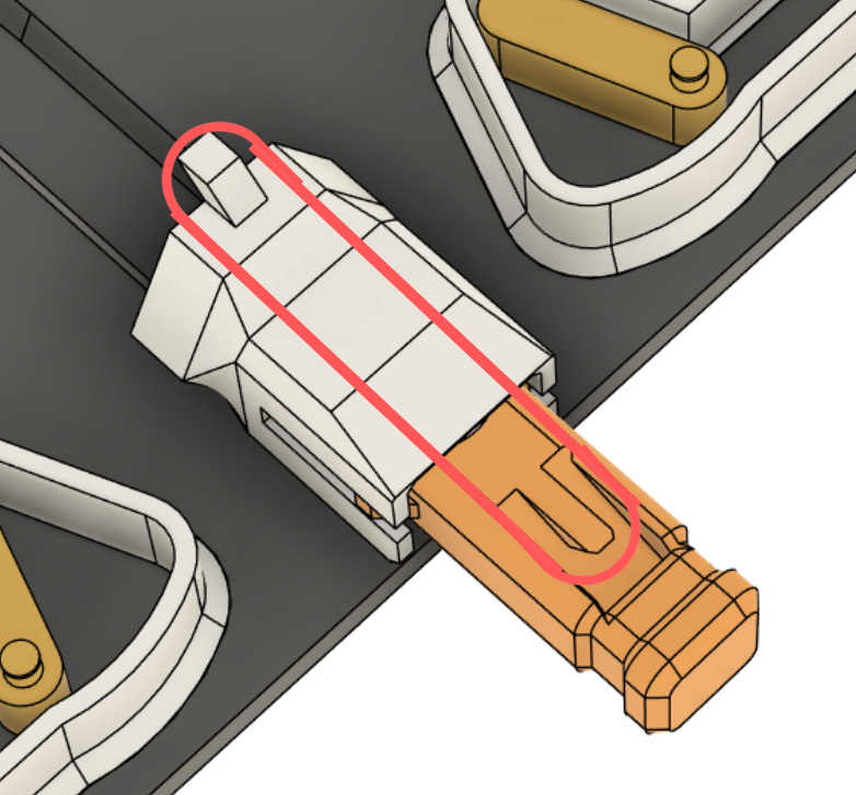
Connect the flat end to the ball collector (shown in white).
Once everything is aligned properly, glue the ball collector to the board, aligning it with the respective indent
The ball collector and the hole should support the tube enough that you do not need to glue it.
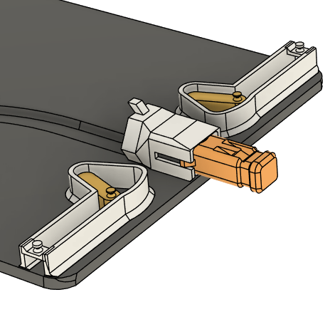
The third image is what it should look like thus far.
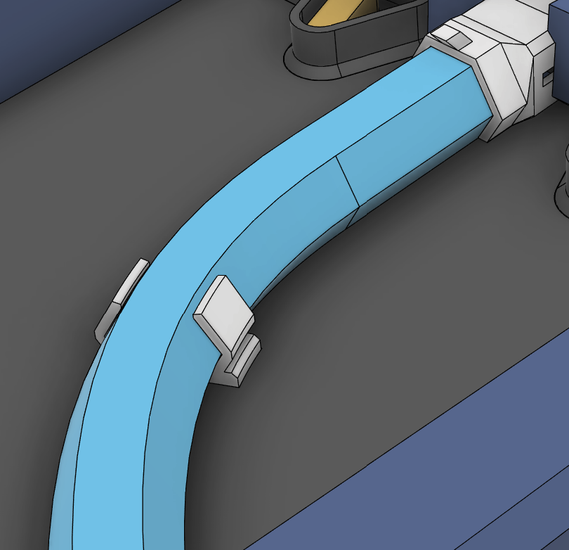
To lock the tube in place, attach the 2 support pieces on either side of the tube.
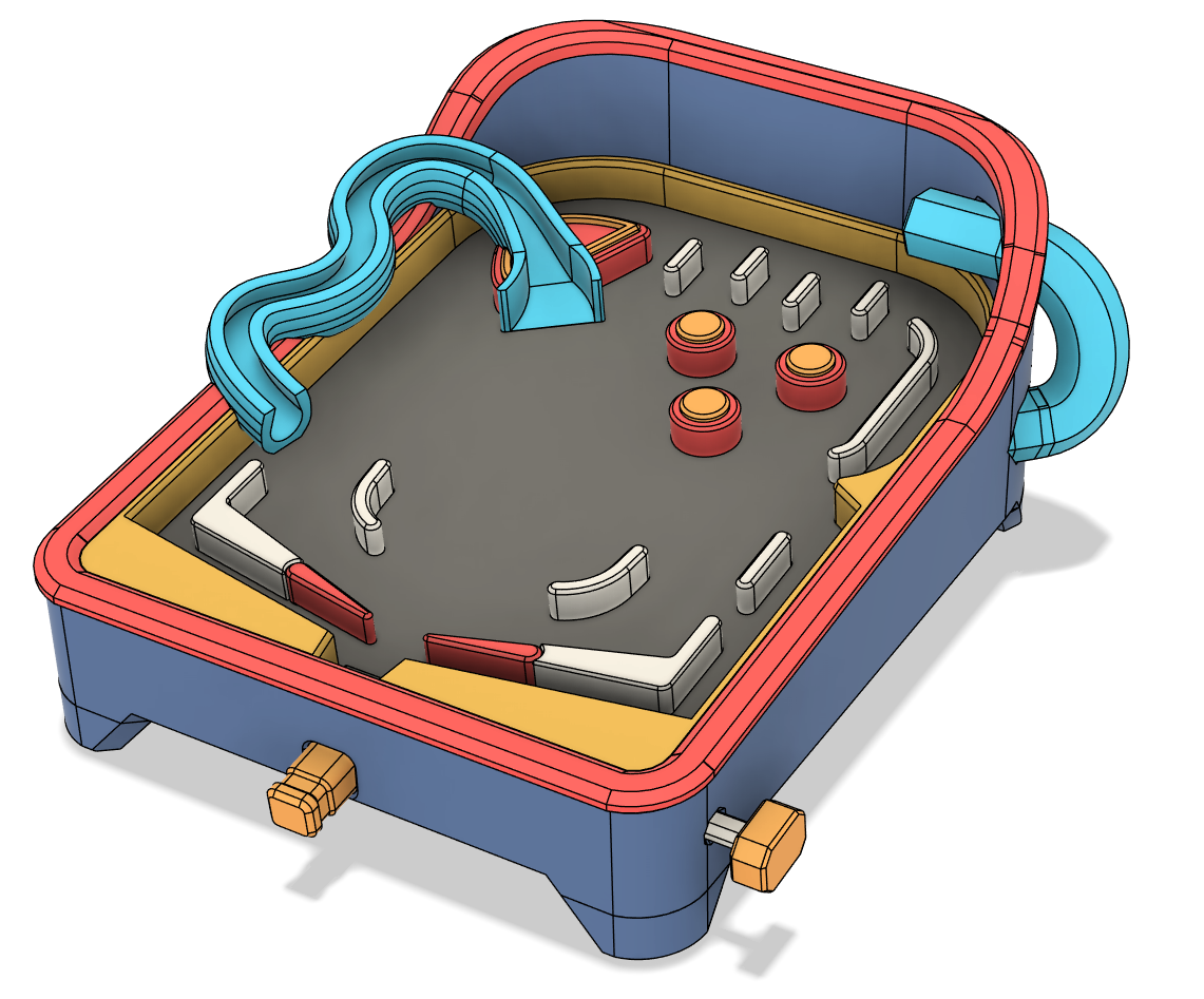
Attach the pinball layout parts to the board.
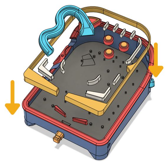
The items have holes that line up with the pins in the board, except the frame (yellow border)
This is because the frame aligns itself against the walls of the main body and does not need additional pins for alighment.
Ensure that you attach the frame before the ramp (blue item)!
Before gluing the ramp entrance down, ensure that it is flush with the rest of the board. Trust me, it's already hard enough to hit that ramp. You don't want to make it harder.
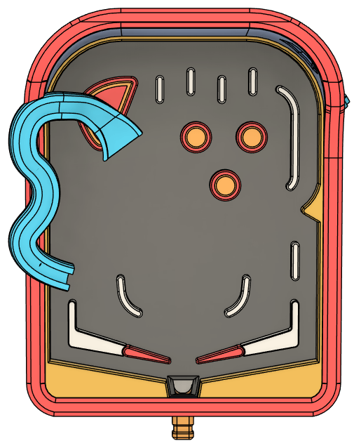
Use the second image as reference of the board layout.
Optionally but highly recommended:
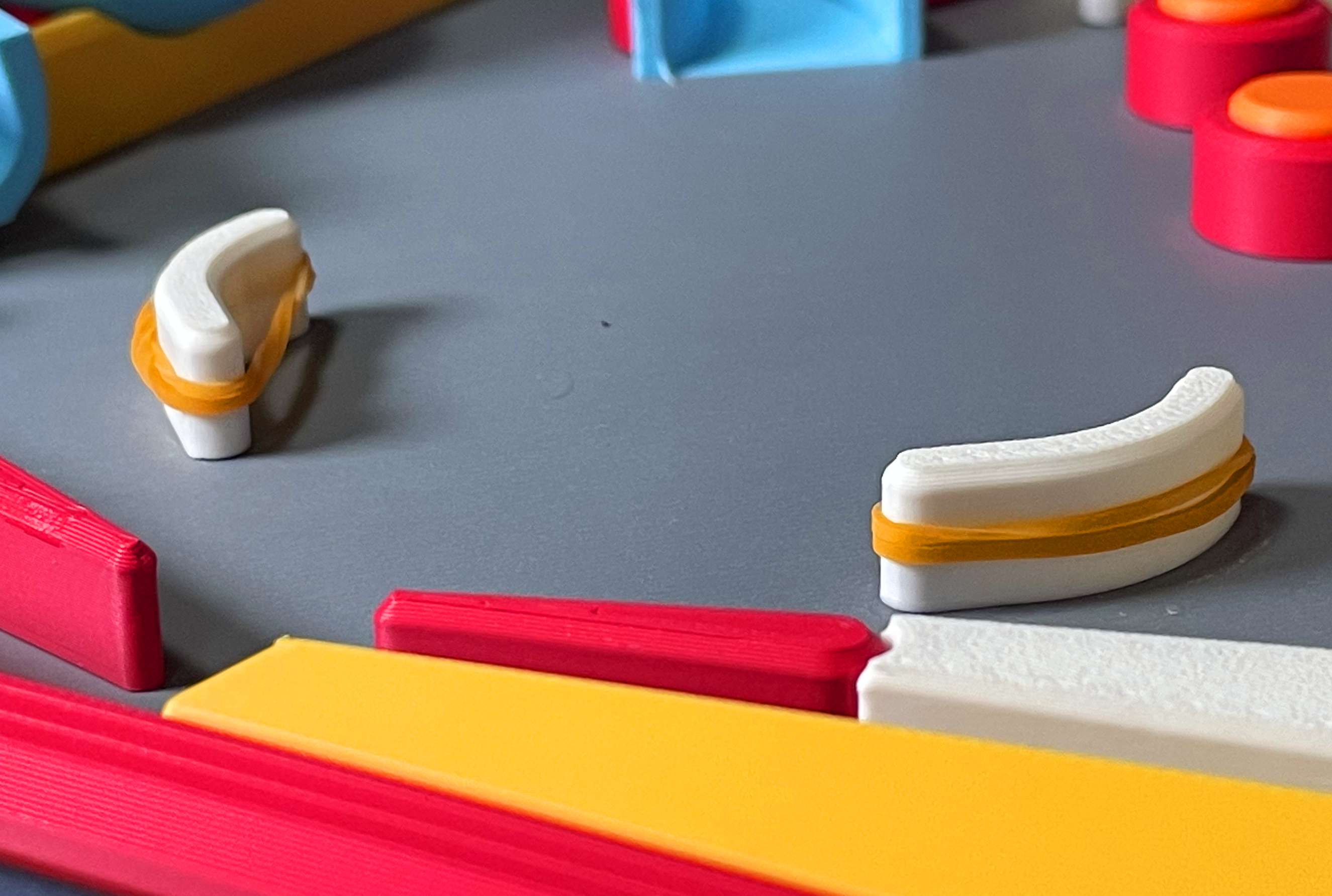
You can double twist a rubber band and wrap it around the Slingshots (Center curved pieces) such that it is taut.
This allows the ball to bounce off the item instead of just hitting it and sliding down.
Slide in the second part of the tube, and attach it to the first by applying some glue at the connection points.
Before gluing, hold the tubes together and use a ball to test if the launcher works.
Check if the sliding movement between the launcher and the ball collector is smooth or abrupt.
If the launcher works but it just does not have enough power to send the ball all the way up, check that you have enough bands.
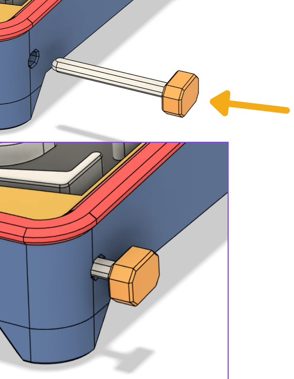
Insert the trigger. It should go in all the way without obstructions.
If the hole is obstructed, your board is likely not flat against the body.
When the trigger is pushed, the flipper should rotate upwards.
The pinball machine should be completed!
This model is a lot more complicated than my past projects, so do let me know if any of the instructions are unclear to you.
If you have any issues with assembly do leave a comment.