Você está no 3DFinder
Buscamos em Thingiverse, MakerWorld e Printables ao mesmo tempo para te dar o melhor de cada uma.
Descrição
🕹️ Introduction
I’m an arcade gaming enthusiast and have long wanted to create a compact, custom controller that could deliver the same feel as old-school arcade machines but in a USB plug & play format.
For this reason, I decided to design a gamepad based on the Arduino Pro Micro, with a 3D printed case and customizable button mapping. The goal was to create something easy to replicate but also simple to modify—perfect for DIY lovers.
This project also connects to two other controllers I built in the past:
👉 Joypad for arcade with keyboard keys – a compact arcade-style layout
👉 Arcade button for keyboard keys – custom buttons designed for mechanical keyboards
🧾 Bill of Materials (BoM)
| Quantity | Component | Description |
|---|---|---|
| 1 | Arduino Pro Micro | HID-compatible microcontroller with USB-C or micro USB connection |
| 11 | Mechanical switches | Keyboard-style switches (e.g., Cherry MX, Gateron, etc.) |
| 1 | Perfboard | 60mm x 40mm |
| — | Copper wires | Any type suitable for soldering |
| 4 | Buttons | Link to buttons |
| — | Male pin headers | For modular wiring |
| — | Female pin headers | For connection to the Arduino PCB |
🔧 Soldering and Wiring
This project requires good soldering skills, especially if you want reliable and clean connections. Personally, I preferred a method that allows easy disconnection of each button for repairs or modifications:
- I soldered a male pin header to each wire (jumper-style strips).
- On the PCB (Arduino Pro Micro) I soldered a strip of female pin headers so I can plug and unplug wires individually without resoldering everything.
This approach has two advantages:
- It prevents stress on the PCB from repeated soldering and desoldering.
- If a button stops working, you can easily test or replace the single wire.
Of course, if you want to save space or have a more stable wiring, you can solder wires directly to the board. For me, modularity was a priority.
💡 Tip: Use good quality solder and avoid excessive amounts. A small mistake here can cause false contacts or hard-to-diagnose shorts.
🧠 Button wiring scheme
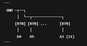
You can find the code in the Documentation section.
🎮 How to test the gamepad on Windows
To make sure the gamepad is recognized and each button responds correctly, you can use Windows’ built-in tool for testing HID devices:
Steps to access the test:
- Press Windows + R on your keyboard
- Type joy.cpl and hit Enter
- The Game Controllers window will open
- Select your device (e.g., “Arduino Leonardo” or your custom name)
- Click Properties
- Go to the Test tab to try each button
💡 Note: If your mapping emulates keyboard keys (HID that sends W, A, B etc.), this window won’t show button presses. In that case, test buttons by opening a text editor or using a site like KeyboardTester.com.
🎨 Customizing the top cover
To facilitate customization, I included the F3D (Fusion 360) file of the top cover.
This allows you to freely change the button layout or add drawings, logos, or color decorations directly in the 3D model—for example, to create different versions.
⚠️ Important: Do not modify the size or proportions of the top cover, as these are optimized to fit perfectly with the rest of the case and the button/pin positions.
💡 Tip: You can also use the F3D file to sculpt personalized graphics or separate surfaces for multi-color printing by layers.
📢 Conclusion and Call to Action
I hope this project has inspired you to build your own custom gamepad! If you decide to take on the build, don’t hesitate to share your progress in the comments or on social media—I’d love to see your versions, mods, and ideas.
Feel free to suggest improvements or new features, and of course, if you have any questions, I’m here to help!