Você está no 3DFinder
Buscamos em Thingiverse, MakerWorld e Printables ao mesmo tempo para te dar o melhor de cada uma.
Descrição
Summary
Do you have to reach under your desk to turn-on your desktop computer? You need this button!
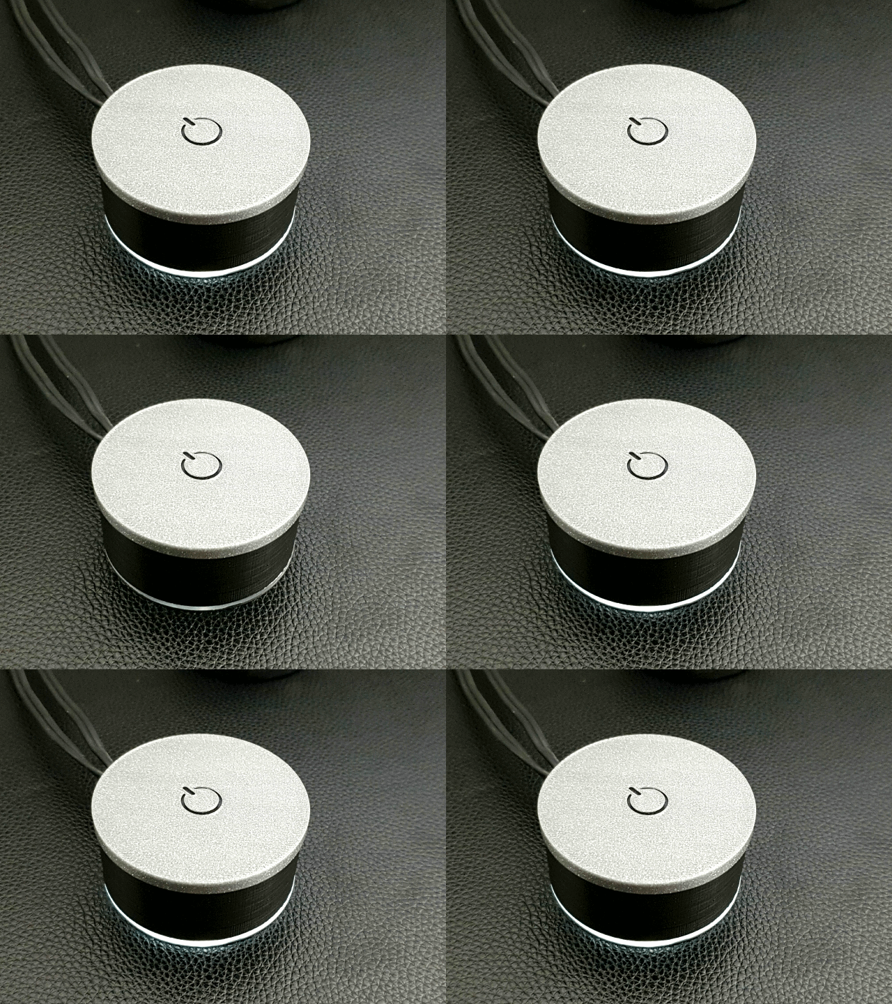
This cool looking button with interchangeable top cover with breathing lighting effect has been designed to be cheap, easy to print, easy to assemble and easy to upgrade.
Project Difficulty: Easy
Total Print Time: ~1 Hours
Total Project Built Time: ~3 Hours
You have two options:
1)Connect the LED through Arduino (recommended)
This gives you the breathing effect and enables future updates
2)Connect the LED directly to the motherboard
Follow the project for future modifications/upgrades
How it Works?
The 3D printed button can be placed anywhere on your desk where it is convenient for you to reach. It can turn your computer on and off (or hibernate/stand-by depending on the settings on your windows). There is an LED inside the button which illuminates around the button with a breathing effect while your computer is on.
Planned upgrades (depending on your response and support):
-Add Bluetooth module to wirelessly turn on the PC
-Turn on your PC with your voice (Google Home)
-Upgrade the LED to RGB
-Adding other functions?
If you have any questions/suggestions please write it in the comment section.
Cheers!
Disclaimer:
I am not responsible for burned motherboards! Please proceed only if you have basic hardware knowledge!
What You Need
Skills
-Program the Arduino (no coding needed)
-Basic Computer Hardware Knowledge
-Soldering
Parts
-Arduino: Uno (optional)
-Arduino USB Cable
-Resistor
-Cable: 1x multi-core (>=4) cable or 4 wires (recommended length = 2m) + 1x 40-50cm single wire
-Dupont Jumper Wires: 3x Females - 2x Males
-Transparent Acrylic sheet (min 60x60x2 mm)
-Circle Cutter (for cutting the acrylic)
-1x Taktile Button (6x6x2.5mm)
-1x 5mm LED (Flat tops and straw hat LEDs works best )
-Heatshrink tubes or electric tape
-Glue
Print and Assembly
 3D Printed Parts
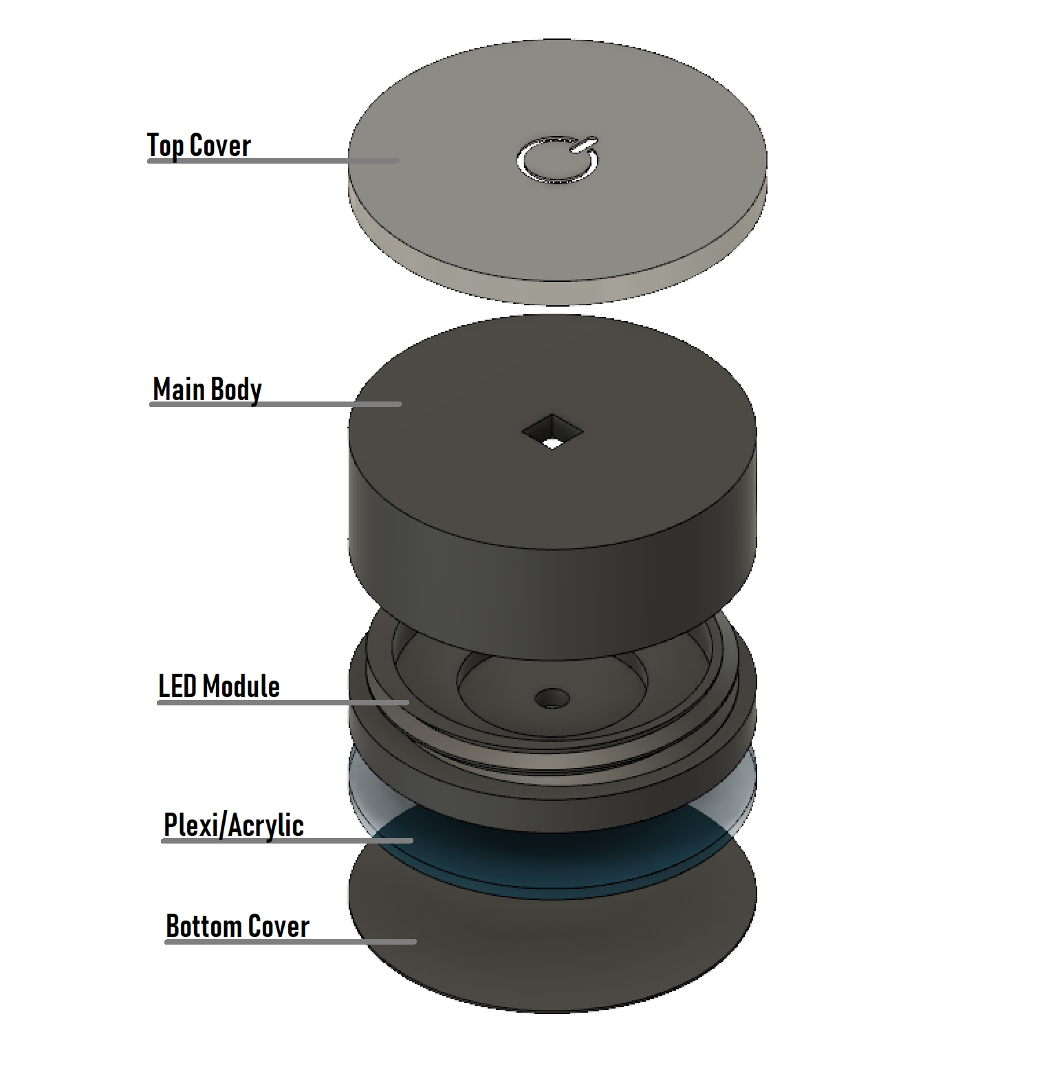
There are 4 parts to be printed:
-Top Cover
-Main Body
-LED Module
-Bottom Cover (optional)
The "Bottom Cover" is optional however it is recommended as it protects the acrylic from scratches
The "Main Body", "LED Module" and "Bottom Cover" are recommended to be printed together with the following settings:
-Resolution: 0.2
-Infill: 20%
-Supports: None
-Rafts: None
-Material: PLA
Estimated Print Time: ~3 Hours
The "Top Cover" 'must' be printed with the following settings:
-Resolution: 0.15
-Infill: 20%
-Supports: None
-Rafts: None
-Material: PLA
Important:
The power logo cutout is intentional. The large round cutout together with the thinness enables the button to be easily pressed. Pay extra care when removing it from the print bed.
Estimated Print Time: ~20 Minutes
Circular Acrylic
You need a circular acrylic disc with 60mm diameter and 2mm thick. Use a circle cutter
to cut the circle precisely and remove the roughness around the disc using sand papers.
Note: Using a 3mm thick acrylic may look better but it is a bit harder to cut. You may order 60mm acrylic discs from Aliexpress or your local (web)shops or even CNC one if you own a CNC machine.
Assembly of the Button:
Please watch the video for the proper assembly of the button.
[https://youtu.be/Z5WMYq_Oz_A](https://youtu.be/Z5WMYq_Oz_A)
Arduino Software
Code:
int led = 9; // the PWM pin the LED is attached to
const int f_panel = 8; // motherboard's PW_LED pin(+)
int brightness = 0; // how bright the LED is
int fadeAmount = 5; // how many points to fade the LED by
int PC_State = 0; // PC on/off
// the setup routine runs once when you press reset:
void setup() {
// declare pin 9 to be an output:
pinMode(led, OUTPUT);
// declare pin 8 to be an input:
pinMode(f_panel, INPUT);
}
// the loop routine runs over and over again forever:
void loop() {
// check if PC is on:
PC_State = digitalRead(f_panel);
// If PC is ON:
if (PC_State == HIGH) {
// set the brightness of pin 9:
analogWrite(led, brightness);
// change the brightness for next time through the loop:
brightness = brightness + fadeAmount;
// reverse the direction of the fading at the ends of the fade:
if (brightness == 0 || brightness == 255) {
fadeAmount = -fadeAmount ;
}
}
// If PC is OFF:
else {
// turn LED off:
digitalWrite(led, LOW);
}
// wait for 30 milliseconds to see the dimming effect
delay(30);
}
Wiring
Option 1 (with Arduino)
Note I:
Please read the user's manual of your motherboard carefully. Your motherboard may have different front panel header!
Note II:
The button does not need debouncing (ignore this if you do not know what debouncing is)
Note III:
Use the following link to calculate the value of the resistor:
[http://ledcalc.com/](http://ledcalc.com/)
-Google your motherboard's user's manual
-Look for "Front Panel Header" drawing
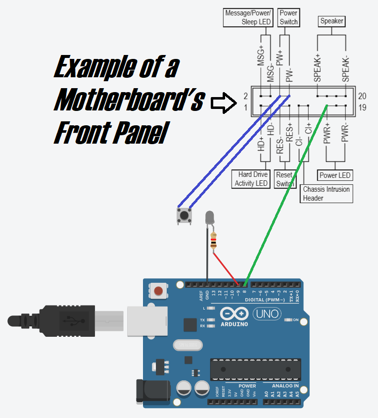
PW+ and PW-
These pins are connected to the power button on your computer's case. When these two pins are shorted (there is no polarity), your computer turns on.
You have two options:
1)Keep the case's button connected and connect the new button to the same pins of the connector
2)Replace the case's button with the new one
PWR+
Arduino pin 8 senses whether the computer is turned on or off through this pin. PWR- is not necessary if the arduino is connected to the computer via USB.
LED
The LED+ must be connected to the pin 9 of the Arduino and LED- to GND.
 Option 2 (without Arduino)
Note I:
Please read the user's manual of your motherboard carefully. Your motherboard may have different front panel header!
Note II:
The button does not need debouncing (ignore this if you do not know what debouncing is)
Note III:
The LED does not need a resistor
-Google your motherboard's user's manual
-Look for "Front Panel Header" drawing
PW+ and PW-
These pins are connected to the power button on your computer's case. When these two pins are shorted (there is no polarity), your computer turns on.
You have two options:
1)Keep the case's button connected and connect the new button to the same pins of the connector
2)Replace the case's button with the new one
PWR+ and PWR-
The LED+ must be connected to PWR+ and LED- to PWR-.

Made one?
Please share a photo of the button on your desk!
Illuminating Computer Power Button

Publicado em 27 de abr de 2025