Você está no 3DFinder
Buscamos em Thingiverse, MakerWorld e Printables ao mesmo tempo para te dar o melhor de cada uma.
Descrição
The next version will include more hooks and a back plate for command strips!
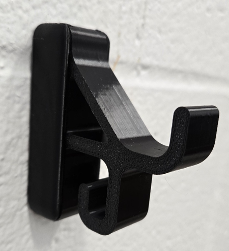
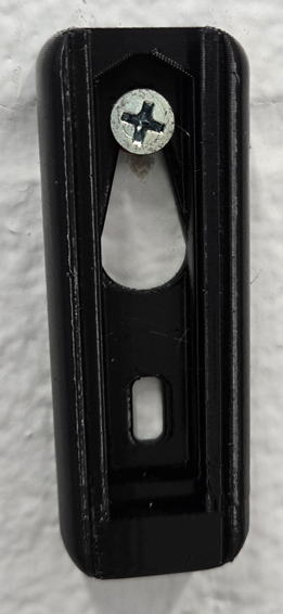
This design is an over-under wall hook meant to be put onto existing screws. A sliding mechanism hides the screw holes and allows for future modular hooks.
This was printed and tested in PETG. It's strength from a PLA print has not been tested.
Conception
This project originated from the idea that I have a bunch of screws in my walls with nothing on them. I wanted to make a wall hook that could easily latch onto these screws. What started off as just making a simple hook changed into the idea that I wanted a modular hook. I wanted to be able to attach a base and then swap it with different hooks for whatever my needs might be. I also wanted to be able to develop a base that allowed command strips. The overall goal became to make two bases and at least three swappable hooks.
Initial Design
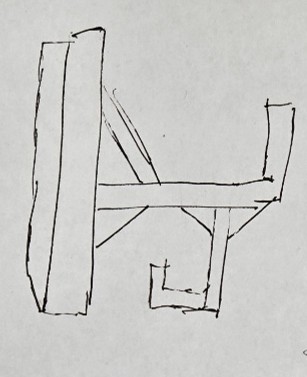
I began looking at different hook designs online: Amazon and MakerWorld. One thing I noticed is no one did an “over/under” double hook style. So, I made a few rough sketches on printer paper until I found an overall design I liked.
Now, it was time to get a more accurate sketch. But I had two problems that came up.
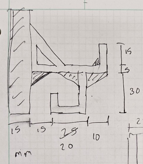
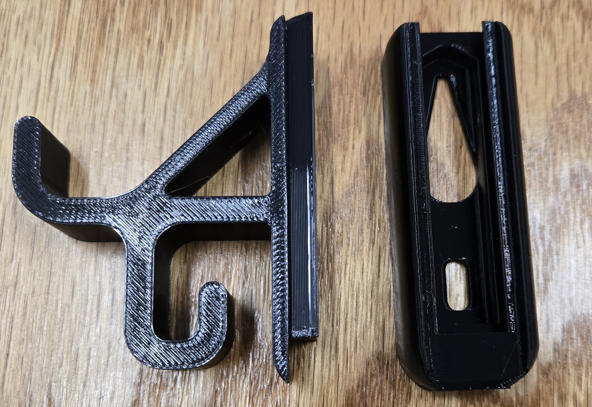
I needed it to be modular. So I decided on a sliding dovetail connector. Because of the cross sections of the dovetail, I figured I had to print the straight up (note how the bottom hook lines up with the base on the left). You’ll notice the chamfers and edges to make it easy to 3D print with no supports.
I had no idea what ratios I should use while putting my design into CAD. So, what if I turned to Engineering Paper? Each small square is 1/5”. I could just assume that is about 1 mm (It’s easier to work in mm for 3D printing) and get a good idea for proportions.
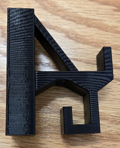
With these two problems solved. I drafted and printed my first version of the hook. There were a couple small changes in SolidWorks from my initial hand sketch, but overall, a pretty good rough draft.
I put this on hold because I needed to address the most difficult part of this entire design: the sliding connector.
|
 |
Sliding Connector
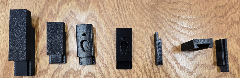
To design the sliding connector, I just built a small part. There’s no need to waste material and time on the entire hook when I’m just focusing on the connector. It took me 7 iterations before I reached my final design. (Version 5 failed to print the first time).
Version 1: Just a simple sliding connector just to learn how to CAD it. Units were in inches and the part was larger than initially planned. I also had too large of a gap, but this was on purpose because it’s just a proof of concept. Now I know the process for how to CAD a sliding connector, time to refine it.
Version 2: Smaller, in mm, and I wanted to have more contact area for the transfer of forces. I realized with V1 that there was barely any surface area to distribute the forces and it be likely to break.
Version 3: I want to make it easier to print vertically so I chamfered the end of the sliding portion. I also added in a recessed area for the screws. I found out I didn’t leave enough of a gap for the head of some of the screws, so I need to find a way to hide the screw better without making the part thicker. I also settled on a gap of 0.05 mm.
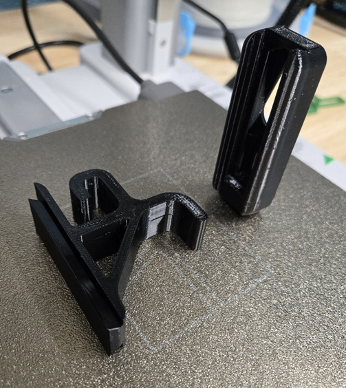
Version 4: I adjusted the gap to work with screws. It worked well! However, I realized the printing orientation was wrong. If I were to hang anything on the hook, it would break. I need to print the hook on its side, not vertically. But how can I print the dovetail on its side with the overhangs? What if I print the wall connector vertically and the hook sidesway? Then I cut the hook a little bit so the edge of the dovetail starts on the plate.
Version 5: I’m now working on just the hook portion. I cut it, but with only 1 line of filament, it doesn’t stick to the plate. With 2 lines, it sticks to the plate. But the tolerances are off and it won’t slide in.
Version 6: The gap is now 0.1 mm. I print both pieces and it slides in.
Now that I have the connector mechanism, time to redesign and print the entire hook.
New Hook Plus Mechanism
I drafted a new hook design, knowing the new printing orientation for the hook part was sideways. I added a few fillets to make it look nice. You’ll also notice the upper diagonal; this was added for strength and to force things that are hanging towards the edge of the hook so it doesn’t interfere with what hangs below. Then I implemented the sliding connector. I did have to play with the interfacing gap a bit and settled on 0.15 mm. Then I made everything look natural. We printed this with PETG used a force gauge on the final design and it was able to hold at least 20 lbs on each hook (not tested at the same time). We didn’t test above 20 lbs.
 |  |
 |  |

Gostou deste modelo? Crie uma conta grátis para salvar seus favoritos e voltar a eles depois.
Criar conta