Você está no 3DFinder
Buscamos em Thingiverse, MakerWorld e Printables ao mesmo tempo para te dar o melhor de cada uma.
Descrição
Introduction
I’ve had this idea in mind for the last few years and have finally decided to sit down and work on it. I want to warn you that this is quite an involved project. It will require some consideration of print profiles, soldering skills, a custom PCB order from JLC, and familiarity with the Arduino IDE.
The goal of the project was to create a rotating globe that indicated the position of the sun throughout the day. As the day progressed, the globe would rotate to follow the sun's zenith. At midday in your location, the globe would be positioned directly above you. The idea was to design a clock that, while not very effective, would be intriguing and engaging.
This guide is a work in progress, and I plan to update it as I continue developing this project. I’m aware that the codebase has some bugs and could be optimized. Additionally, I would like to integrate this device with Home Assistant, allowing me to use it for notifications or adjust brightness based on motion, for example.
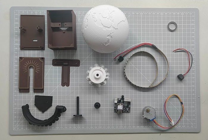
BOM
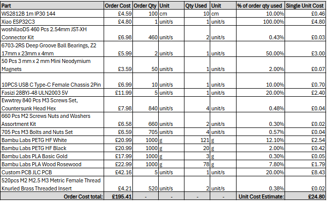
This project requires several items, and the total cost I spent on materials is approximately £195.38. It's important to note that many of these items came in packs containing multiple parts, while I only needed one of each. As a result, the average cost per unit is lower. Additionally, if you're willing to wait for parts from AliExpress or similar retailers, you could potentially save some money.
The single unit cost estimate is a little hard to work out exactly, my estimate is that the cost of the materials used in a single unit is ~£24.80, below you can see how I calculated that out.
Programming Guide
The code base for this project can be found on git hub here - [https://github.com/Jacksoldano/GlobeClock/tree/main](https://github.com/Jacksoldano/GlobeClock/tree/main)
I recommend programming the Xiao board before you begin the assembly.
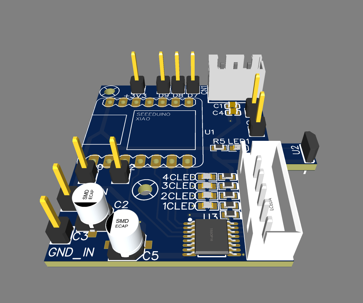
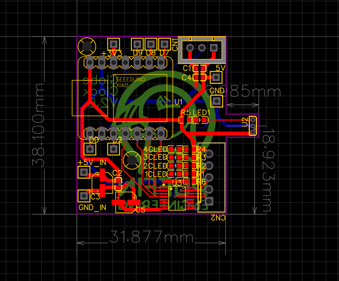
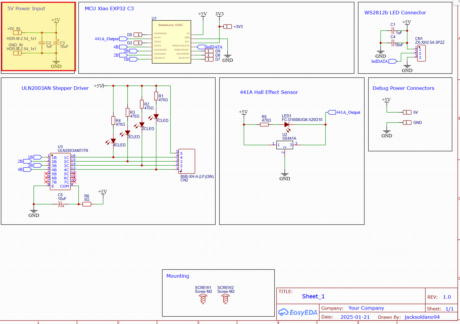
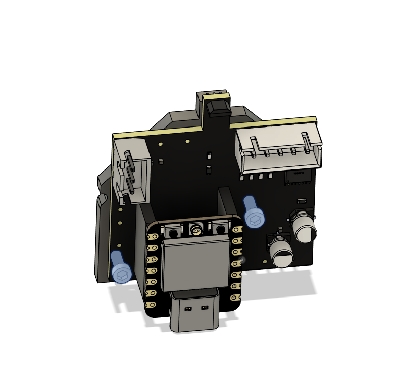
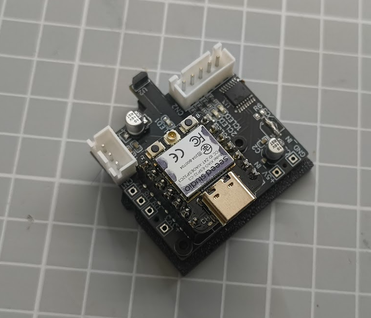
Custom PCB
The PCB files can be found here - [https://oshwlab.com/jacksoldano94/clock-test](https://oshwlab.com/jacksoldano94/clock-test)
Print Profiles Suggestions
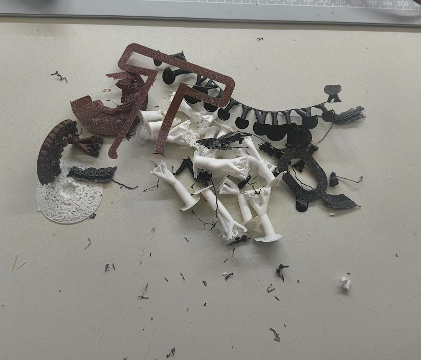
I'm not confident these are the best print settings, but what I suggest here has worked for me for each part 2 times.
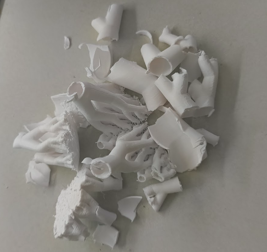
As you can see below, I went through a few prototype prints….
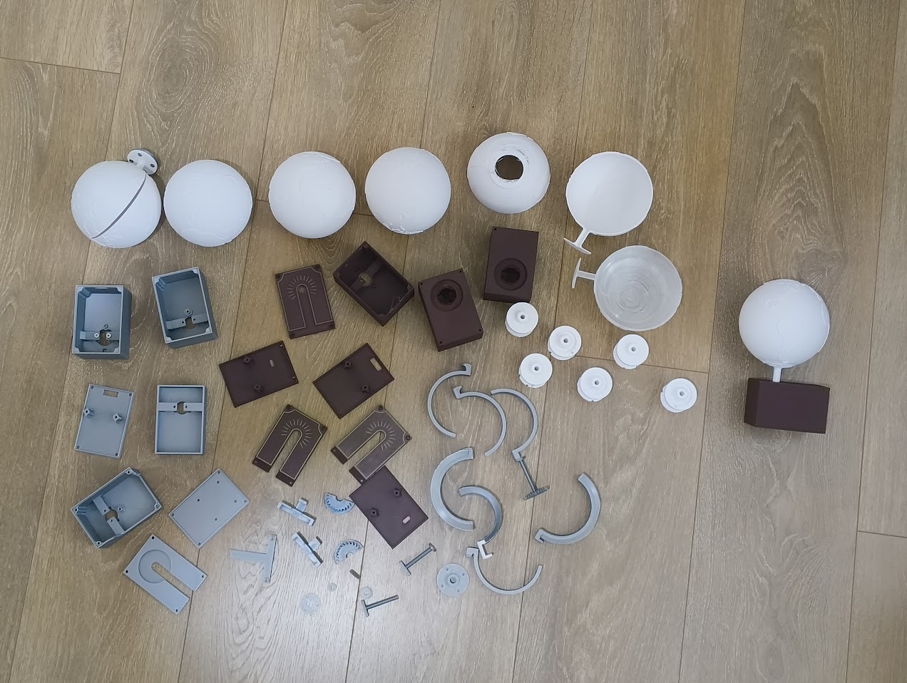
Plate 1
- Black Light Guide 12mm - Tree Supports enabled, 0.2mm layer height
- Black Light Guide Pipe - Brim Enabled, 0.2mm layer height
- Black mid Gear - 0.2mm Layer Height
- Black PCB Carrier - 0.2mm Layer Height
Plate 2
- Inlay parts should all be gold PLA
- Enclosure Cap should be wood PLA, enable brim & tree supports, 0.2mm Layer Height
Plate 3
- Globe (This is the hardest part, open for suggestions on how to improve the print quality of this part) - 0.12mm Layer Height, Tree Supports, 30deg threshold angle
Plate 4
- Globe Gear - 0.12mm Layer Height, Tree supports
Plate 5
- Box Base - Wood PLA, 0.2mm Layer Height
- Box Top Bearing - Wood PLA, 0.2mm Layer Height, Tree Supports
- Enclosure Cap T Joint - Wood PLA, Brim, 0.2mm Layer Height
Assembly Guide
Print out the full set of parts
Carefully remove all the supports
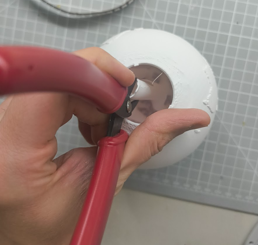
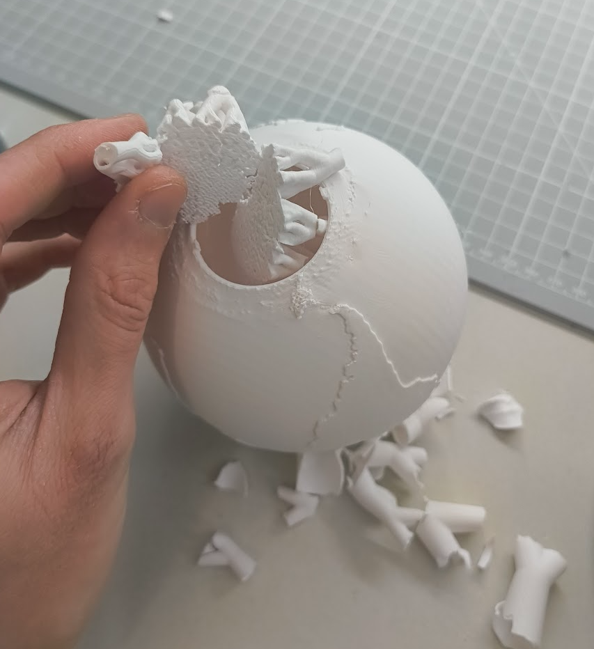
Be very careful with the globe print, the internal tree supports are hard to remove without damaging the alignment tabs…
I recommend using needle nose pliers to brake up the tree then use your hands and wire snips to break it down enough to fit through the hole. Open to suggestions on how to improve this process, everything else I tried failed.
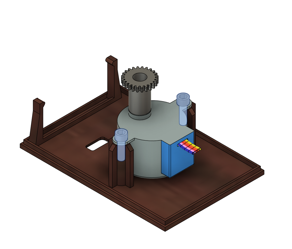
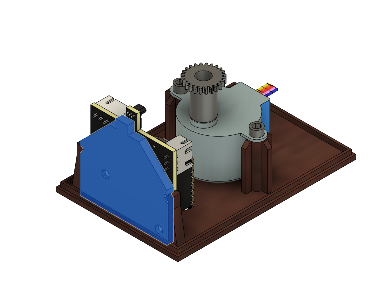
Add the gear to the stepper motor, use 2 M3 Cap head screws ~6mm
Now install the USB-C connetor into the slot on the rear of the main enclosure box.
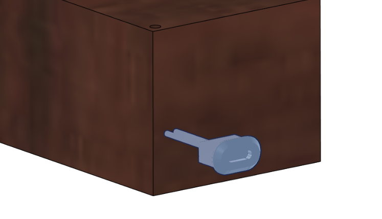
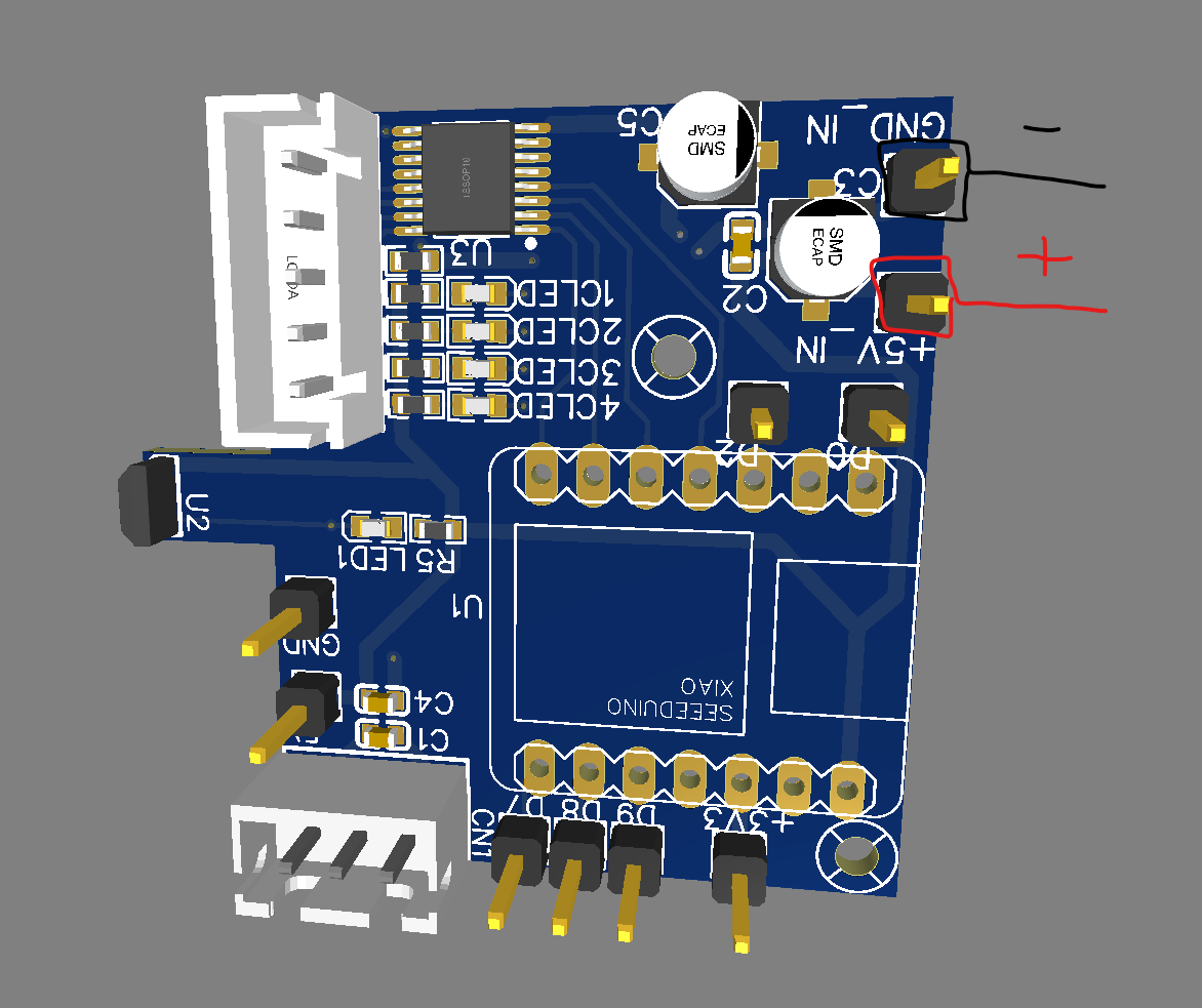
Solder the USB-C Connector to the PCBs power input pads
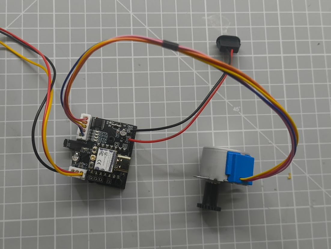
Now is a good time to prep the cables for the PCB, the LEDs will need a 3-way JST 2.54mm Female housing XH-3Y and the stepper motor uses a 5-way JST 2.54mm Female housing XH-5Y (Its likely the stepper will come pre-installed with these)
Install press fit insert into the PCB carrier board (Or print the 2mm screw hole version that does not require the inserts
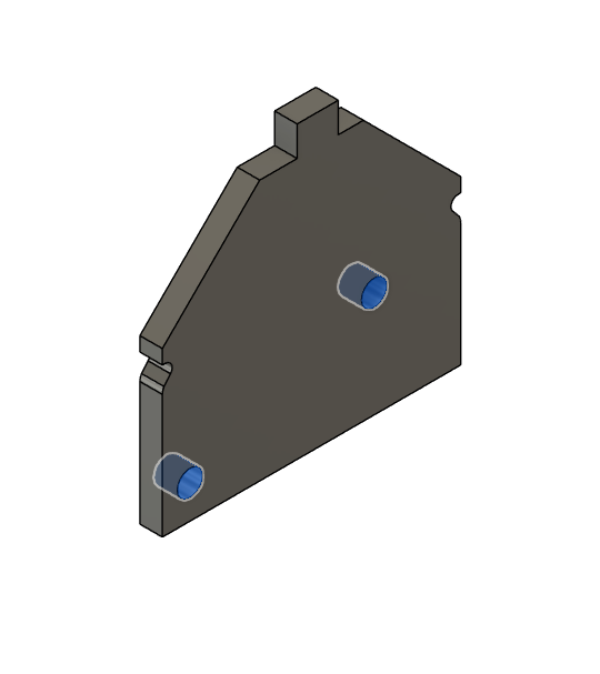
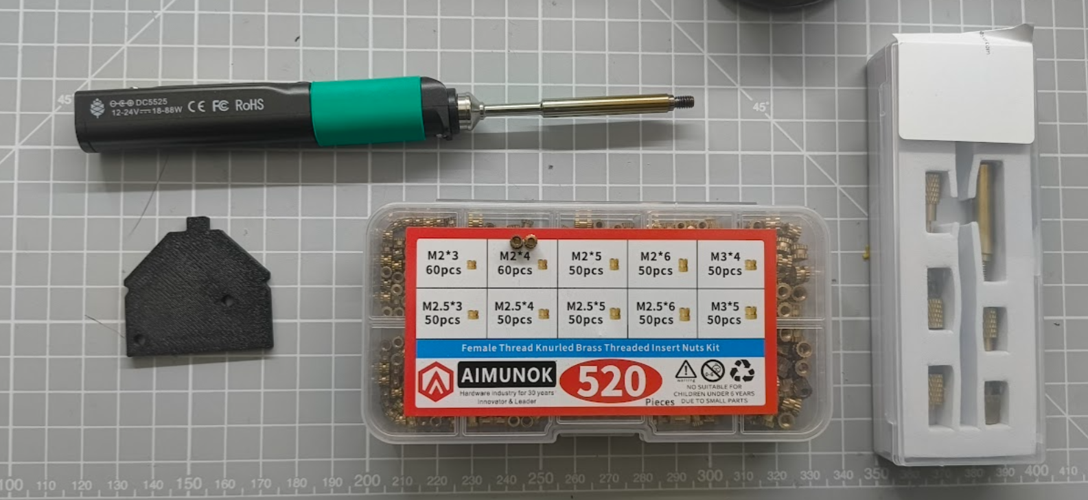
The easiest way to install the threaded inserts is with a threaded insert tip like I'm using here, we will install 2x M2*4mm inserts into the two slots on the PCB carrier part.
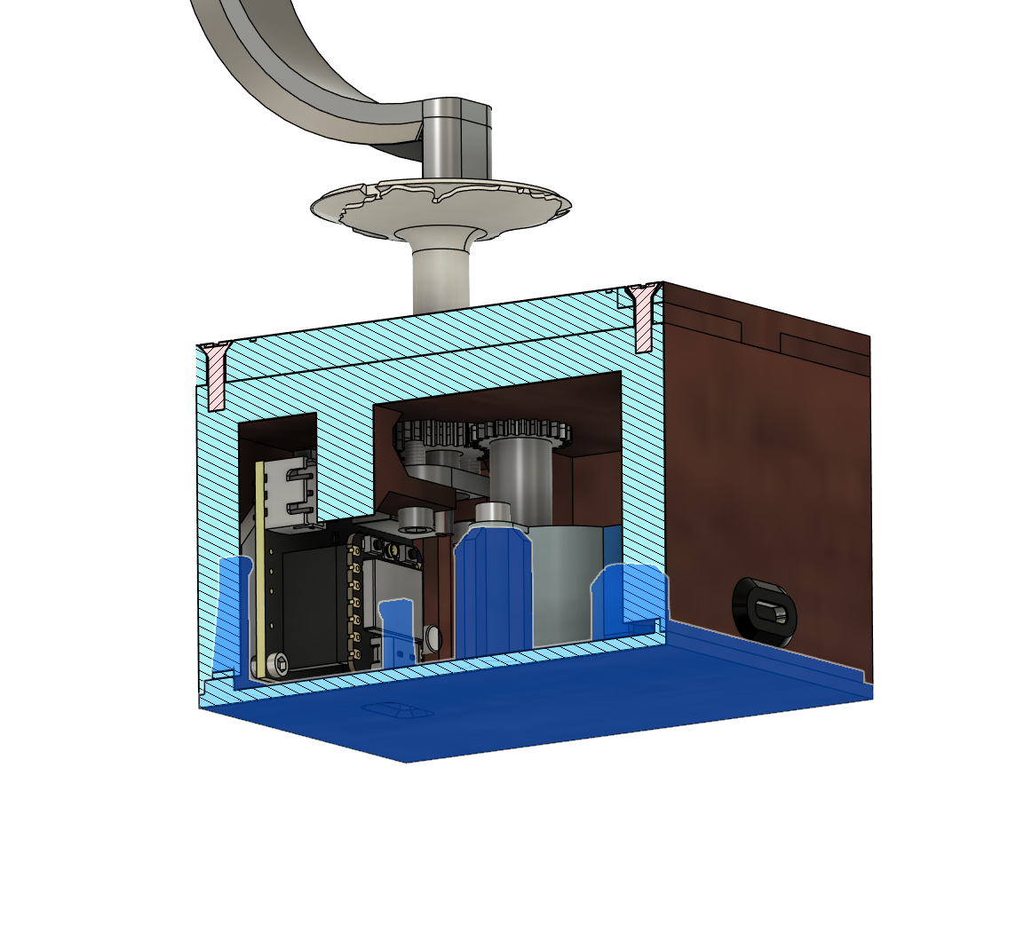
Install the custom PCB onto the PCB carrier using 2x M2x6mm Cap screws
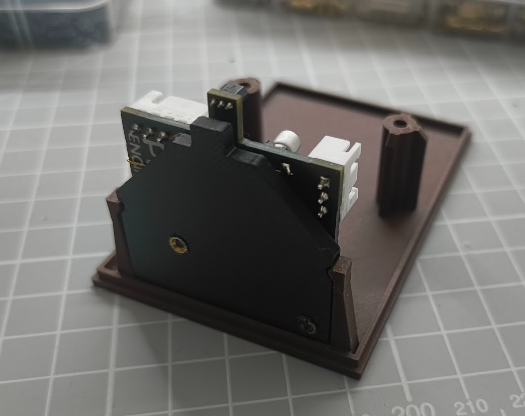
Now install the PCB carrier into the Wood PLA base plate slots
Now go to the Globe gear part, and install the 3 mm x 2 mm Mini Neodymium Magnets, check the polarity with the PCB the green indicator LED should light up when the magnet is near in the correct orientation.
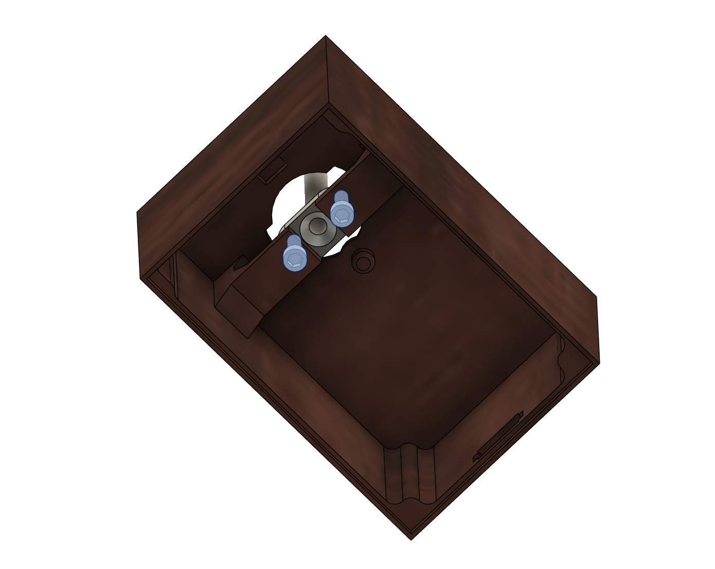
Now install the LED wire pipe onto the top casework part
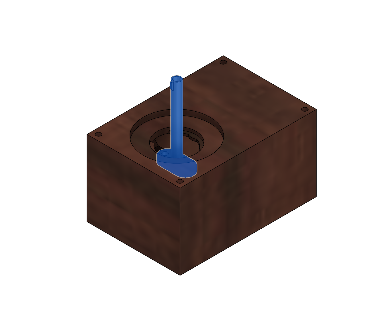
Secure this part using the 2 screw holes
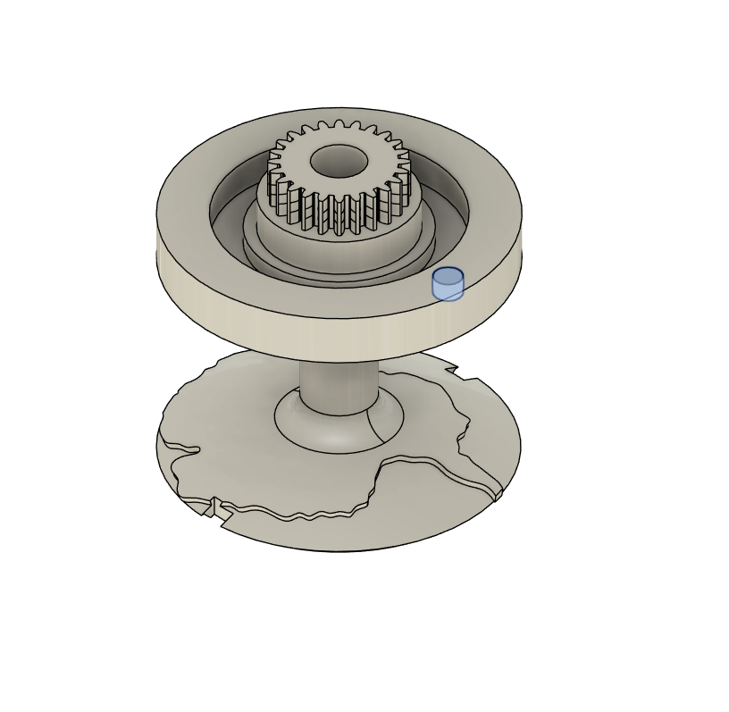
Now install the 6703-2RS bearing into the slot
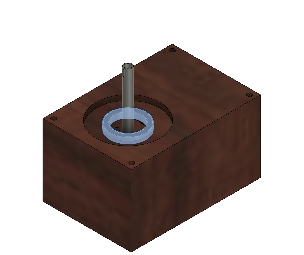
Slot the globe gear other the tube, this might be a little stiff be carefull not to break it by applying to much force
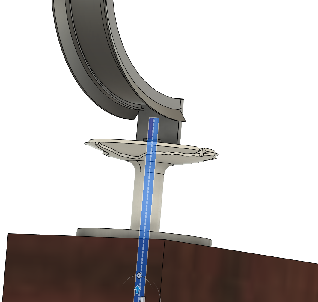
Install the LED guide onto the light slot of the pipe

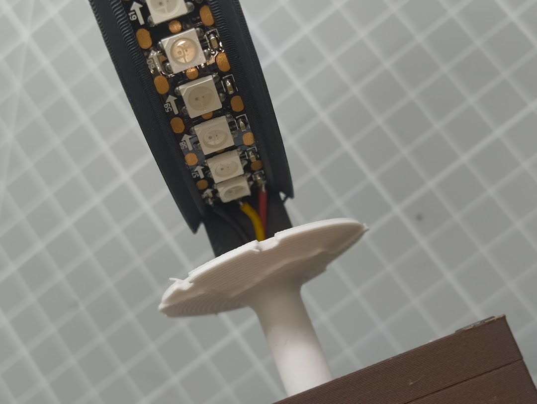
Thread 3 wires up the pip from the underside, these will be ground, +5v and data for the RGB LEDs
Solder the wires to the LED Strip, RED to +5V, Black to GND, White to Data
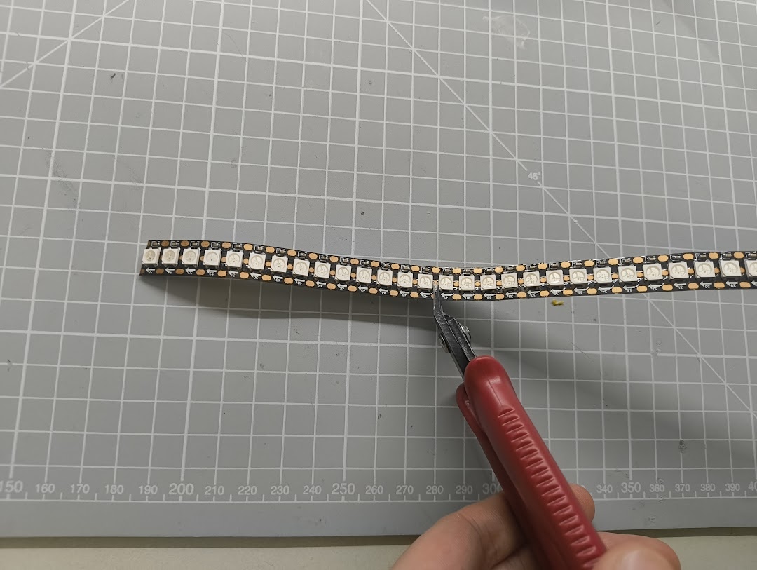
Cut down the LEDs strip into a segment of 14, I recommend you use a flush cutter for this. Make sure enough pad is left to solder to.
With the snipped LED strip, install it into the light guide using the open slot on the top
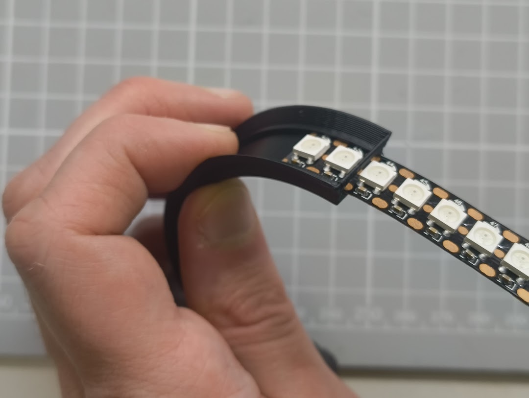
Do not fully insert the LEDs into the guide, as you will need to have room to solder the wires while in this position.
Once you solder thew wires push the LED strip down to the bottom of the guide like shown below.
Now install the gold trimmed top cover front part
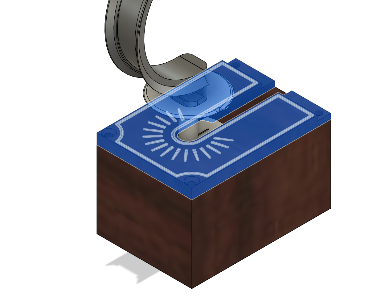
Then install the T-Cap on the top as well
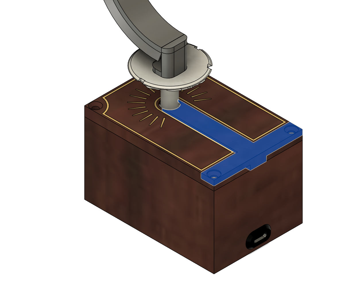
Secure the top plates with 4x countersunk M3 6mm screws
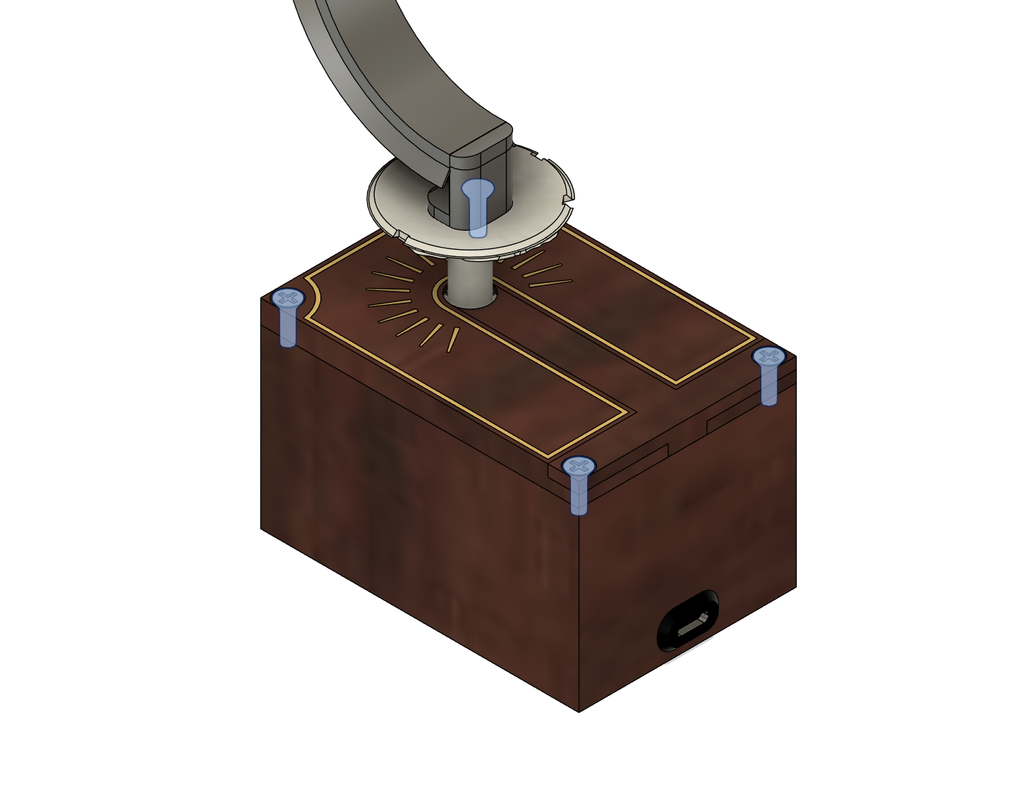
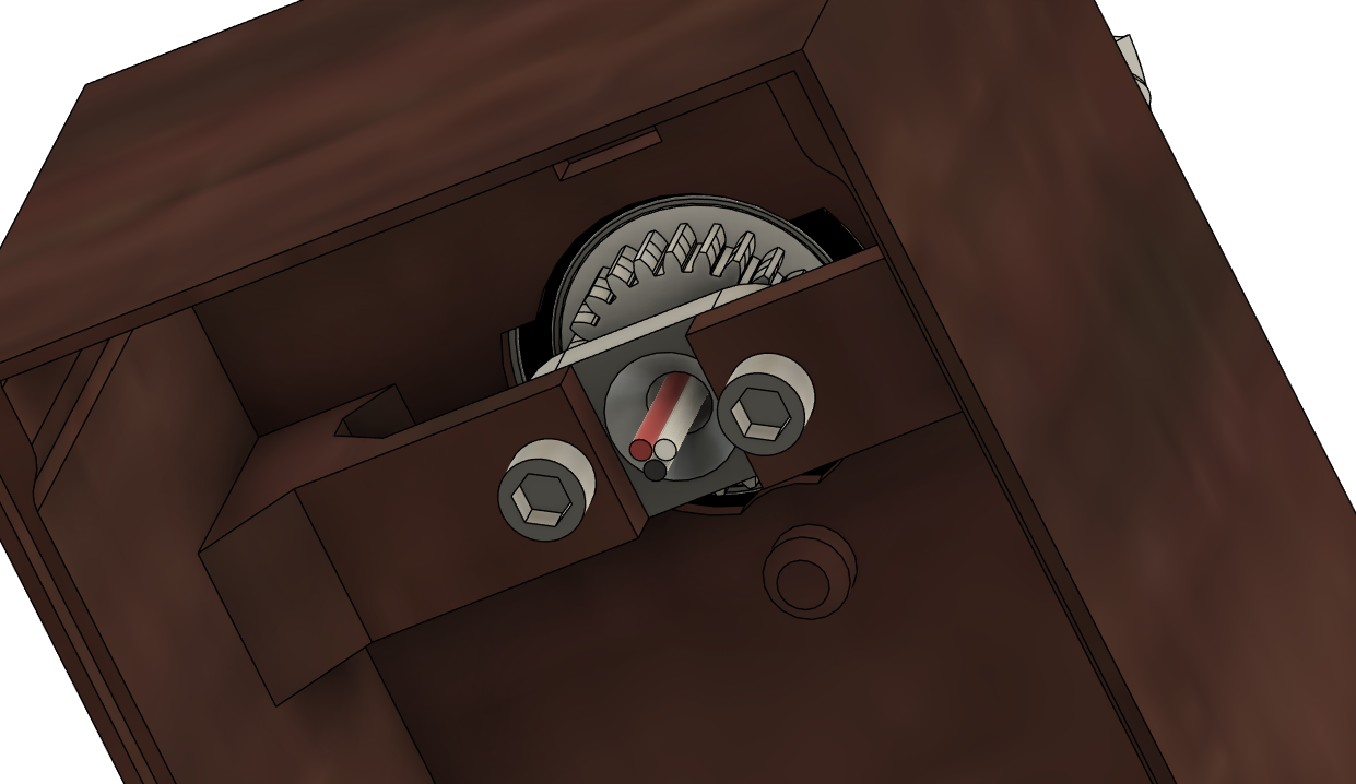
Now connect the motor, LED connectors & power to the custom PCB at the locations shown below…
MISSING
Close the box by press fitting the base plate into the main enclosure
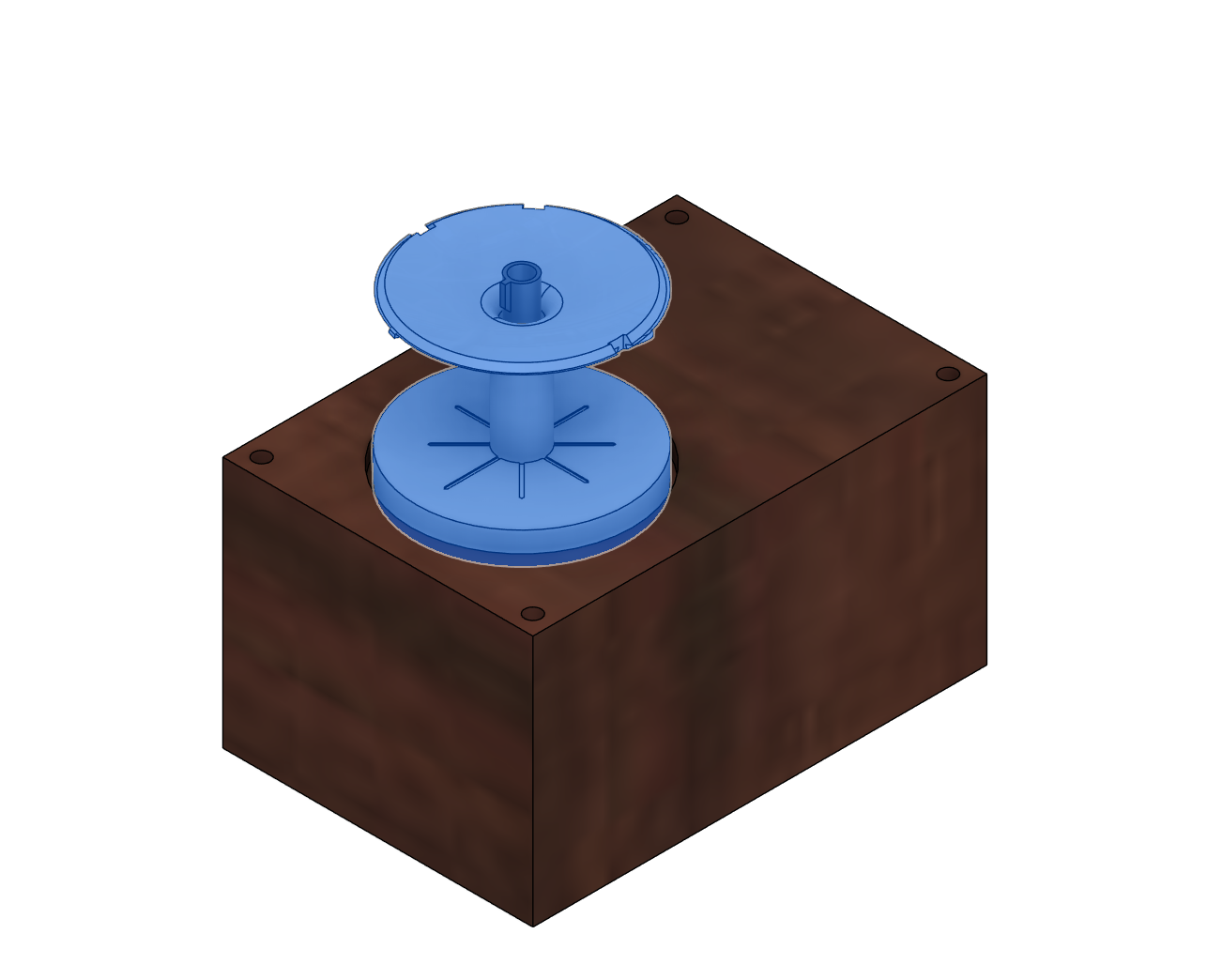
Install the globe top part onto the globe gear using the 3 pins
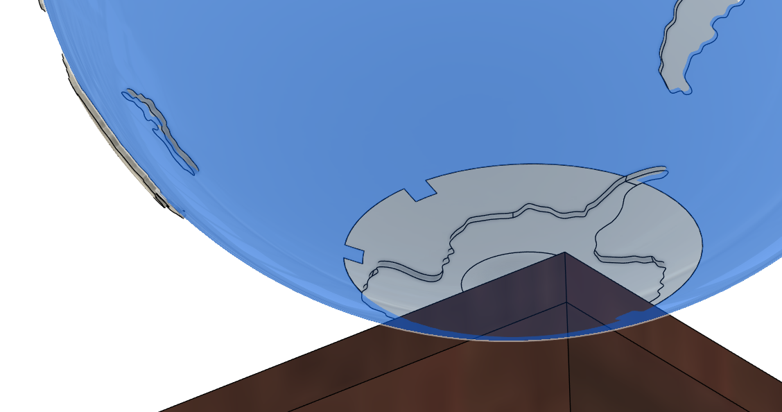
And now the model should be complete!

Switch it on and enjoy!

360° Rotating Globe Clock

Publicado em 20 de fev de 2025