Você está no 3DFinder
Buscamos em Thingiverse, MakerWorld e Printables ao mesmo tempo para te dar o melhor de cada uma.
Descrição
*Update 1/21/25 - Added lid cover that was missing from all print profiles. Please download again if you previously downloaded a profile. Sorry for any inconvenience!
Introduction
(NO AMS REQUIRED, A1 MINI COMPATIBLE)
This is my my take on a 3D printed vault, and I think it turned out great!
I've gone for a sci-fi theme that I think will look good in many color combinations. There are features included for an LED COB light strip that gives a really nice glow to the clear tube. And even without the lights, the details and stand make this an exceptional showpiece.
One of the most important things about a a vault is internal gears and bar extending mechanisms in the door. Here the gears are mostly for show, but the lid is designed in a way to see the moving internals. Being 3d printed and having a clear tube, this is not really meant for safe storage of valuables, but more as a display piece. As such, there is no key or locking mechanism - just rotate the handle roughly ½ turn clockwise to latch the vault lid, or rotate the other way to unlatch.
I think this would be a great display to showcase minis or your favorite figurines, but there are many possibilities.
Keep reading for printing info and assembly instructions.
Purchased Parts
The design is fairly intricate and involves some assembly . Most of the fits are designed to snap together with a mild friction fit to limit the amount of purchased parts required. The bare minimum needed to assemble this is, the clear acrylic tube and a couple m3 screws and nuts.
The light really takes this to the next level, so I recommend getting those parts to complete the build! You will need a the maker supply electronics bundle (or a switch, usb cable, a power distribution board, and a couple cables), and a 300mm COB light strip.
Printing
- Use my profiles for intended part orientation and print settings.
- The only part that needs support is the two outer shell pieces
- There are several parts that have print-in-place motion - make sure to free them up if they come off the build plate stiff.
- The end cap is a little different for the with electronics version vs without electronics. So for simplicity I've created separate profiles for with and without electronics that have all the parts needed for each version. Also included are profiles for A1 Mini
- I recommend silk filaments for the outside parts, while the clamp collar should be regular pla as silk filaments typically have very poor mechanical properties.
- If you're printing from the app and not using silk, be sure to change the profile to one for normal PLA (or whatever you are using)
- Note that some of the snap together fits are difficult to disassemble without breaking, so be careful when testing parts prior to assembly.
Assembly
Lid/door assembly
| 1. Ensure all the extension components of the lid bottom core are free to move in and out | 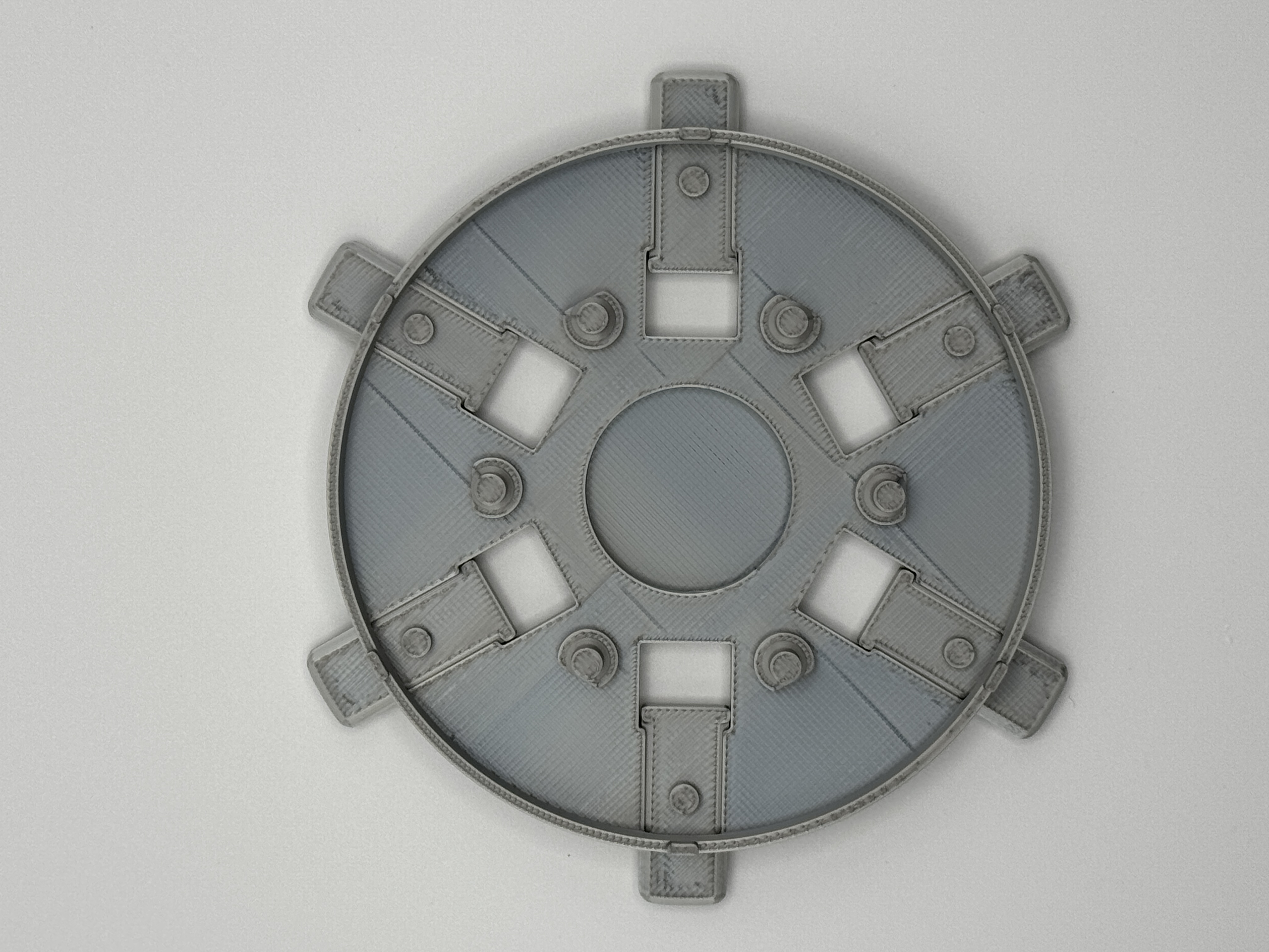 |
| 2. Install the slot ring and the outer ring gear, lining up the slots between the two to snap together. The little nubs on the ring should be facing up. | 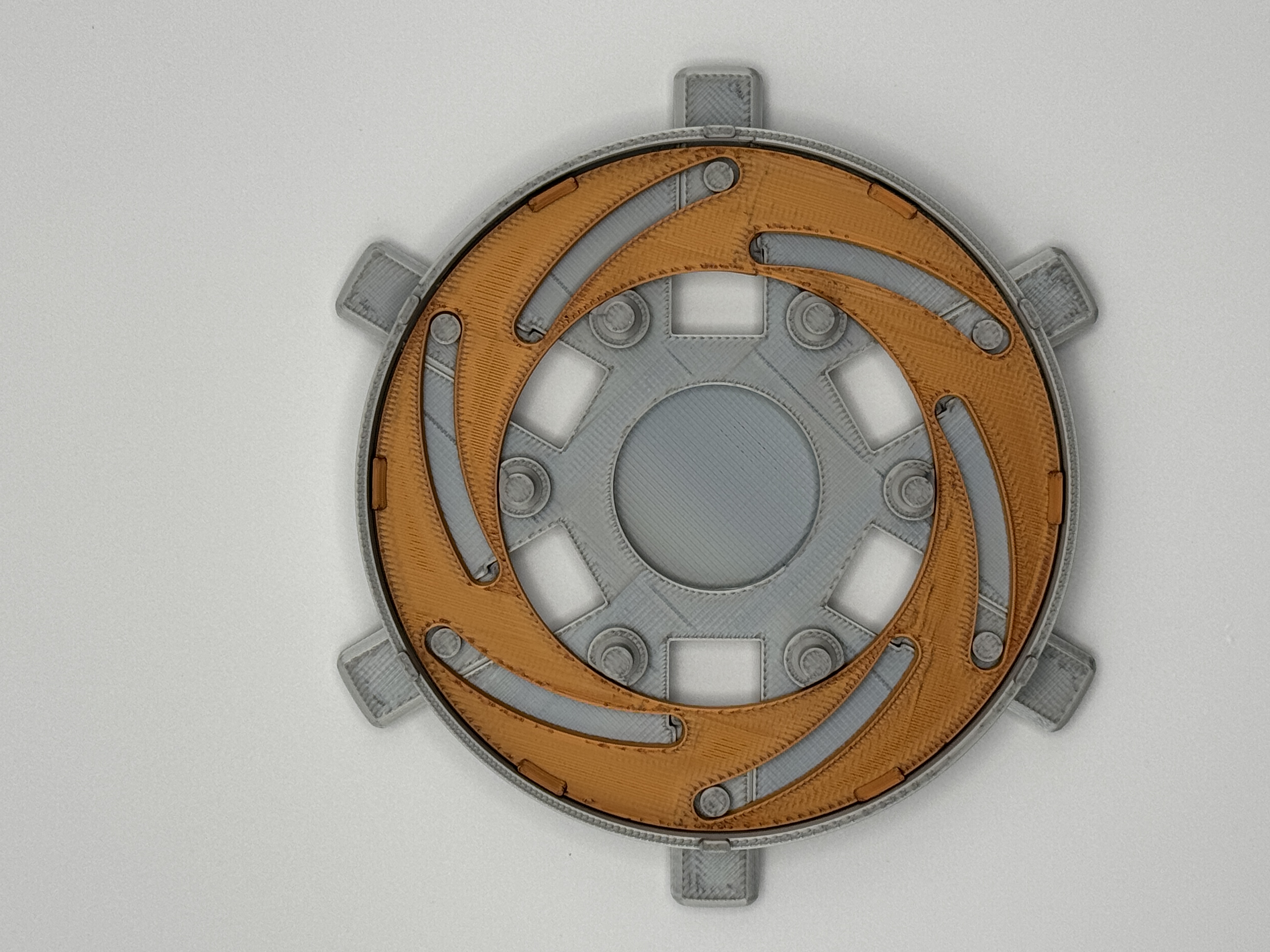
|
| 3. Install the outer ring gear, fitting the gear's slots onto the slot ring's nubs. |
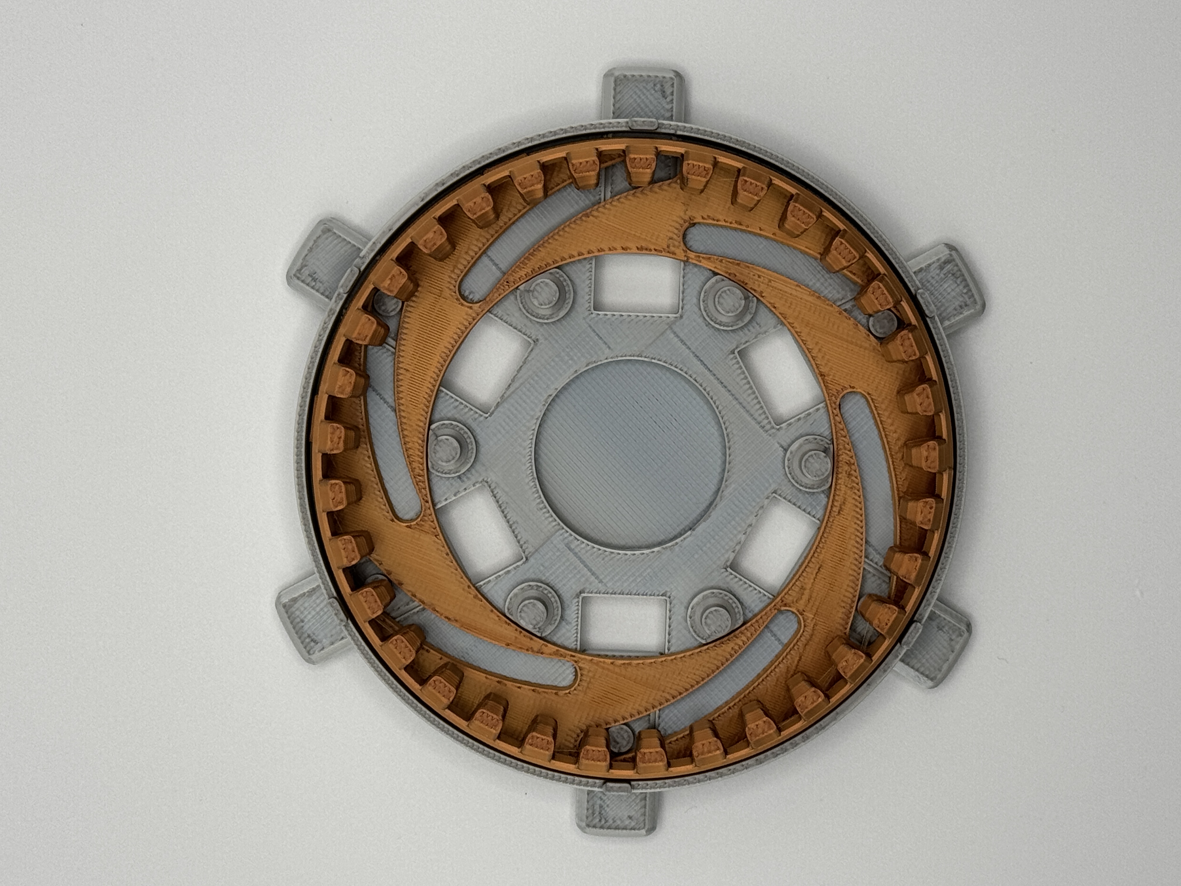 |
| 4. Place the 3 planet gears on alternating posts. (Doesn't matter which, just leave an empty post between each gear) | 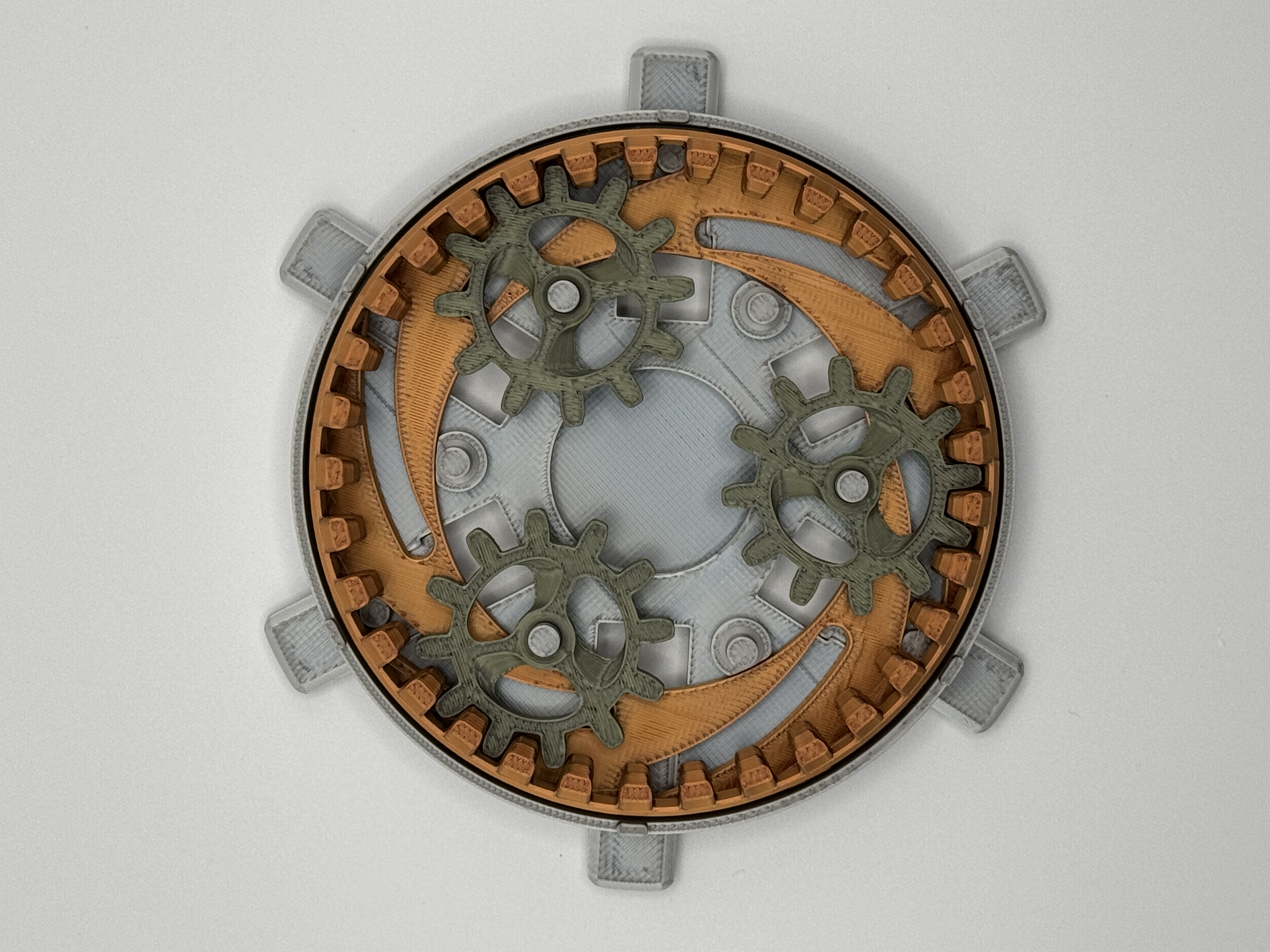
|
| 5. Place the sun Gear into the center. | 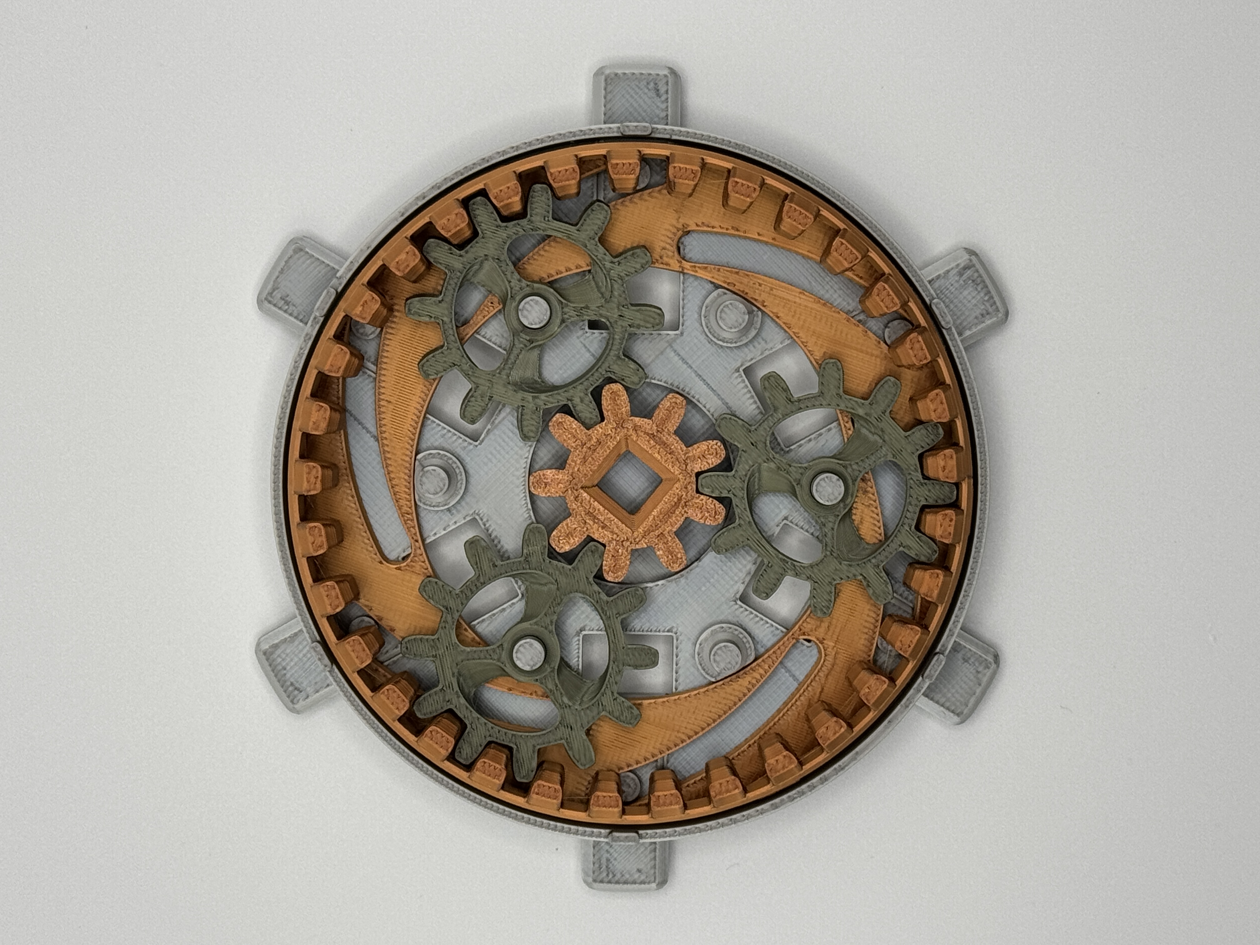
|
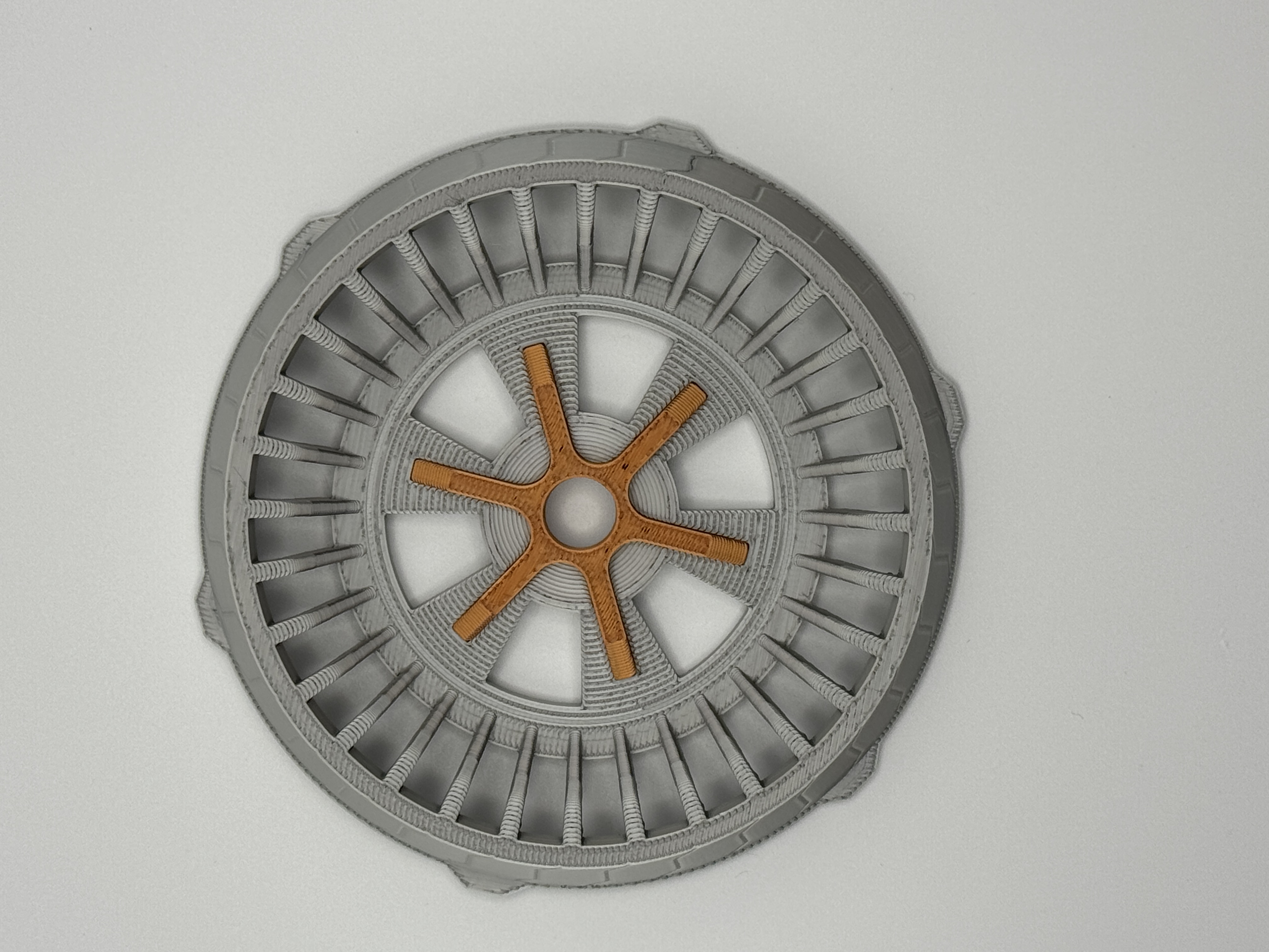
| 6. Install accent piece into the top cover. Note that this one is slightly smaller than the accent piece that goes in the other end. |
|
| 7. Aligning the pins and slots between the two parts, install the cover over the core and gear assembly. | 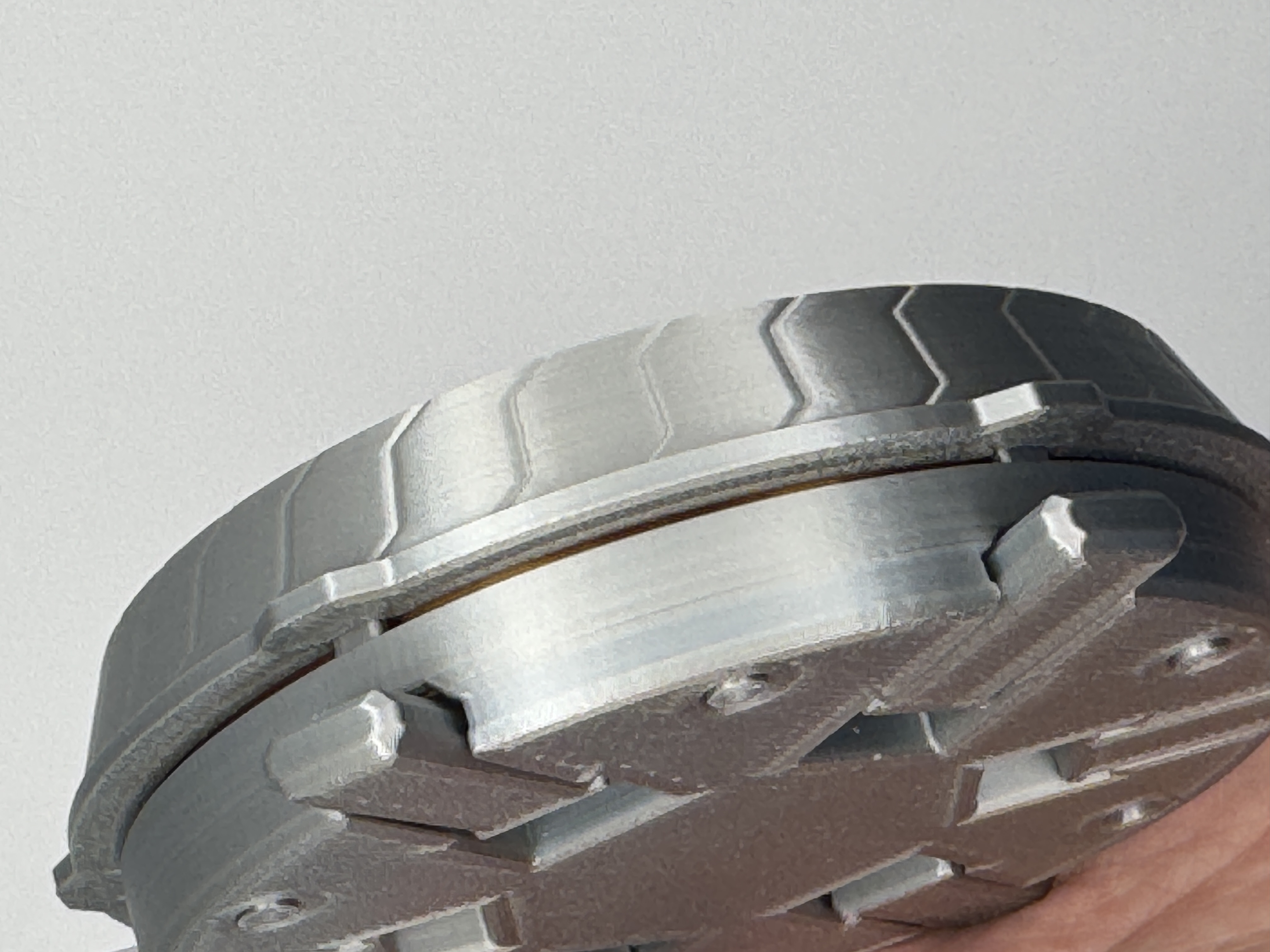
|
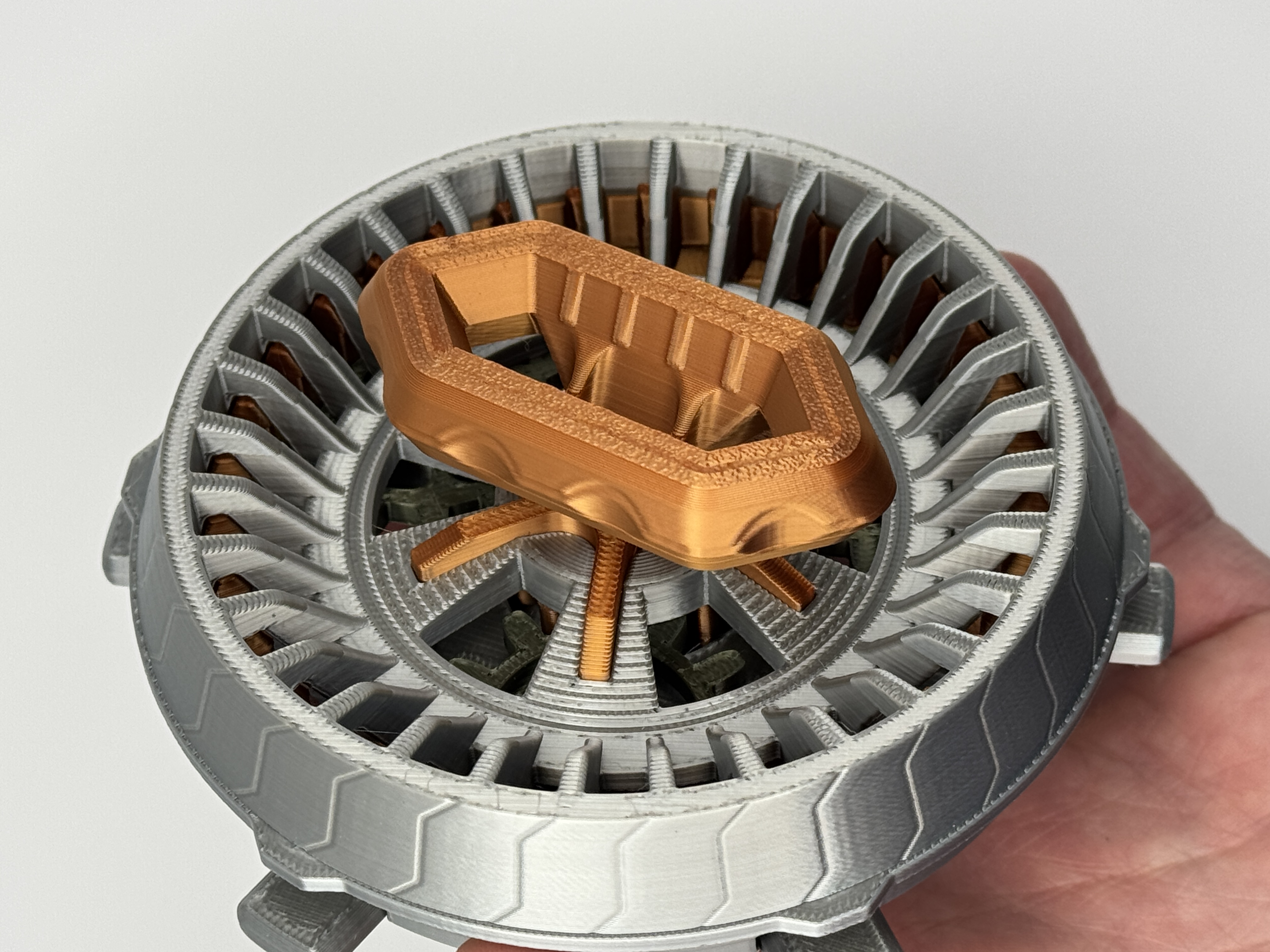
| 8. Insert the handle, being careful to press it on straight rather than angled. |
 |
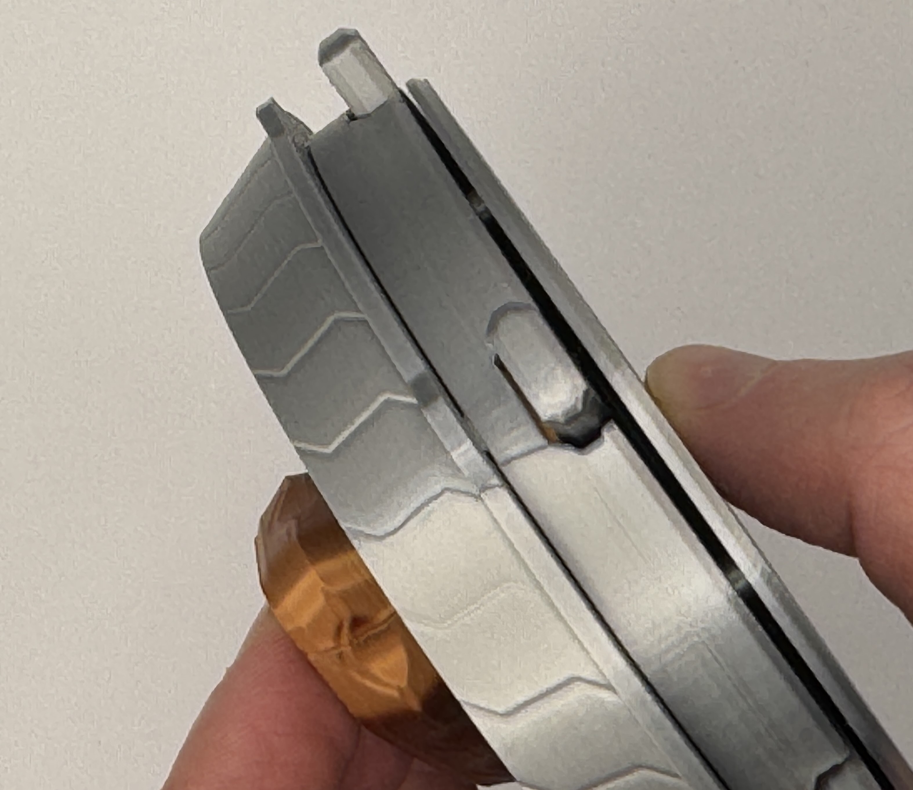
| 9. Install the bottom cover, aligning the pins between the parts. |
|
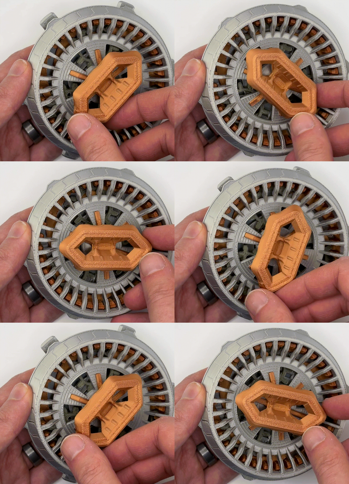
| 10. Ensure all of the parts move freely. If the connections to the top or bottom covers were not tight, you may want to carefully disassemble and reassemble installing with a few drops of glue at any pin connections. |
 |
Bottom Assembly (with electronics)
(If assembling the bottom without electronics, just install the corresponding accent piece and go continue to the next section)
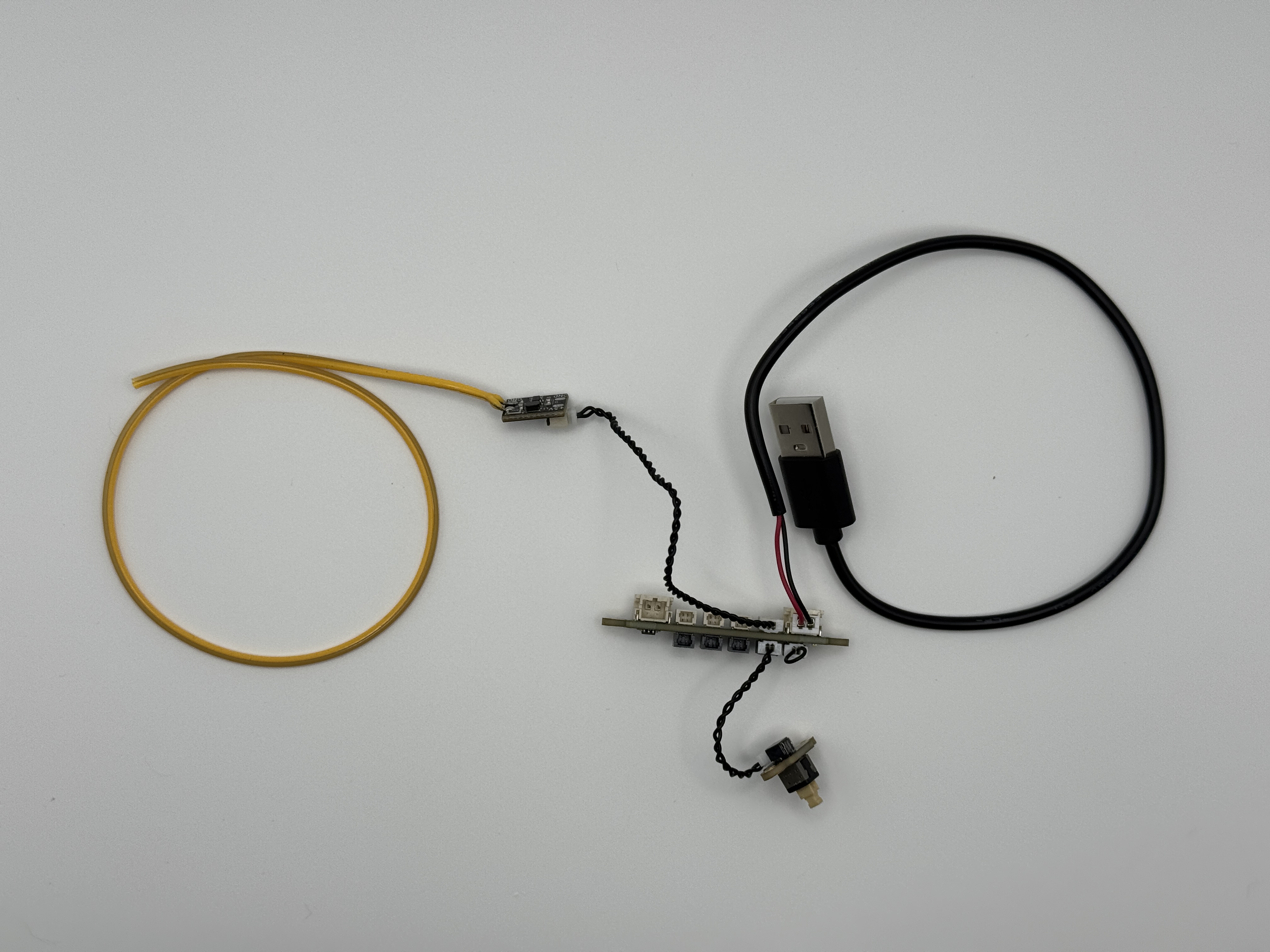
1. First build the circuit as shown, and test it to make sure it works as expected.
| 
|
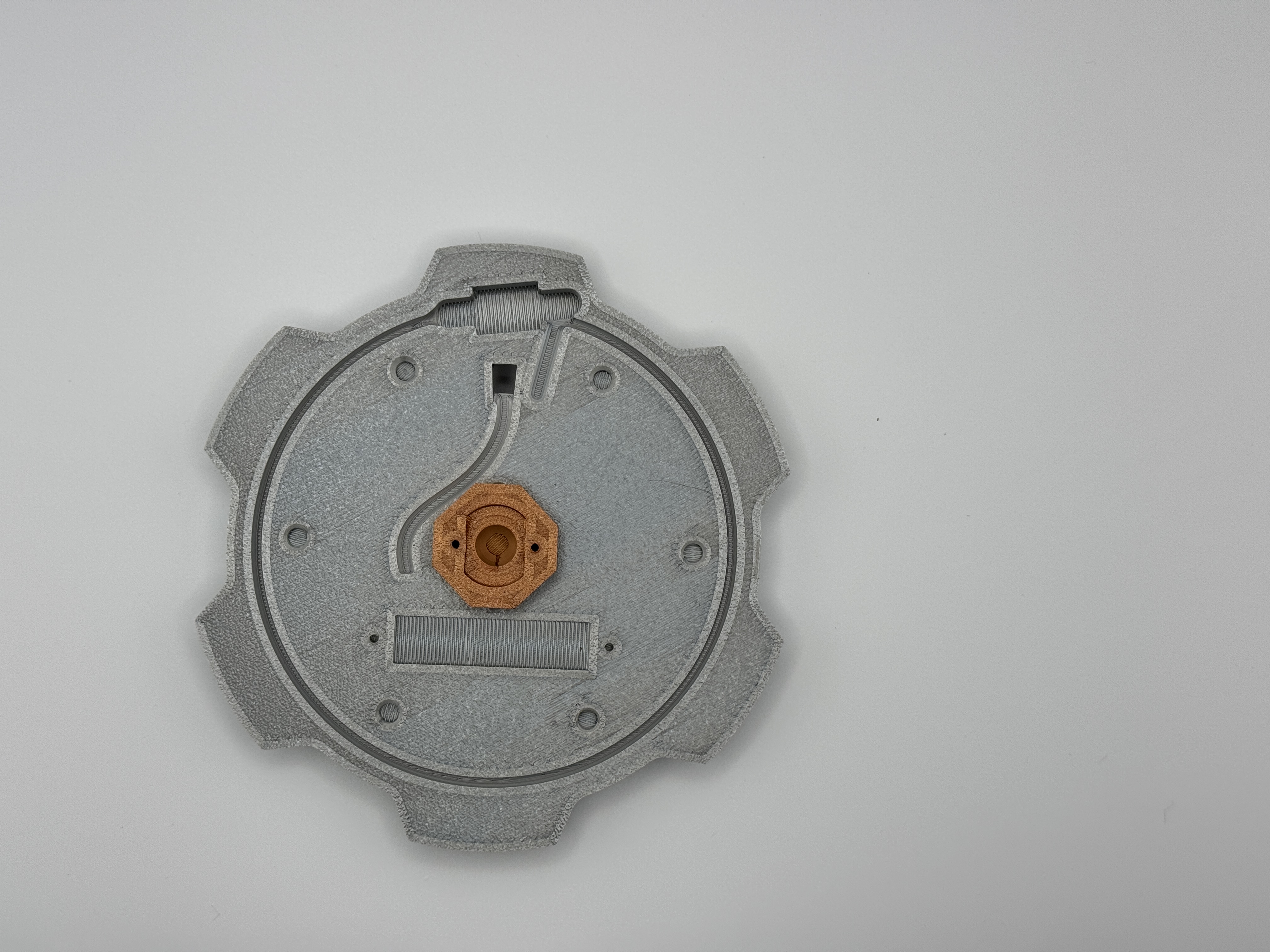
| 3. Ensure the button Insert moves freely, then install into the bottom cover as shown, lining up the two pins and pressing together. If the fit is not tight, install with a couple drops of glue. |
 |
| 4. Unplug and feed the white connector end of the USB cable through the bottom cover. Then plug it back into the distribution board. |
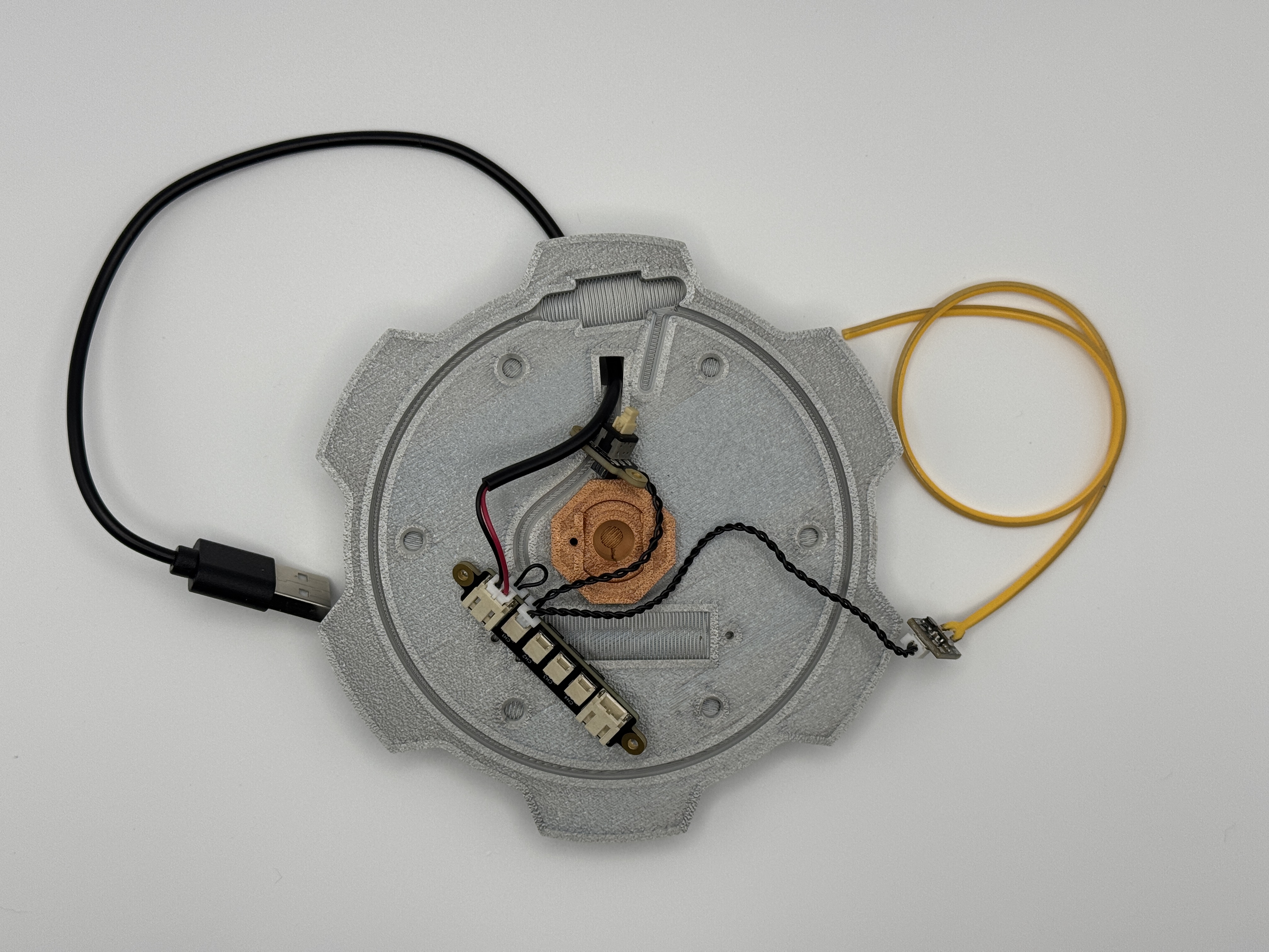 |
| 5. Position the power distribution board with the switch side (dark side) up over the rectangular cutout, and use (2) of the self tapping screws to secure in place. You should only need to screw a couple turns. | 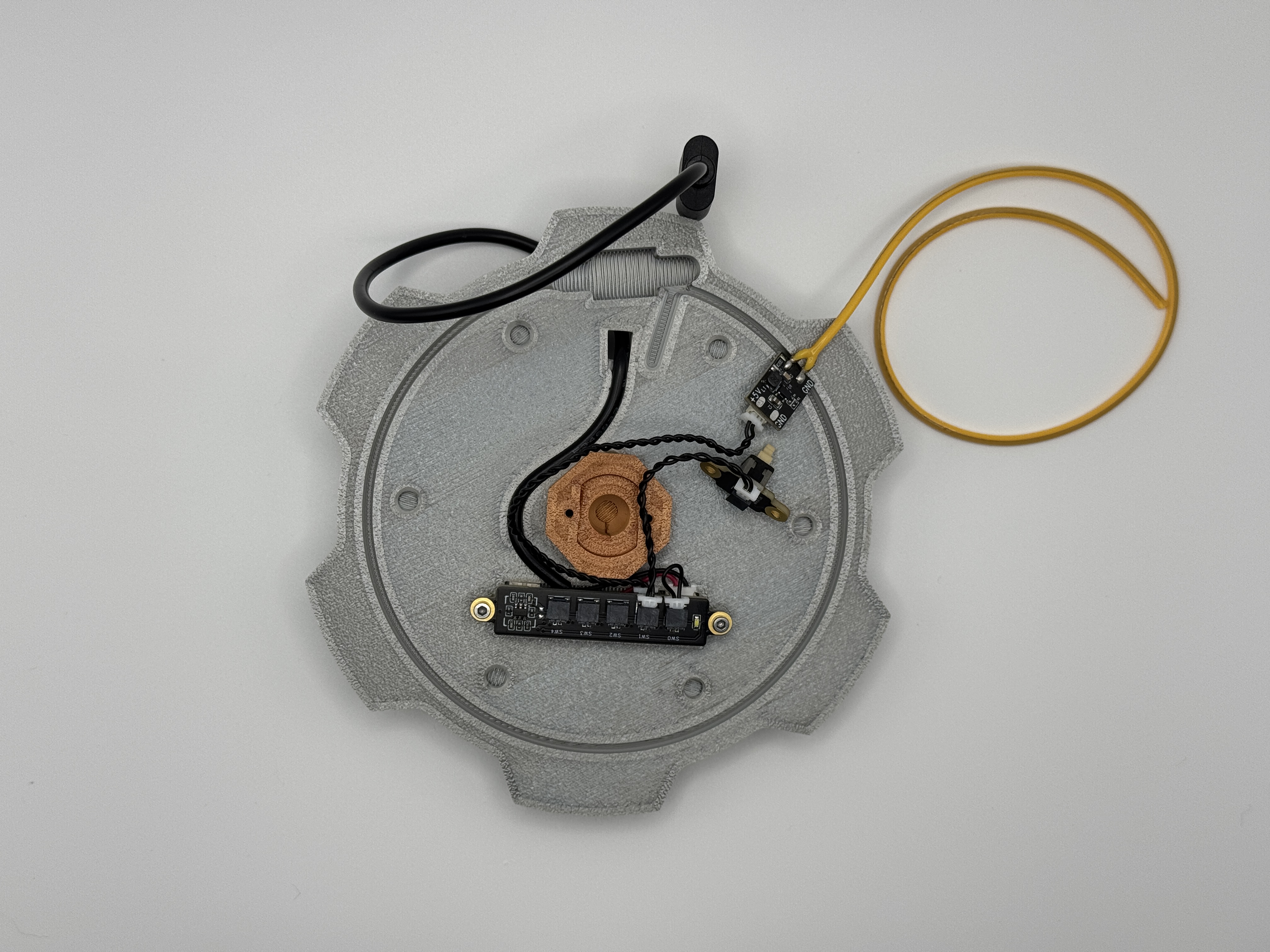
|
| 6. Use (2) more screws to secure the switch. |
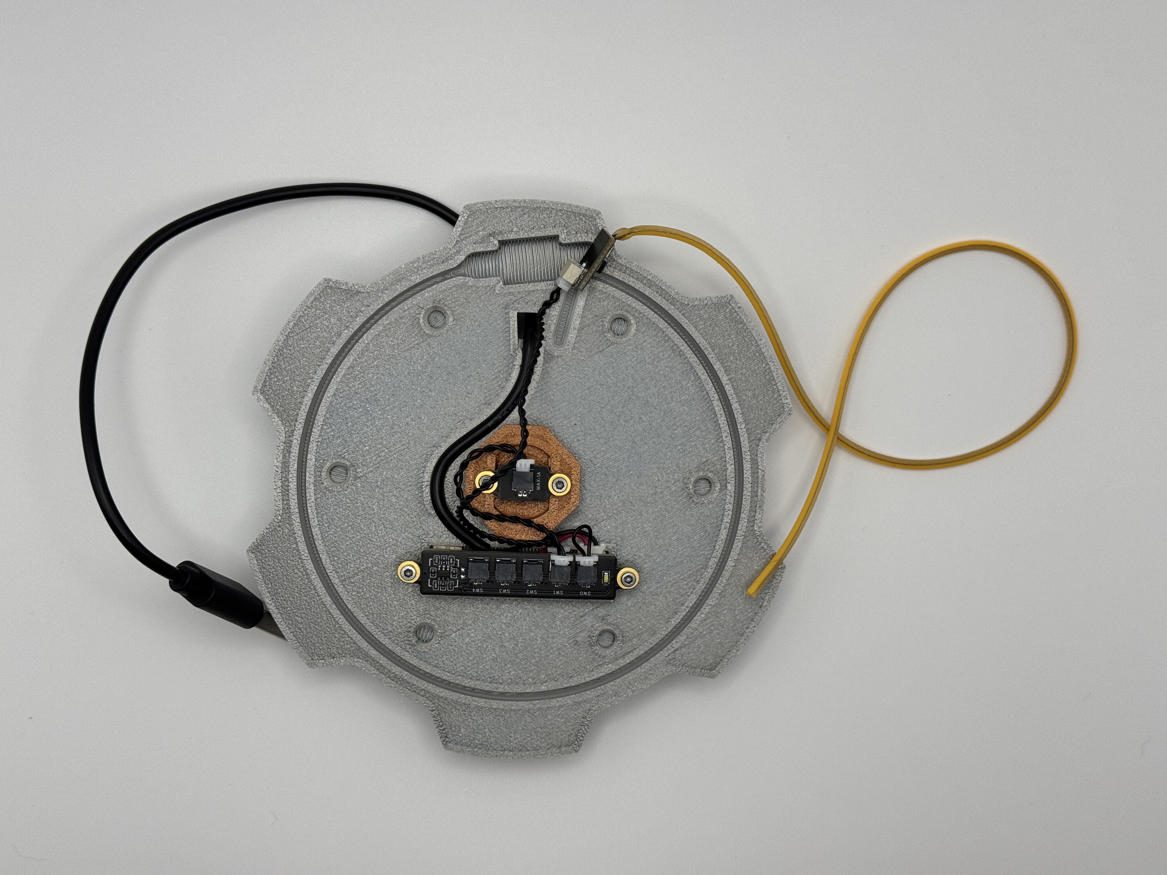 |
| 7. Place the COB light board in its rectangular cutout with the connector side up. Its ok if its at a bit of an angle - It will need to be entirely below the surface of the part. |
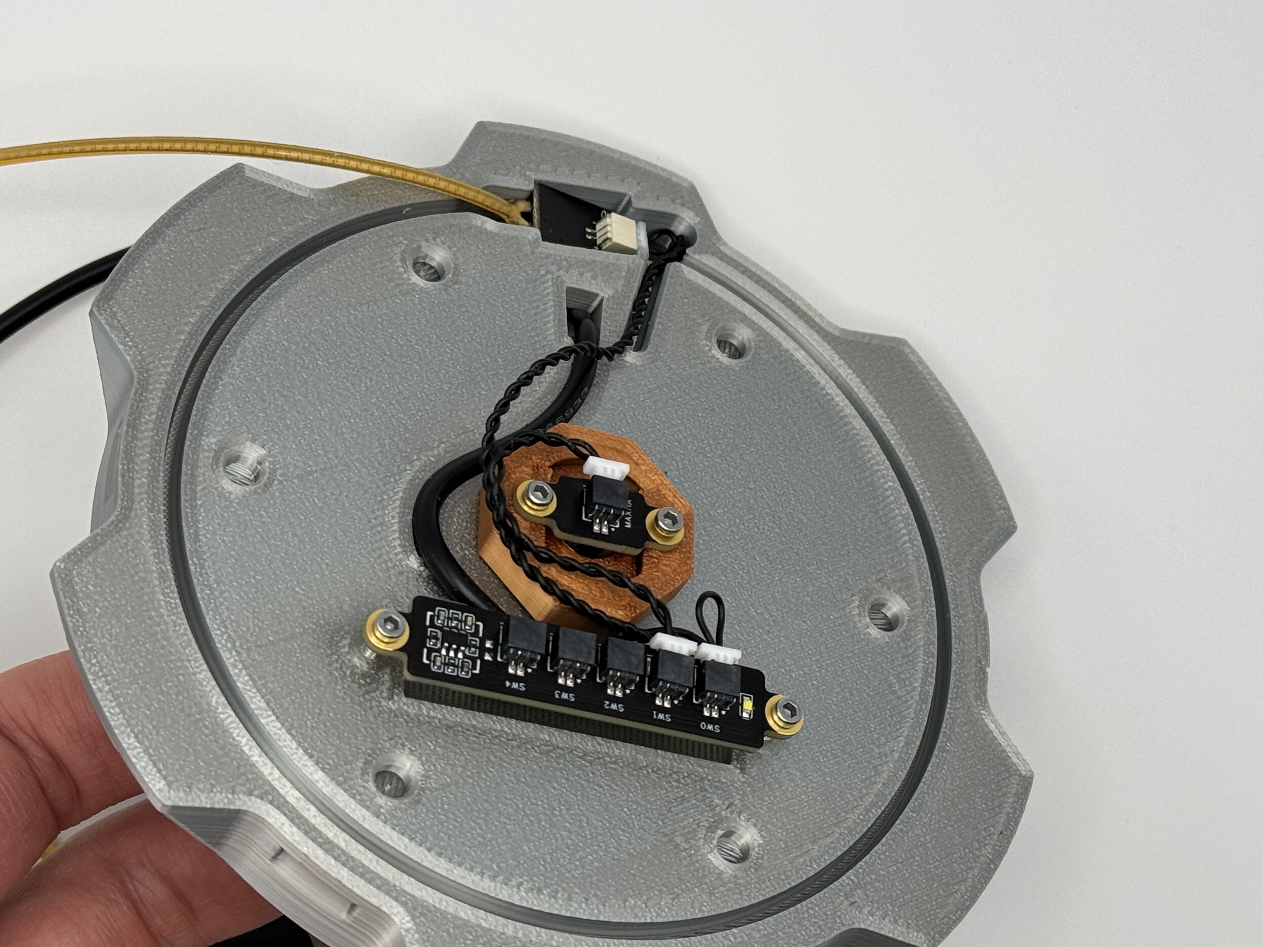 |
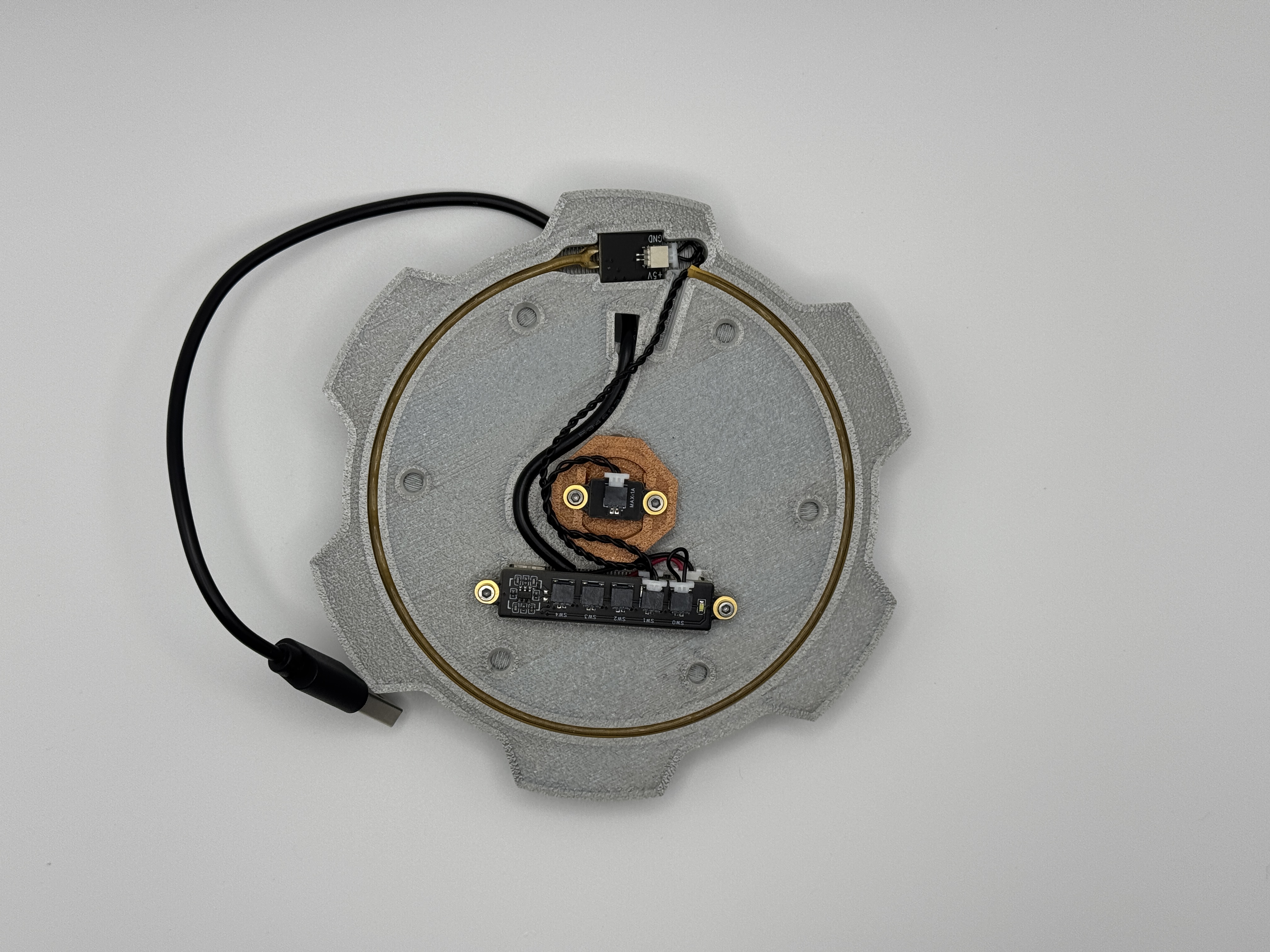
| 8. Push the light into the slot around the circle. I try to keep it from twisting so the brightness is uniform. |
 |
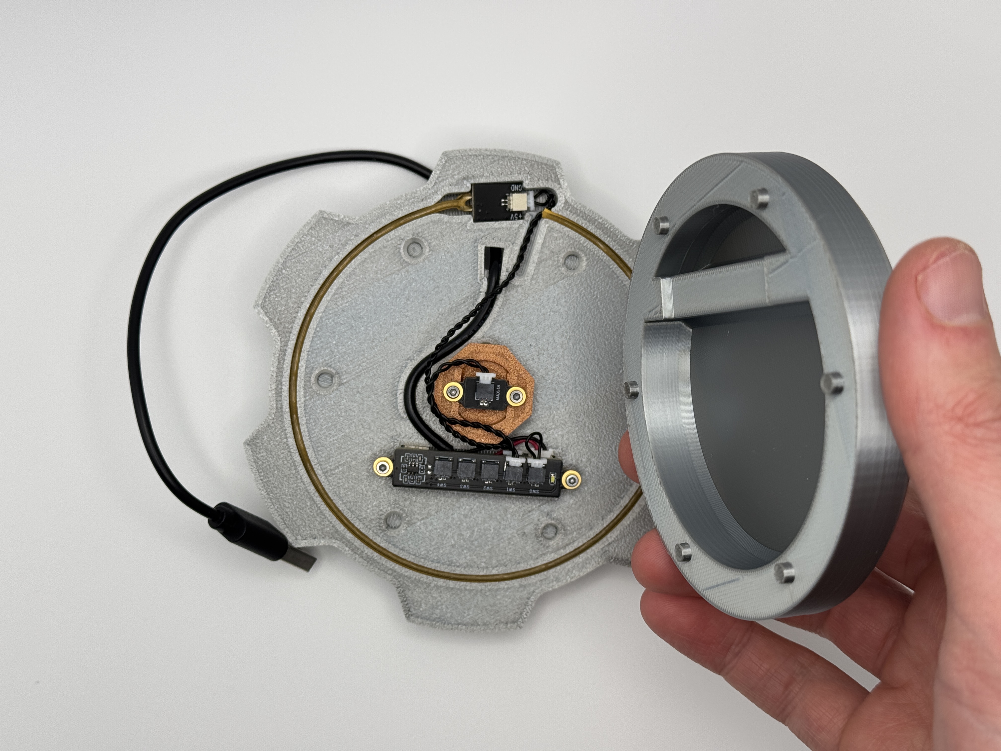
| 9. Put the inside cover on to protect the electronics. Note the orientation of the cover relative to the other parts. |
 |
| 10. Flip over and insert the accent piece on the end. Note that the accent pieces for the two ends are different sized - only one will fit here. If its not a tight fit you may want to install with a couple drops of glue. | 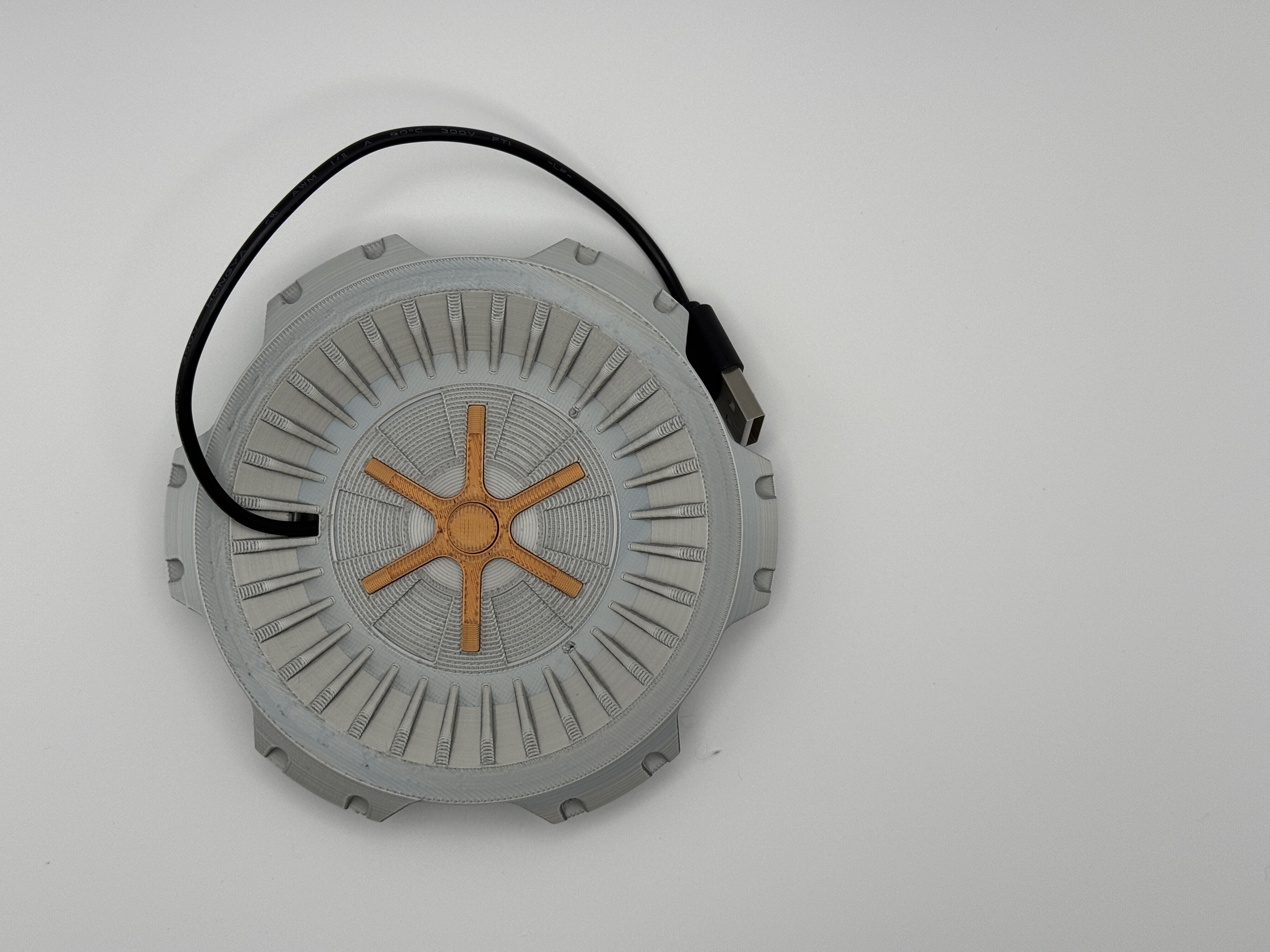
|
| 11. Test the electronics again before continuing assembly. |
Assembly with Acrylic Tube
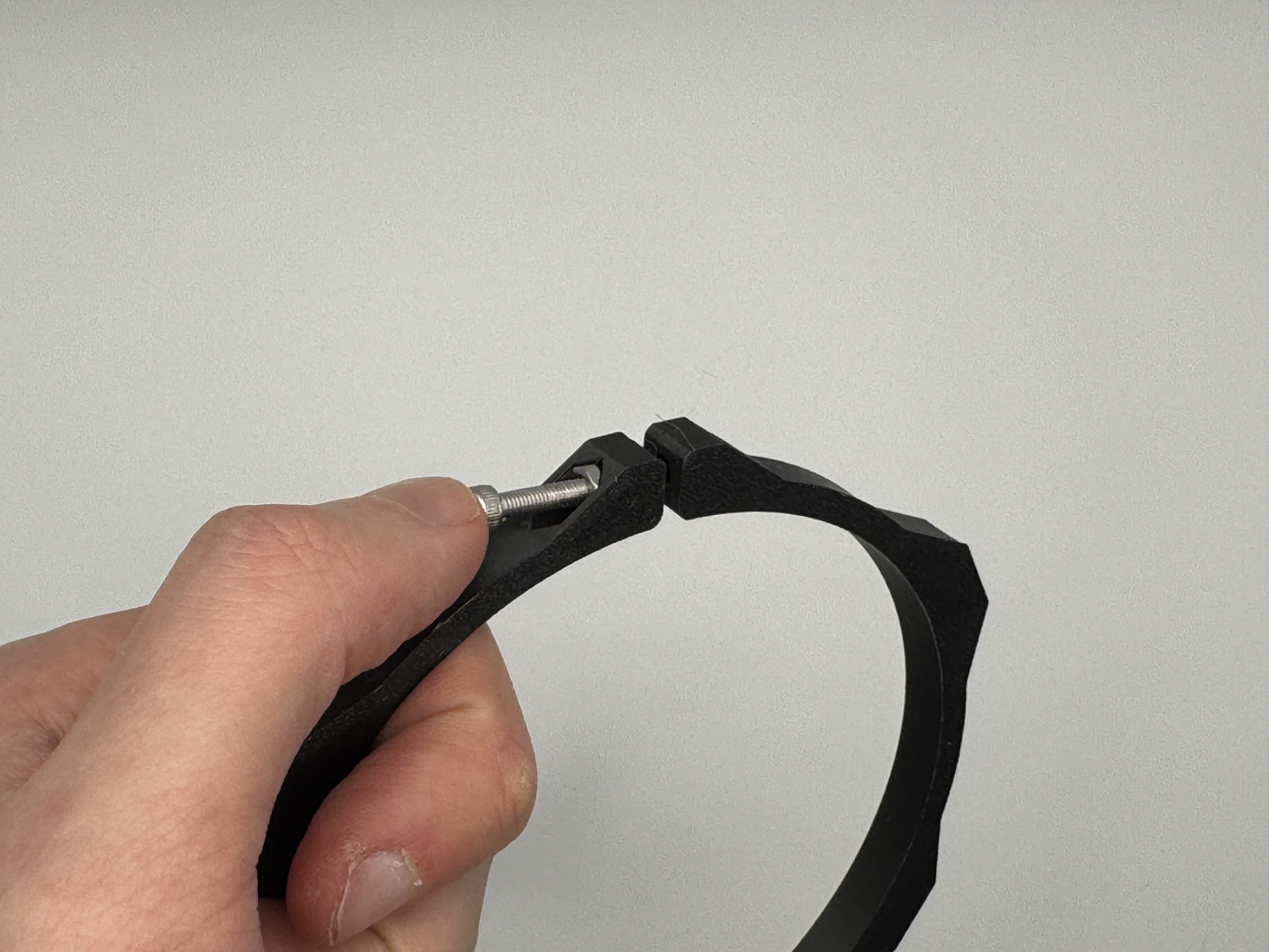
| 1. Install an M3 nut into each of the clamp rings. I recommend using the screw to push the nut in as shown. |
 |
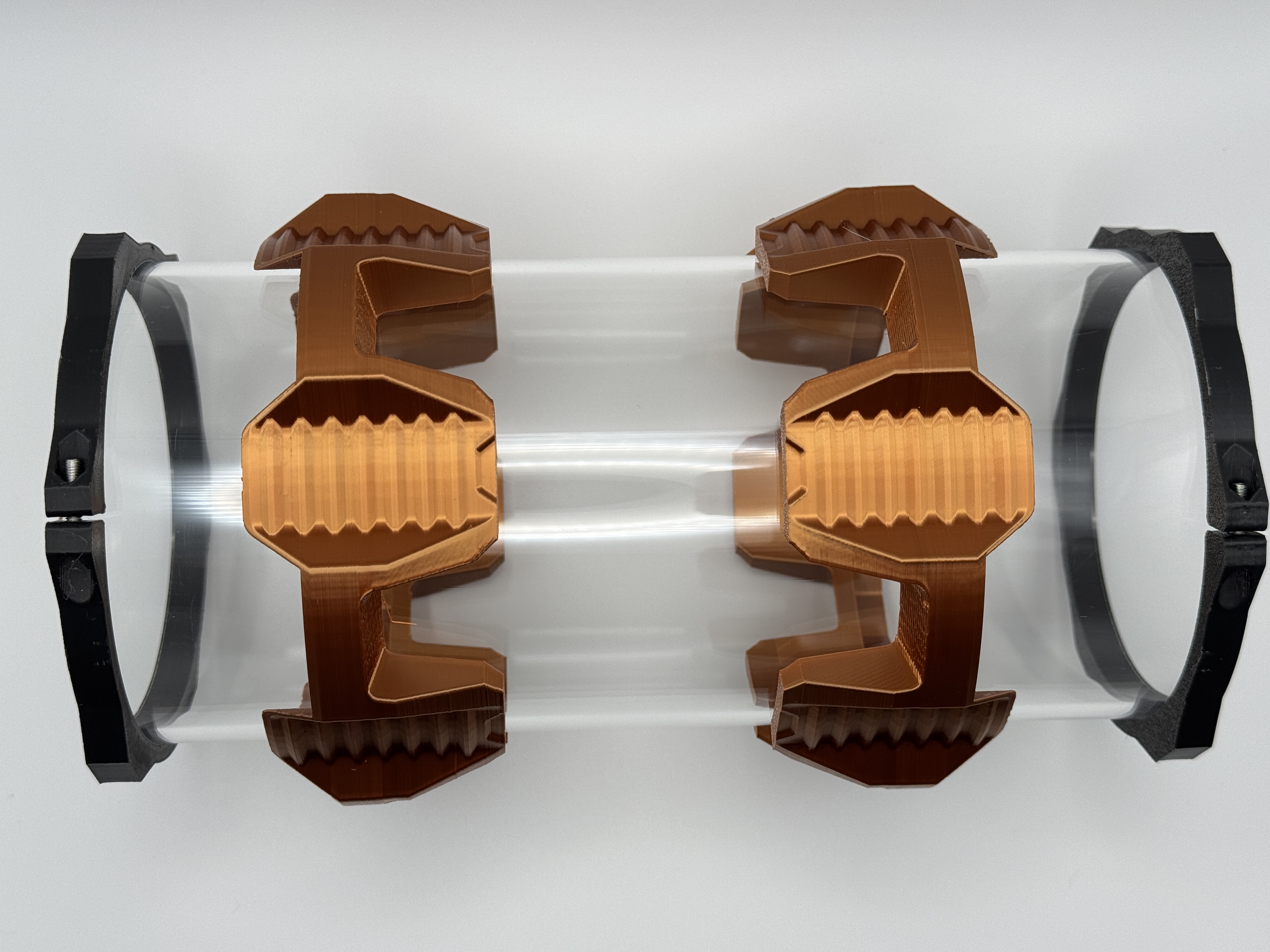
2. Slide the outer shell pieces onto the tube and then install a clamp ring on each end of the tube.
| 
|
3. Move the shell pieces to the ends. The following steps are difficult to dissemble, so proceed with caution if you haven't fully assembled the bottom. | 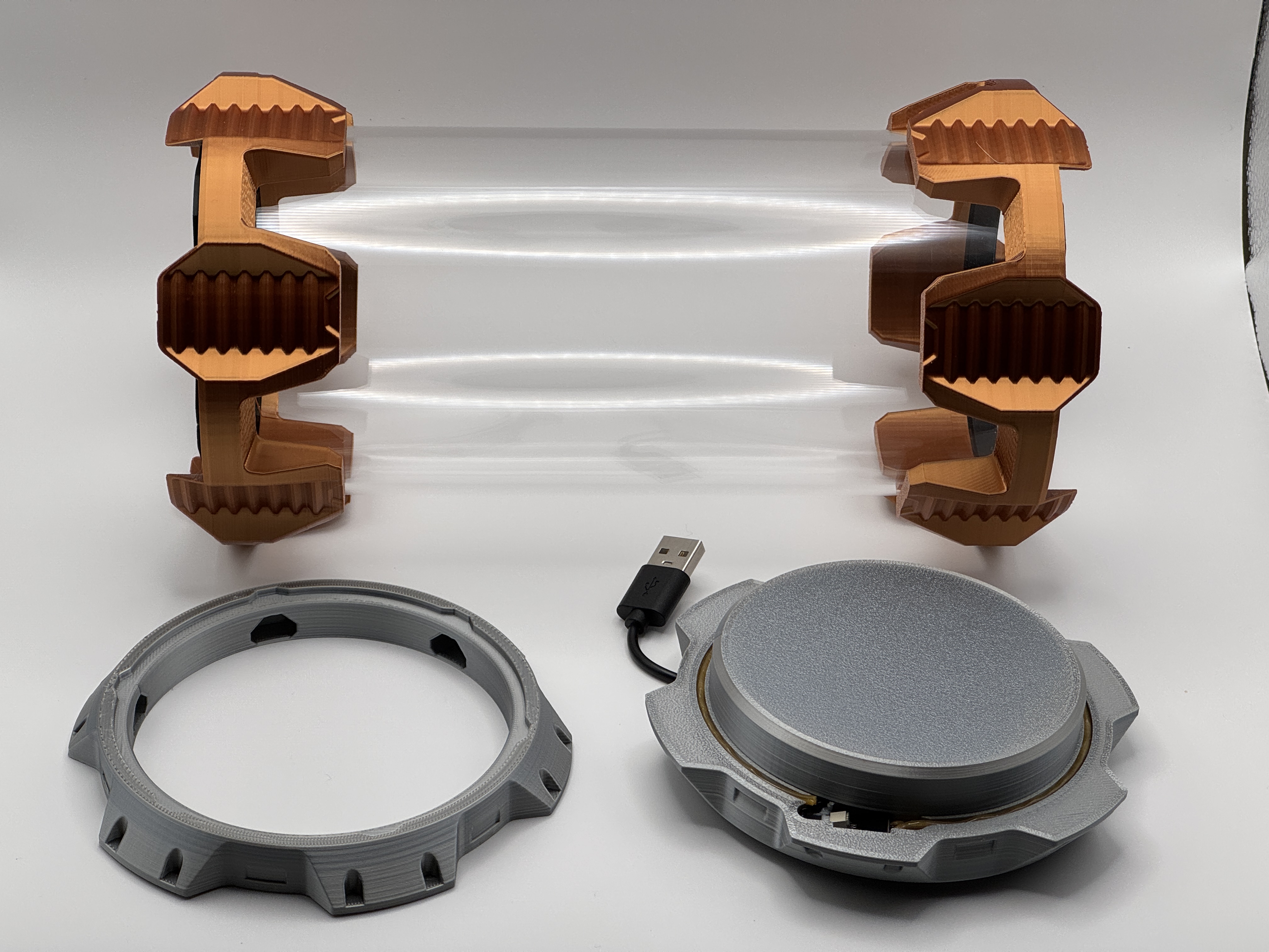
|
| 4. Line up the bottom assembly and snap into place. | 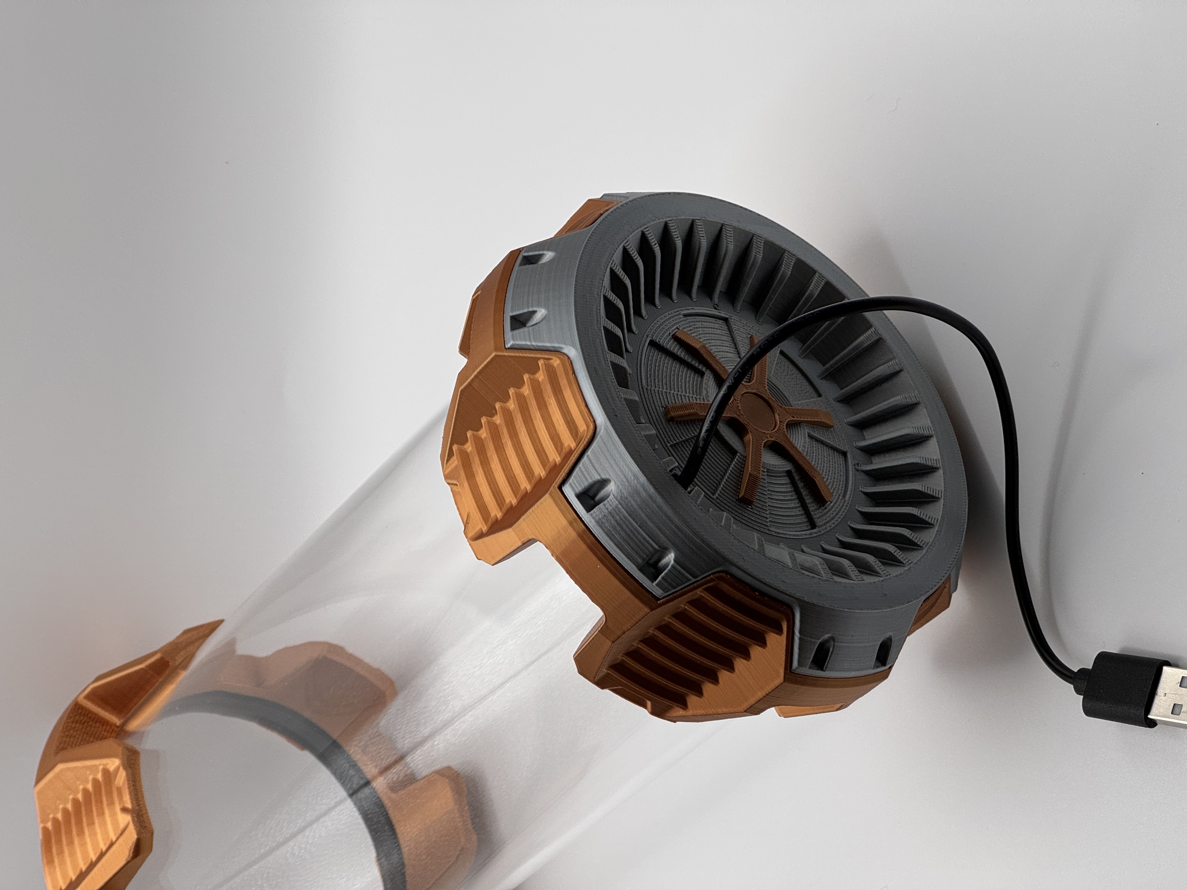
|
| 5. Line up the canister side of the lid and snap into place | 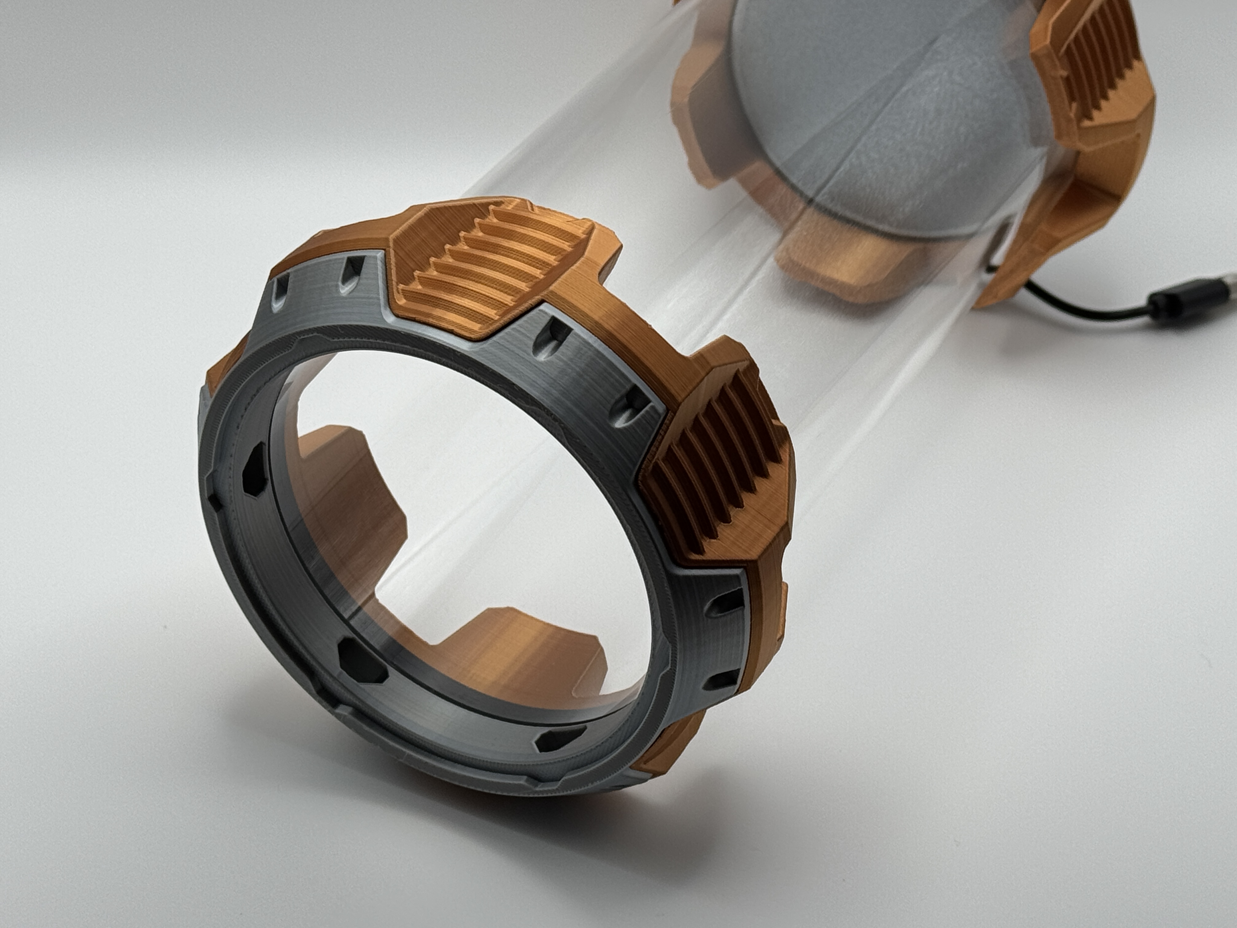
|
| 6. Install the lid/door assembly and make sure the latching works correctly. | 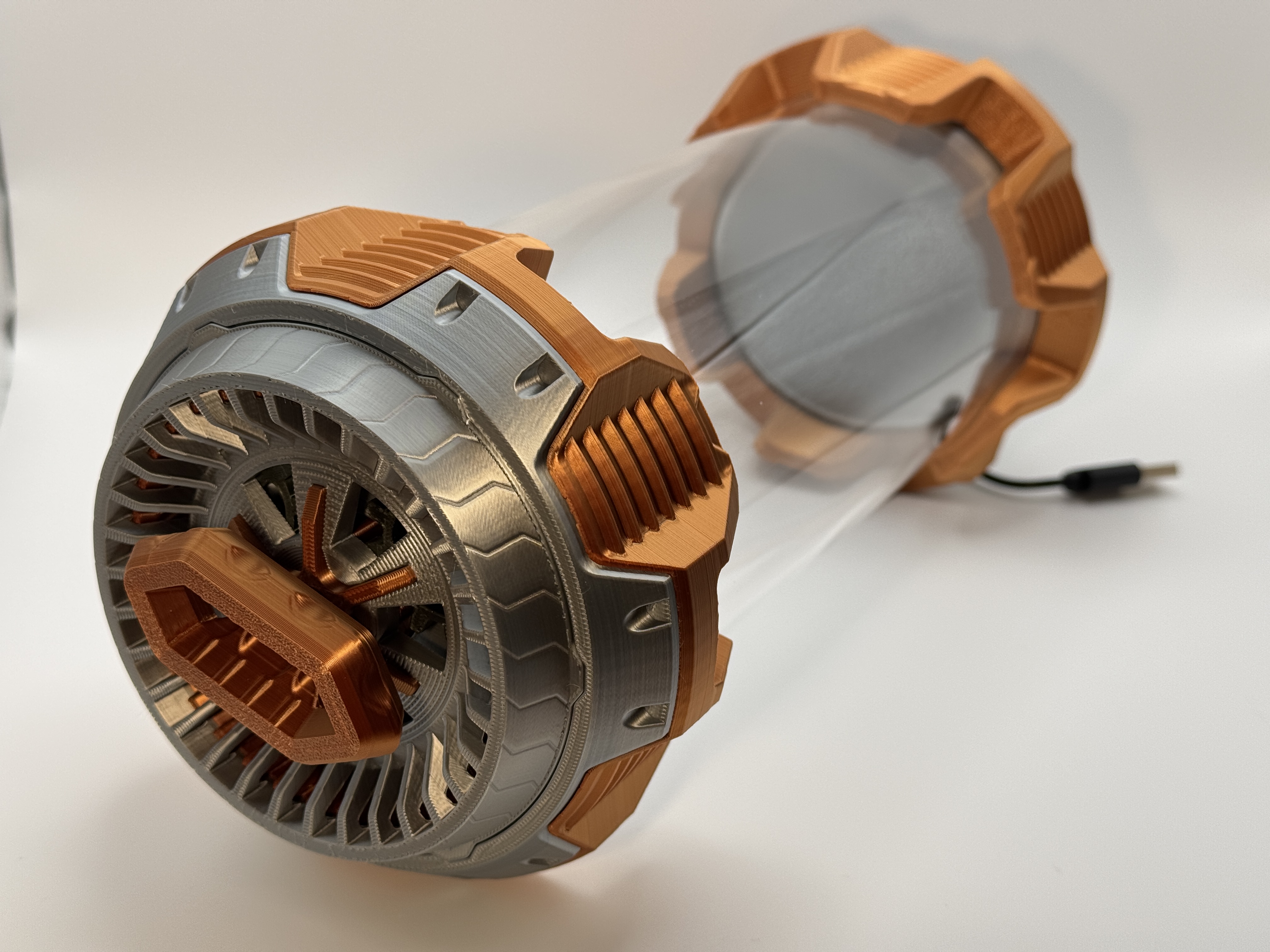
|
Stand Assembly
| 1. Position the feet, as shown, on the side with the pegs. | 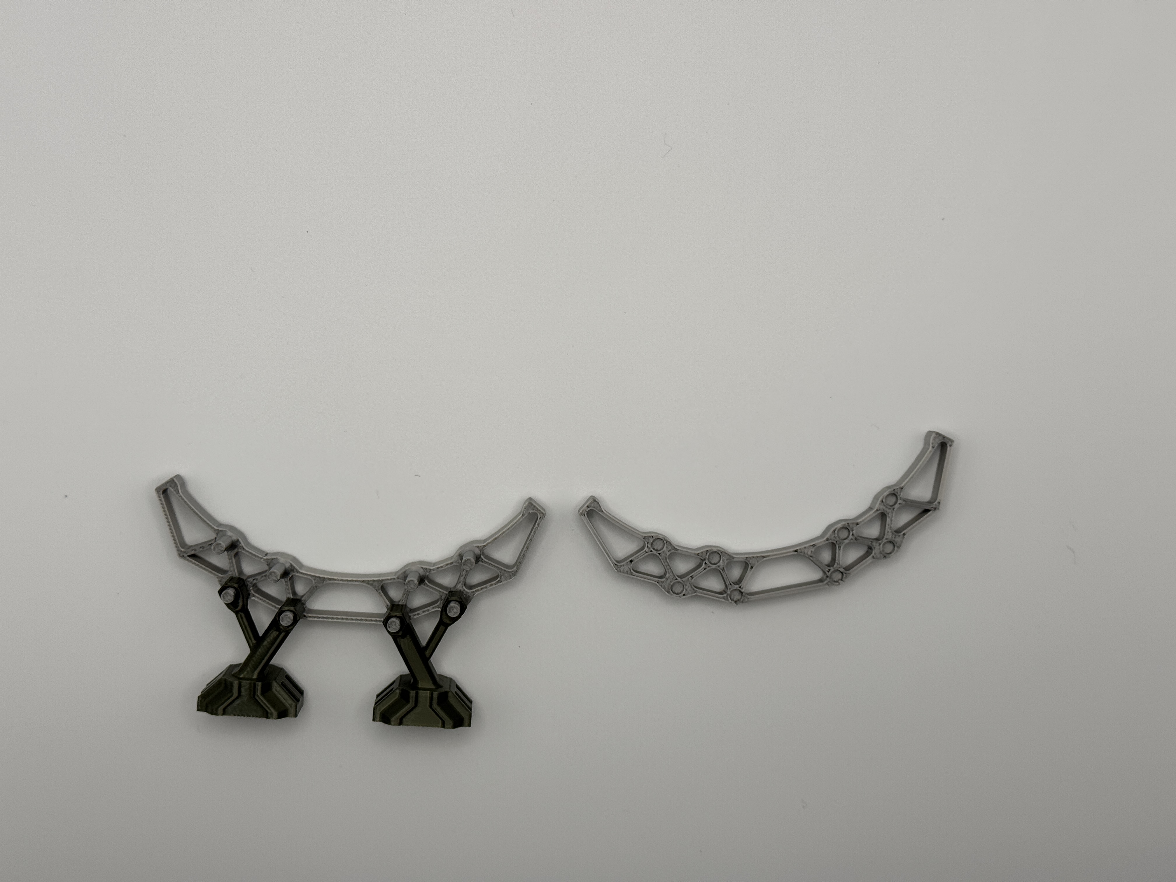
|
| 2. Snap the two sides together. If the fit is loose you may want to apply a bit of glue. |

Gostou deste modelo? Crie uma conta grátis para salvar seus favoritos e voltar a eles depois.
Criar conta